
3 Floater and Development concept Selection
3.1 General
This section deals with the development concept selection, which concerns (1) the type of the production floater and related equipment (e.g. oil & gas export system) and (2) the development nature of the reservoirs (i.e. subsea or dry trees or combination of).
The development concept selection is influenced by many factors, principally related to the reservoir properties and the location of the field. The main criteria which fix the type of floater and development are as follows:
Distance to existing infrastructures (hubs) or to shore
This parameter has a strong impact on the economy of the export system options. If a pipeline is generally the preferred solution, a too large distance (to shore or to adequate facilities) would lead to an offshore tanker loading option due to cost considerations. Refer also to Section Section 3.4, “Export System”.
The distance to existing infrastructures also impact the feasibility of a subsea tie-back development, which would consists in subsea wells located in deep waters and connected to shallower production facilities (refer to Section Section 3.11, “Subsea Tie-back”).
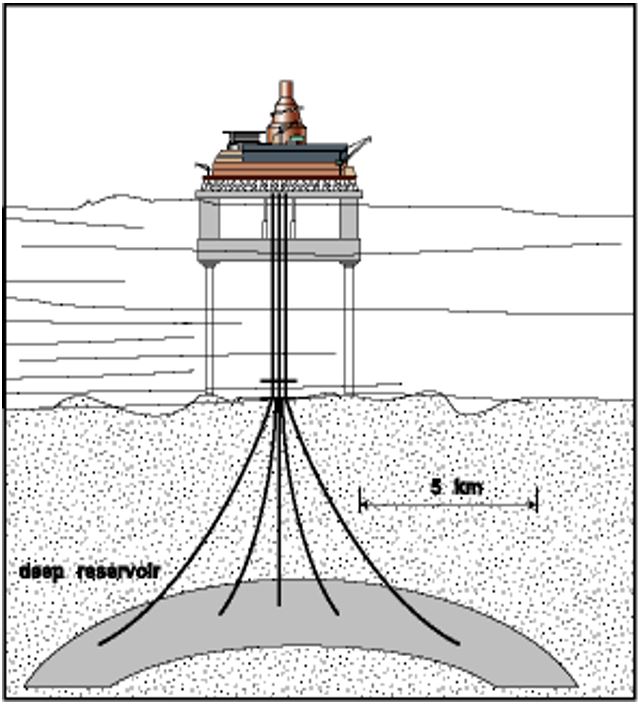
Number of drilling centres.
The types and distribution of reservoirs dictate the number of drill centres, which are required to adequately drain them. Despite the progress made in extended reach drilling, multiple drilling centres are often required, in particular when the reservoir is relatively shallow and has a large area or when the field features multiple reservoirs. This parameter (in combination with the well entry frequency, see below) mainly impacts the feasibility of a dry tree development, which requires a concentration of the wells for drilling operation from the same centre (refer to Section Section 3.2, “Dry versus Wet Trees”).
Well entry frequency.
A small number of drilling centres combined with a requirement for frequent drilling/workover would lead to a platform equipped with drilling equipment. In this case surfaced dry trees completion would be considered. Otherwise a dedicated drilling/workover vessel should be considered and the development would be subsea wet trees completion.
Other criteria can influence the field architecture and floater selection, such as:
Production capacity.
A small reservoir may suit a subsea tie-back configuration but a large one would be limited by the host platform capacity. A large field may require oil / gas export pipelines.
Reservoir fluid characteristics, e.g. pressure, temperature, chemistry (H2S, CO2 contents)
Environmental conditions.
The floater behaviour (under environmental loading) shall be considered especially in very harsh environment area. The typhoons or impact due to icebergs in ice prone areas may also be design criteria and would for example call for a disconnectable riser system (i.e. a FPSO based development featuring a disconnectable turret, refer to Section Section 3.3, “Disconnectable Riser System”).
Water depth, e.g. mooring and riser technologies
The following Section Section 3.2, “Dry versus Wet Trees” reviews the main criteria for selection of (surface) dry tree versus (subsea) wet tree development alternatives.
The impact of disconnectable risers and mooring systems on the development scenario is presented in Section Section 3.3, “Disconnectable Riser System”.
The options for exporting the produced effluent and gas are further review in Section Section 3.4, “Export System”.
The following Table 3.1, “Development Concept Alternative Summary” summarises the main development concepts based on the different alternatives for the above three main parameters. This table is not exhaustive, there is no universal solution and each project shall perform an adequate development concept selection to accommodate the field characteristics. The main development options per floater type are further described in the following sections (from Section Section 3.6, “TLP Based Development” to Section Section 3.10, “SSP based Development”). The long subsea tie-back option (i.e. no floater on the field) is developed in Section Section 3.11, “Subsea Tie-back”.
Table 3.1 - Development Concept Alternative Summary
Distance to shore or existing infrastructures | Number of drilling centres | Well entry frequency | Development Concept | ||
Floater | Subsea / Dry Trees | Offloading | |||
Short | Low | Low | Semi-sub | Subsea | Pipeline |
Subsea | Tankers | ||||
High | Dry Trees | Pipeline | |||
Compliant Tower | Dry Trees | Pipeline | |||
Spar, EDP | Dry Trees | Pipeline | |||
Semi-sub + Mini-TLP | Dry Trees | Pipeline | |||
Semi-sub | Subsea (adjacent) | Pipeline | |||
Dry Trees | Pipeline or Tankers | ||||
High | Low | Semi-sub | Subsea | Pipeline | |
Subsea | Tankers | ||||
High | Semi-sub + Mini-TLP | Dry Trees | Pipeline | ||
Dry Trees | Pipeline or Tankers | ||||
Distance to shore or existing infrastructures | Number of drilling centres | Well entry frequency | Development Concept | ||
Floater | Subsea | Offloading | |||
Long | Low | Low | Subsea | Tankers | |
Spar | Subsea | Tankers (OLS) | |||
Semi-sub | Subsea | Tankers (combined or not with a FSU) | |||
High | Dry Trees | Tankers (combined or not with a FSU) | |||
Spar | Dry Trees | Tankers (OLS) | |||
Compliant Tower | Dry Trees | Tankers (combined or not with a FSU) | |||
Dry Trees | Tankers | ||||
FPSO + Spar | Dry Trees | Tankers | |||
Semi-sub | Subsea | Tankers (combined or not with a FSU) | |||
High | Low | Subsea | Tankers | ||
Semi-sub | Subsea | Tankers (combined or not with a FSU) | |||
Spar | Subsea | Tankers (OLS) | |||
High | Dry Trees | Tankers | |||
FPSO + Spar | Dry Trees | Tankers | |||
Notes:
The offloading to tankers (when not specified) can be either direct tandem loading or through an Offshore Loading System (OLS). See the following Section Section 3.4, “Export System” for further details.
The developments based on dry trees can also include additional subsea trees, e.g. subsea water injection trees
The impact of these parameters on the development concept is further developed in the different following sections.
3.2 Dry versus Wet Trees
The development concept selection is based on the criteria summarised in Section Section 3.1, “General”.
The selection of subsea development versus dry trees mainly relies on:
The reservoir geometry and distribution (deep or shallow reservoirs) which determines the number of required drill centres for efficient production drainage.
The expected well entry operations, which (in case of high frequency) could beneficiate to a floater equipped with workover facilities.
3.2.1 Dry Trees
A relatively high number of expected workover operations combined with a reservoir requiring a single drilling centre is typically leading to a dry tree development scenario. It could possibly be combined with some subsea wells tied-back to the floater if some wells are too far to be reached from a single drill centre. Dry trees floaters allow for a direct well access for remedial drilling operations; hence fore a cost reduction over a subsea development in terms of OPEX.
Dry trees can be fitted on floaters which feature low motions, in particular when considering heave. The relative motions between the floater and the wells (which are directly connected to tensioned rigid vertical risers, see Figure 3.2, “Matterhorn Project (W&T Energy) – Production Riser configuration featuring Dry Trees” to Figure 3.4, “Riser Tensioners on the Matterhorn TLP - Cellar Deck Level (refer to Figure 3.2, “Matterhorn Project (W&T Energy) – Production Riser configuration featuring Dry Trees”)”) are generally absorbed by flexible jumpers (refer to ).
The TLP, Spar and EDP floaters are well suited for a use in conjunction with surface completed wells (refer to ). Platforms such as compliant towers can also be used for dry tree support.
The use of surface trees for ultra-deepwater development is limited by the requirement for (1) a tensioning system for the vertical risers (i.e. limitation in term of riser weight/tension and hence of riser length) and (2) a one-to-one number of riser per well (limits in terms of vertical loads on the platform, i.e. a combination of riser number and water depth).
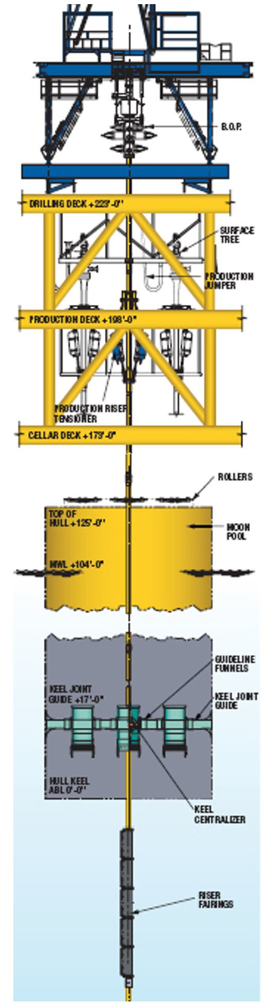
Figure 3.3 - Surface Trees on the Matterhorn TLP - Production Deck Level (refer to Figure 3.2, “Matterhorn Project (W&T Energy) – Production Riser configuration featuring Dry Trees”)
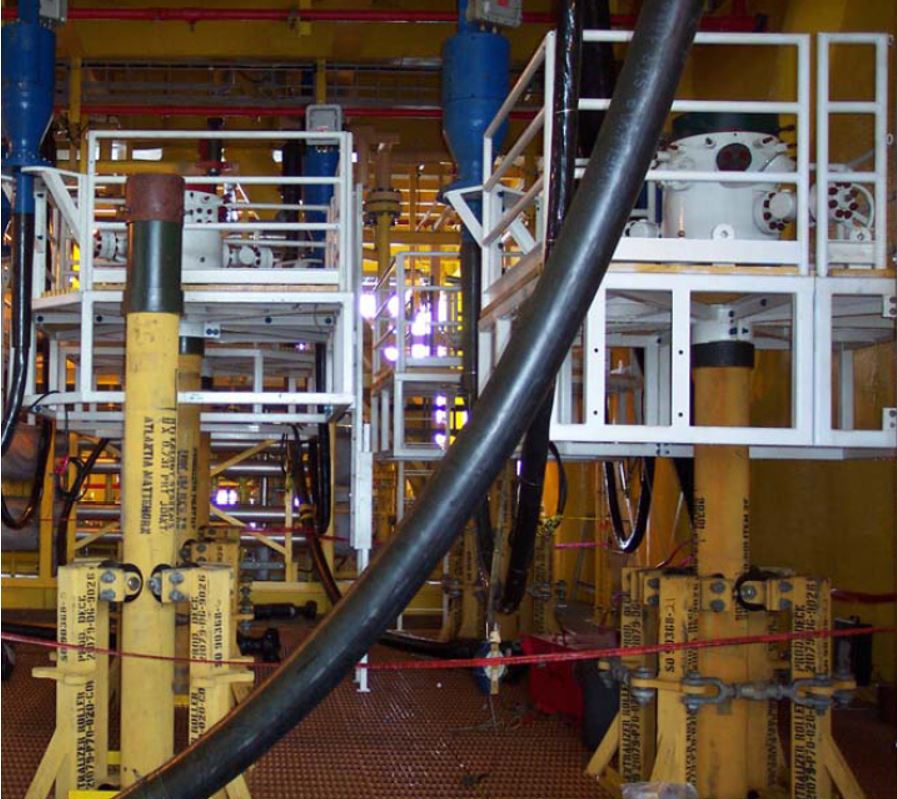
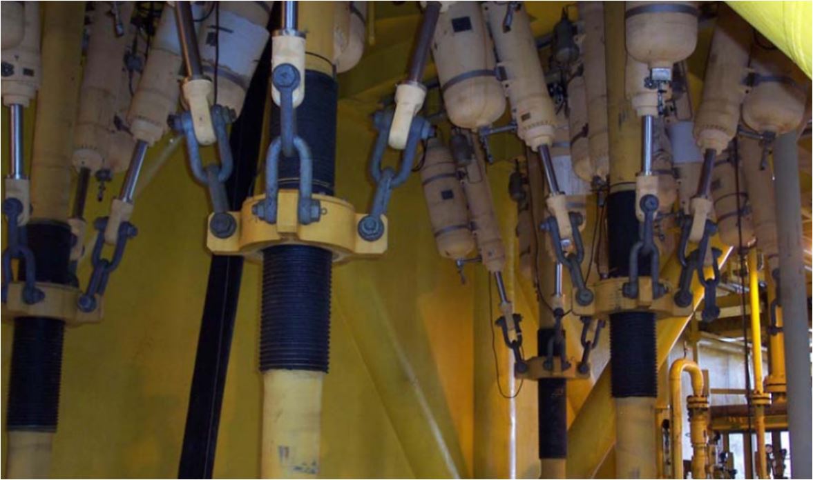
Figure 3.4 - Riser Tensioners on the Matterhorn TLP - Cellar Deck Level (refer to Figure 3.2, “Matterhorn Project (W&T Energy) – Production Riser configuration featuring Dry Trees”)
For some specific field development, both dry trees and wet trees can be used, as it was the case for Moho Nord project which included the development of two distinct reservoirs:
Wet trees connected to a PU were selected for the Miocene carbonates,
Dry trees on a TLP (Tension Leg Platform) were selected for the Albian carbonates whose specificities (very low matrix permeability and oil prone to asphaltene precipitation) required frequent interventions (well stimulation via acid injection, anti-depositing treatments) by operators.
3.2.2 Wet Trees
The wet trees (i.e. subsea development) allow for more flexibility with regard to the well and drilling centres locations from the floater. They are widely used in deep waters as they allow for wide spread field layout and for optimised reservoir drainage. A subsea development also allows reducing the overall riser count (and hence the payload on the floater and finally the hull size) by using manifold and commingle flowline system on the seabed (see Chapter 4, Well Architecture ).
All types of platforms can be considered when using subsea trees for the development (refer to ).
3.3 Disconnectable Riser System
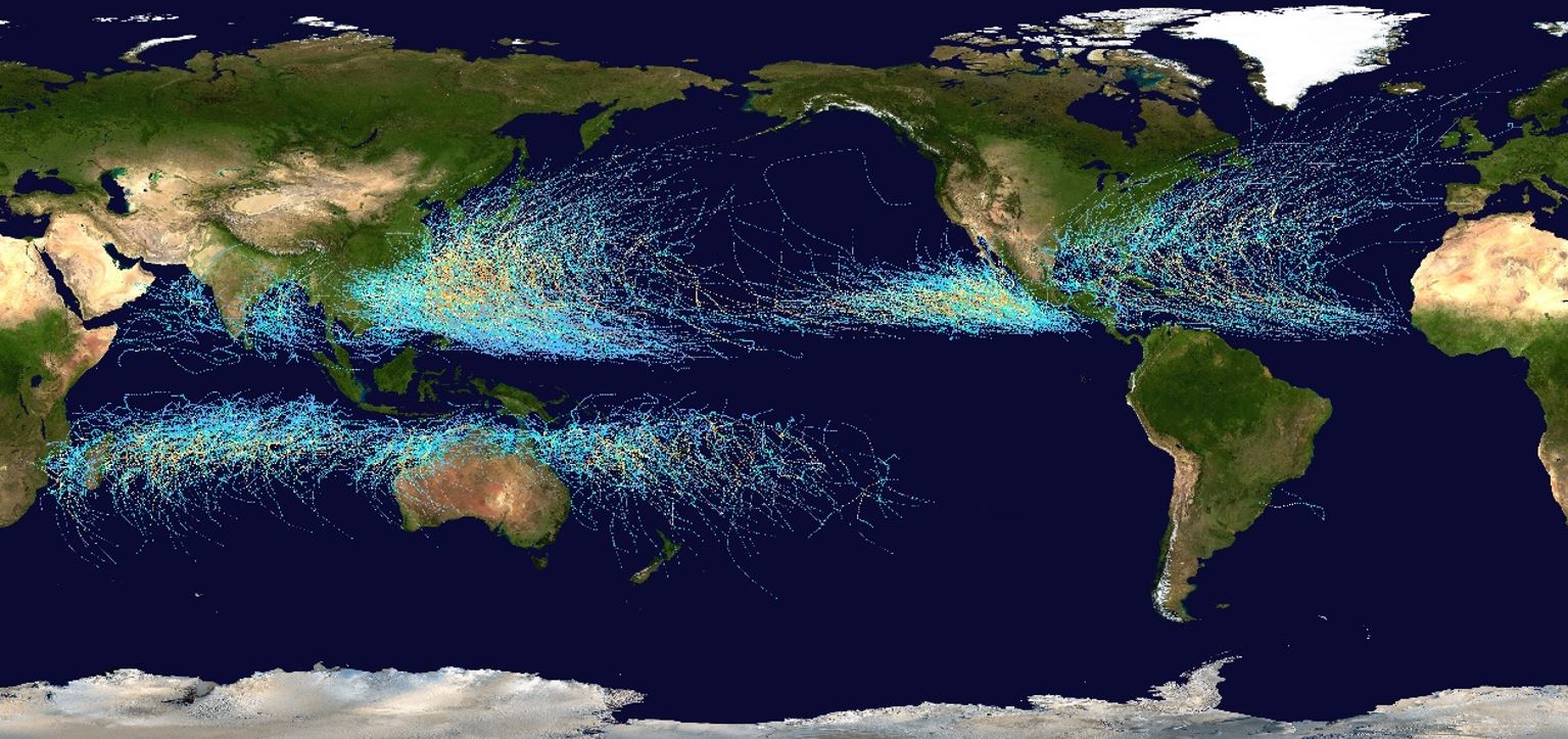
Hurricanes and typhoons are a major threat when considering operations in regions such as the Gulf of Mexico or the Far East. In 2005 many GOM installations suffered extensive damages due to the hurricanes Rita and Katrina.
The shows that typhoons and hurricanes occur in areas close to the equator, in the Pacific Ocean (Asia, Australia) and in GOM. An offshore field development in regions exposed to such seasonal events shall be based on "hurricane-proofed" systems.
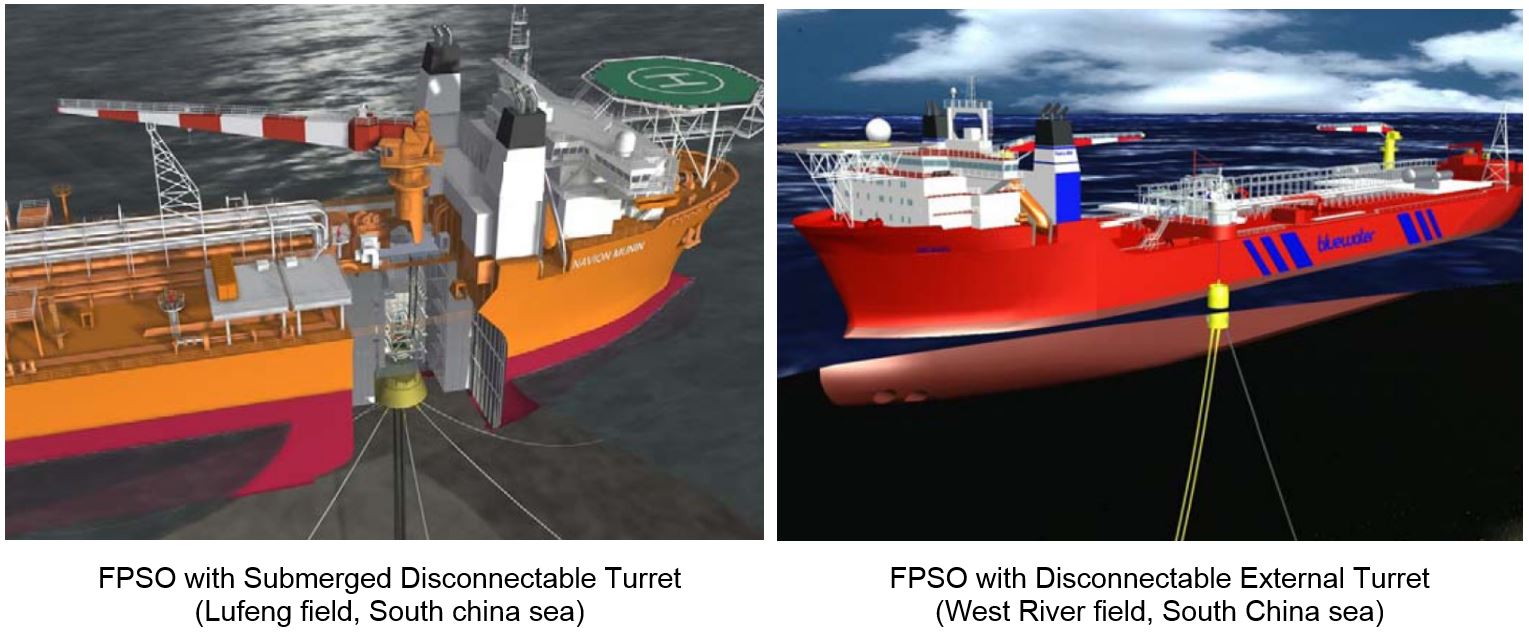
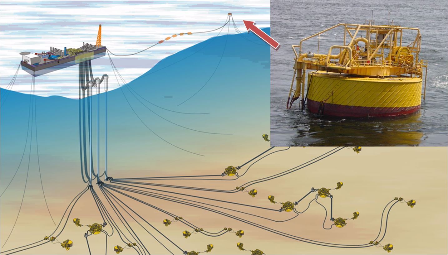
Around thirty disconnectable FPSOs are used worldwide, mainly in hurricane prone regions (i.e. North Australia and South China) and some in the iceberg prone regions (e.g. Eastern Canada). Such systems are now strongly considered to allow the use of FPSOs in the GOM, e.g. Petrobras Cascade / Chinook development. They typically comprise a turret buoy with spread mooring system, a clump weight system and a winching arrangement for planned disconnecting and connecting operations. A large buoy is required to support the risers, umbilicals, mooring legs and the clump weight system.
The system is usually connected to the vessel either at the bow to allow weathervaning or at the side (see ). Of the thirty existing disconnectable FPSOs, eighteen feature an internal turret, while the others have different types of design (external turrets, riser turret mooring, single anchor leg yoke, jacket soft yoke, dynamic positioning, buoy turret mooring and one spread moored).
The use of such system in deep waters would tend to lead to internal turret based systems due to the riser system vertical loads.
Prior to the onset of extreme weather conditions, the buoy is released from the FPSO which then sail-away from the treated area. Once disconnected, the buoy sinks to a controlled depth in the water column below the wave action zone, from where it may be recovered and reconnected. Refer to for further technical details.
A disconnectable riser system allows removing the personnel and asset from the path of hurricanes (or icebergs) by sailing away. It reduces the safety and environmental risks, in particular:
Mooring system failure
Structural damages, e.g. due to hurricane wave / wind or iceberg impact
Reduced requirement for personnel evacuation means (e.g. helicopter)
Such a riser system could also minimise the risks related to the FPSO / installation schedule by allowing a pre-installation of the riser system (pending on the design).
The main challenges related to disconnectable riser systems in deepwater include:
The behaviour of the riser system, in particular in disconnected position. Clashing between the risers and / or mooring lines are critical design criterion particularly when considering the low (disconnected) position of the buoy. The system shall be sufficiently robust to survive the dynamic loads and offsets experienced during the different phases (disconnection, reconnection and submerged states).
The vertical loads induced by the risers, umbilicals and mooring lines.
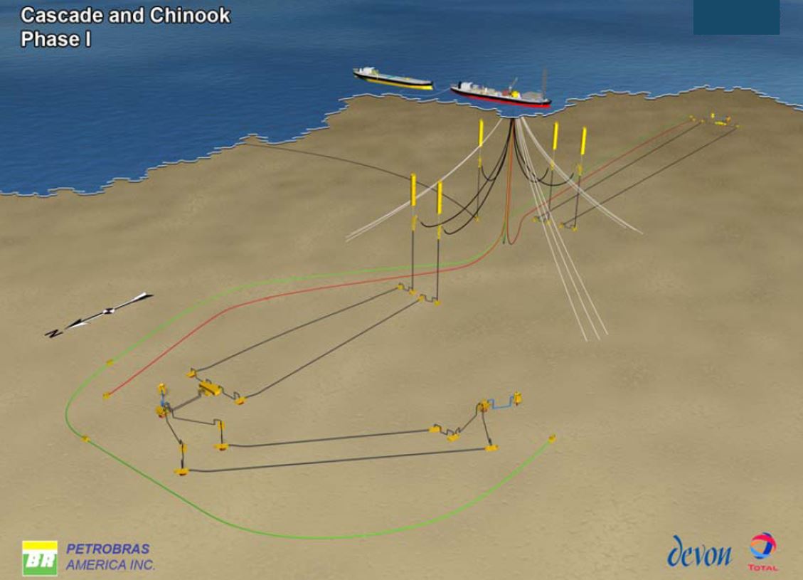
For these reasons, a disconnectable riser system in deep water is generally considered in combination with hybrid risers, i.e. including a submerged buoyancy system (refer to ). Subsea arch/buoyancy allows for a reduction of the weight to be supported by the system buoy when disconnected and helps to control the minimum clearance between the different lines as acting as "guidance" device located at shallow water depth.
The figures below depict (1) the Cascade / Chinook development, which would be based on Free Standing Hybrid Risers, and the SEAL Engineering's HySRTM combined with a disconnectable system.
It is worth noting that recent projects have chosen a different approach to mitigate the risks of hurricanes or typhons. The projects Ichthys and Prelude located North West of Australian coast and in a typhoon area have both designed their floating structures (one FPSO and one semi-submersible for Ichthys and one FLNG unit for Prelude) to withstand the harsh environment during a typhonn.

![[Tip]](tip.png) | Tip Click these links below for access to 3D resources: |
3.4 Export System
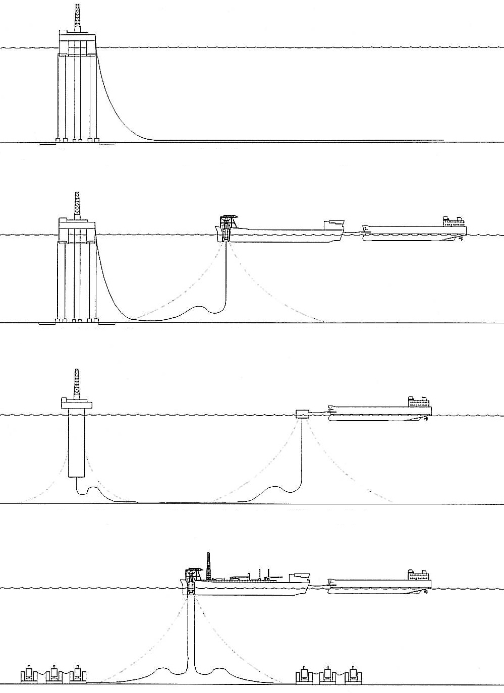
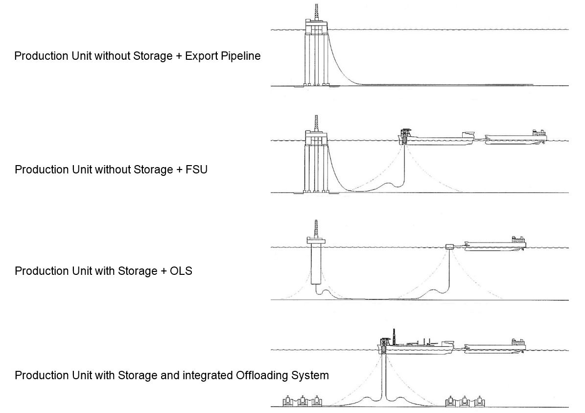
The export of the produced effluent is performed by means of either dedicated pipelines or tankers of opportunity. The selection of the export system is related to the 'distance to shore or existing infrastructures' (see Section Section 3.1, “General”).
Generally, an in-field temporary storage of the effluent is required to avoid production shutdown due to unavailability of the export system (e.g. weather conditions forbidding offloading to tanker). The in-field storage can be either performed in the production unit itself (e.g. FPSO, Spar) or stand-alone (FSU).
If export is performed by offshore tanker loading, the system can be either integral to the production facility (e.g. FPSO offloading in tandem configuration) or stand-alone Offshore Loading System, OLS). An OLS is generally preferred for safety reasons as it allows for a minimum distance between the zone of offloading and the production facility, e.g. 1 nautical mile. It also allows full 360° weathervaning of the tanker for offloading operations in a wide range of environmental conditions.
The OLS generally consist in an offloading buoy located at around 2km from the floater and anchored by a spread mooring system. It provides an anchoring point to the tankers during the loading operations. It is connected to the floater by two (to three) lines in a simple catenary or camel shape configuration.
The floaters featuring the highest storage capacity are the FPSO (or SSP), the spar and the semi-submersible (in decreasing order). The TLPs are very sensitive to weight variations, which directly impact the tension in their tendons, and are not prone to massive effluent storage. The compliant tower concept does not feature tanks capable of storing the produced fluids.
The main export system options are depicted in the following :
| Tip Click these links below for access to 3D resources: |
3.5 Fluid Transfer Lines
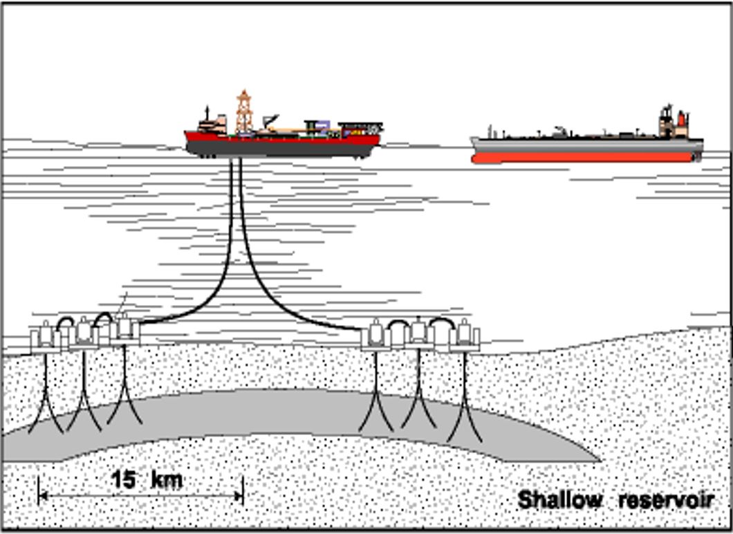
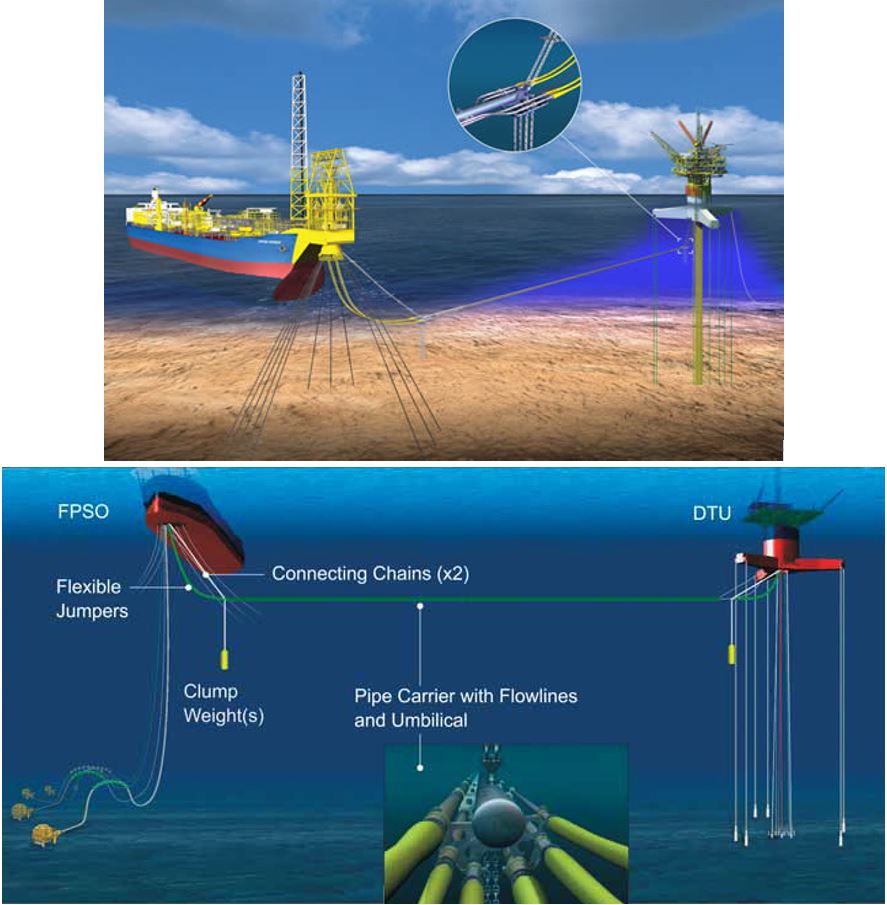
In some cases, a field development can involve two floaters, i.e. generally a surface wellhead platform (mini-TLP, Spar, EDP) and another floater for the processing (storage) of the effluent.
The two platforms are then linked by a Fluid Transfer Lines (FTL), which transfer the raw fluids from the surface wellhead platform to the process floater. Due to the importance of the water depth compared to the distance between the two platforms, the FTL do not generally go back to the seabed to rise again to the other floater. Such long route passing down to the seabed would cause flow assurance issues, with the possibility of hydrates and wax appearance due to the transfer of non-treated fluids.
A possibility of mid-water FTL to benefit from warmer sea temperature and to decrease the length of the transfer line is to hang the different lines in catenary configuration between the two floaters. This configuration has already been applied on the ExxonMobil Kizomba A and B developments (see Section Section 3.6.5, “Kizomba A and B developments”).
Another solution consists in using a neutrally buoyant bundle of lines located at a near surface depth to transfer the fluids. This allows minimising both (1) the transfer line length and (2) the thermal exchange as only the 'warm' surface water is encountered. This quite innovative configuration has been selected for the Murphy Oil Corp.'s Kikeh field (see Section Section 3.7.3, “Kikeh Field”) with a patented system called Gravity Actuated Pipe (GAP).
The GAP consists of a bundle of steel pipes supported and tensioned by chains and weights attached to the floaters. The lines are connected to the platforms by flexible jumpers. The GAP's neutrally buoyant bundle allows minimising the load supported by the floaters and hence allows some flexibility in the distance between the platforms.
3.6 TLP Based Development
3.6.1 TLP Main Features
TLPs have seen applications in water depths up to 1581m in the GOM and WOA. The water depth is limited for this type of floater by the tendon mooring, as the tension forces rapidly increases (with their weight) in very deep waters. This results in a large hull buoyancy requirement, which then requires reinforced tendons. The TLP design spiral (refer to ) becomes more acute for large topsides and in severe environmental conditions.
The total number of risers in ultra deep waters is constrained for similar reasons related to their weight.
The TLP can support dry surface trees, which facilitate the drilling/maintenance operations on the wells and hence can increase the production availability. The TLP concept supporting dry trees with top tensioned risers is a proven technology in the North Sea, in deepwater GOM and in deepwater WOA.
3.6.2 Mini-TLPs
Several Mini-TLP have been installed in the 2000’s (e.g. Matterhorn, Typhoon, Neptune, refer to ). The mini-TLPs are designed to support just the well system with minimum facilities. It offers an alternative to subsea templates with the intervention advantages of surface completed wells. The mini-TLP is very well suited for low well counts and small topsides applications due to its very light hull (see Matterhorn application, Section Section 3.6.4, “Matterhorn Project”).
Another application of the mini-TLP is an utilisation as 'pure' surface wellhead support, in combination with another floater for effluent process. Such configuration has already been used, e.g. on Kizomba A and Kizomba B (see Section Section 3.6.5, “Kizomba A and B developments”).
3.6.3 Ursa Project
This section briefly describes the Ursa project as an illustration of a field development based on a conventional TLP.
The Ursa unit is located approximately 210km south-east of New Orleans in the Mississippi Canyon (GOM) at a water depth of around 1200m. Field production began in 1999.
The TLP is of conventional type, featuring four circular steel columns, which are 26m in diameter and 54m high, connected to a ring pontoon 11.5m wide and 2.8m high, with a rectangular cross section. It weighs approximately 28,600t.
The deck is comprised of six modules, namely the wellbay, quarters, power, drilling and two process modules. These deck modules are arranged in an open-truss frame design, 90mx90mx15m-high, with a total steel weight of approximately 12,500t. The total topside weight is approximately 22,400t, including all equipment and the drilling rig. It incorporates complete separation, dehydration and treatment facilities, designed to process 150,000bbl of oil and condensate per day, plus 400MMcf of gas and 50,000bbl of produced water per day.
The TLP is held on-station by 16 tendons, four per corner. The lower end of the tendons is attached to receptacles secured in the foundation system consisting of 16 piles.
There are 24 well slots and the well layout on the seafloor was arranged in a rectangular pattern, approximately 30mx18m. Three of the planned development wells from the 24-slot TLP were pre-drilled. The TLP supports a single modified API platform-type drilling rig (leased) equipped with a surface BOP and a high-pressure drilling riser.
Production from the platform is transported approximately 75km via an 18in-diameter oil pipeline and a 20in-diameter natural gas pipeline, to the West Delta 143 platform. Steel catenary risers are used to connect the pipelines.
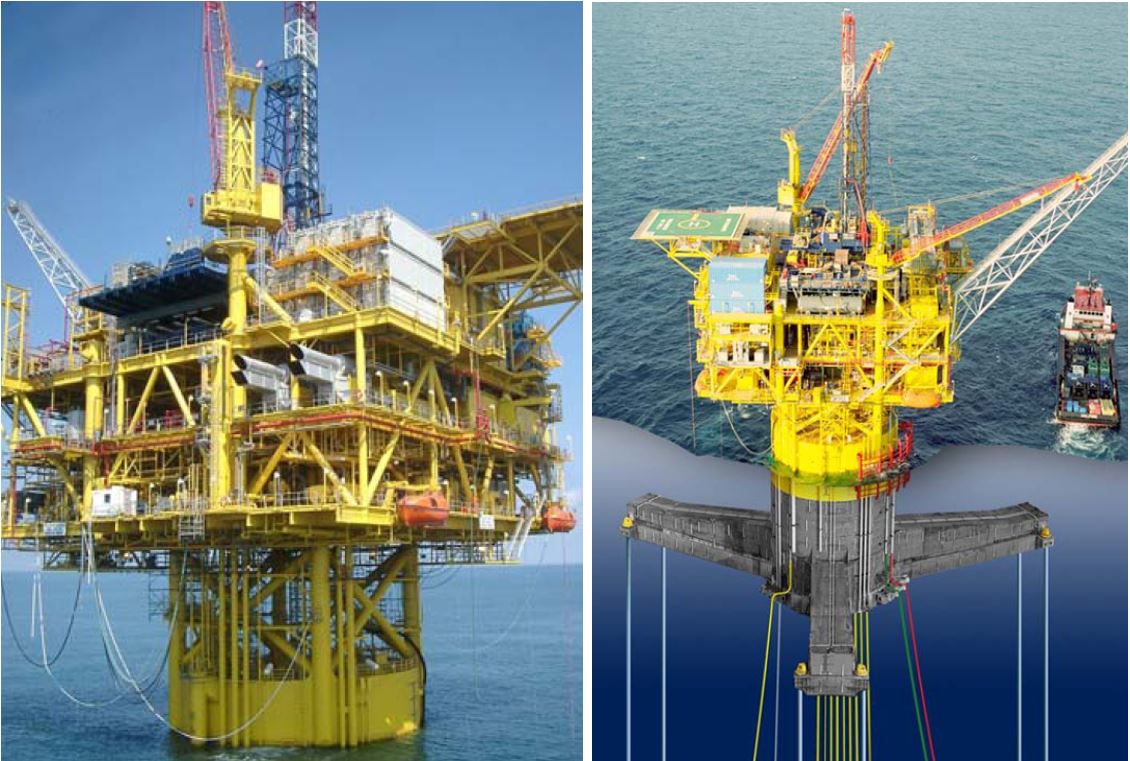
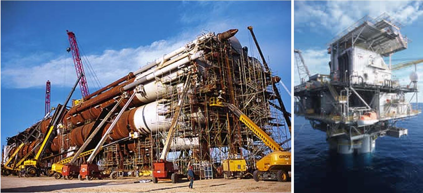
3.6.4 Matterhorn Project
The Matterhorn field (W&T Energy) is located in the GOM in Block Mississippi Canyon 243 by around 860m water depth.
The development features a SeaStar Mini-TLP with surface trees. Matterhorn is the first application of such platform with surface trees. The dry tree development was deemed as the best economical choice due to the number of stacked reservoirs that would have required well work to shift production from one zone to the other.
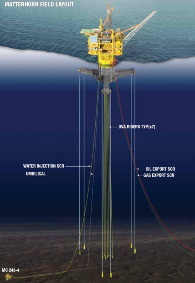
The development plan requires a total of 8 wells, all to be dry trees except for one water injection subsea well, as its distance from the platform do not allow drilling from the central location.
The seven surface trees are connected to the wells by 9" or 10" vertical tensioned risers. The subsea water injection tree is connected to the platform by a 6" catenary riser. Oil and gas export are done respectively through an 8" and a 10" pipeline, using SCRs to connect them.
The primary function of the TLP is to serve as a production and workover platform utilising both dry trees and subsea wells.
The platform can accommodate up to 9 dry trees (7 have been installed), with vertical top tensioned risers, and has capacity for up to 5 subsea tie-backs. The TLP supports facilities for workover on the wells, subsea well control, processing oil/gas production (to 'export' quality), exporting production through pipelines and living quarters.
The mini-TLP features a single column with central moonpool for the surface tree risers. Three pontoons radiate from the bottom of the column, each of them supporting two tendons at their extremity. The TLP also includes a three-level deck supported above the column by a jacketed structure (Figure 3.16, “Matterhorn TLP”).
The TLP has been temporarily equipped with a 1000HP rig, which was used to complete the wells. All the wells were pre-drilled prior the platform installation.
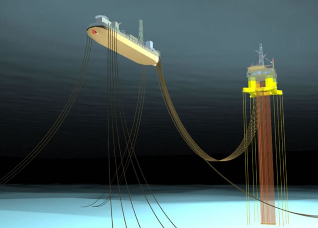
3.6.5 Kizomba A and B developments
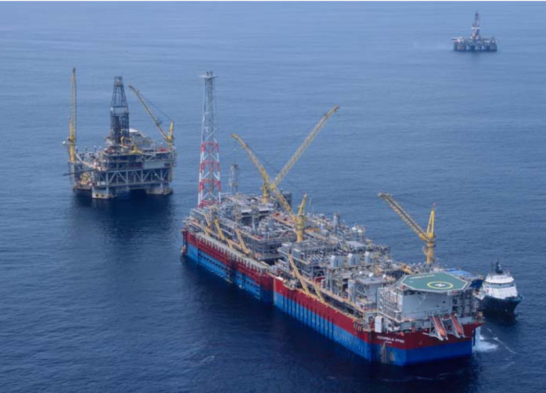
The Kizomba A and B projects (ExxonMobil, Angola) incorporate each a TLP supporting dry trees (referred as Surface Wellhead Platform or SWHP). The development consists of the TLP being close-moored to a spread-moored FPSO in around 1100m water depth (Figure 3.17, “Kizomba A TLP close-moored to an FPSO”). Fluid transfer lines in ‘double-catenary’ configuration connect the two floating structures. The development also includes offloading facilities and subsea wells (refer to Figure 3.18, “Kizomba A Field Development Scheme (ExxonMobil, WOA)”). The processed crude is stored in the FPSO and periodically offloaded to tankers by the offloading surface floating buoy system.
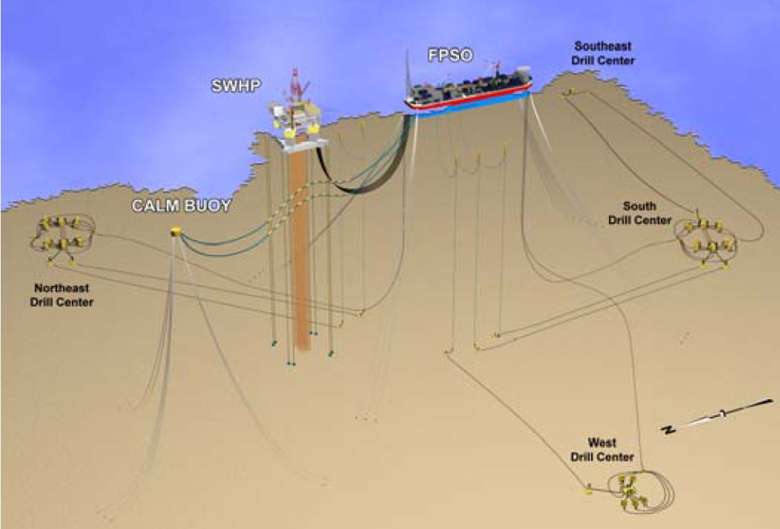
The Kizomba A full field development plan calls for 54 wells. All production wells are surface wells, drilled and completed from the TLP.
Some of the gas and water injection wells are also surface wells, while the others are subsea wells, drilled and completed from a MODU, and tied-back to the FPSO (Figure 3.18, “Kizomba A Field Development Scheme (ExxonMobil, WOA)”).
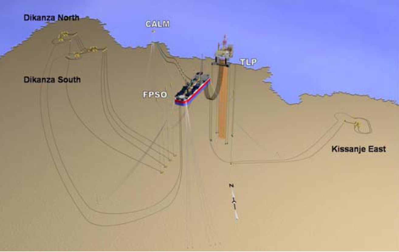
The Kizomba B development plan requires 46 wells. It is similar to the Kizomba A architecture, but some of the production wells are subsea wells connected to the FPSO (Figure 3.19, “Kizomba B Field Development Scheme (ExxonMobil, WOA)”).
The primary functions of the TLP are providing platform drilling and supporting surface production trees and a limited number of injection trees. The topsides comprise a self-contained platform drilling system and full well-stream manifolds, but no processing equipment. Dedicated lines transfer the produced fluids from the TLP to the FPSO. Permanent power is supplied to the TLP by the FPSO through a suspended power cable. Generators installed on the TLP deck provide back-up power during the field life and were used prior the installation of the FPSO.
The FPSO is a spread-moored new-build vessel. It has processing capacity for 250,000 barrels of export quality oil per day. Prior the export by tankers, the oil is stored in the FPSO, which features a 2.2 million barrels of oil storage capacity. The produced gas is compressed and dehydrated to provide fuel gas and gas lift, the surplus being re-injected in the reservoirs.
The export system consists in a loading buoy (CALM type) anchored around 2km from the FPSO. The connection is performed by means of two 20" steel export pipelines in 'wave' configuration.
3.6.6 Moho Nord development
Moho Nord was designed to simultaneously develop the reserves of the two geologically distinct environments found in the northern part of the Moho Bilondo PEX (exploitation license):
To meet this challenge, Moho Nord is Total's only deep offshore development that pairs two kinds of floating structures: an PU (Floating Production Unit) and a TLP (Tension Leg Platform). The two structures stand 350 m apart in around 780m water depth and are connected by six transfer lines. They operate two different production systems.
The TLP accesses the Albian carbonate reservoirs with surface Christmas tree wells installed on the TLP, whose multiphase production is being directed to the PU.
Likouf is the first PU in the Congo to process two different kinds of oil: Albian light oil (33° API, 0.8 cP) and Miocene oil, which is heavier (18° to 25° API) and more viscous (4 to 13 cP). Both are processed at the facility on two parallel systems. The final stages of processing take place in the hull, where the oils are dehydrated by decantation in separate wash tanks. The oils are then combined prior to being desalted and exported to the Djeno oil terminal on the coast.
The TLP is designed with 27 drilling slots while the subsea network includes 17 horizontal wells (11 production and 6 water injection wells). Moho Nord development incorporates 199 km of underwater lines (145 km of rigid pipe, 17 km of flexible pipe, 37 km of umbilicals, including 4 km of transfer lines between the PU and the TLP) and a 76km oil export line to the Djeno terminal.
TLP (Tension Leg Platform) was selected due to the Albian carbonates specificities (very low matrix permeability and oil prone to asphaltene precipitation) which require frequent interventions (well stimulation via acid injection, anti-depositing treatments) by operators to maintain satisfactory productivity over the full operating life of the wells.
Surface Christmas tree wells are drilled from the TLP, using a non-permanent rig installed on the TLP supported by a floating assistance structure. The derrick and coiled tubing for working on the wells have been designed specifically for Moho Nord to enable interventions simultaneously with drilling operations.
Likouf all-electric PU (maximum production capacity of 100 000 bopd) controls, processes and exports all production from the Miocene (subsea wells) and Albian (surface Christmas tree wells) reservoirs. This is an all-electric PU to reduce the gas combustion needed to generate power: this electrical power is provided by three turbine generators (3 x 26.67 MW) fuelled by the gas associated with oil production.
Moho Nord was the first development in the Congo with no gas flaring under normal operating conditions, and to re-inject the entirety of the produced waters.
3.7 Spar Based Development
3.7.1 Main Features
Spars have been used in water depths up to 2383m ("Perdido"). They use catenary or taut moorings which allow them to be relatively insensitive to water depth. They are adapted to dry tree applications and their vertical risers can be tensioned by means of air cans so their tension is decoupled from the floater. Spars are hence well suited to very deep water applications. They feature a sheltered centre-well for the riser protection (against environmental loads) and guidance (i.e. related to clashing issues) in the wave action zone.
On the other hand, the riser air can tensioning system could restrain the number of risers that can be accommodated. However, up to 25 vertical tensioned risers have already been accommodated on "Kikeh" for the current applications.
Platform wells may be drilled by MODU even after the Spar is in-place. This can avoid the requirement for an integrated drilling rig. Among the existing Spars, around half support full drilling equipment.
Only few Spars produce through subsea wells and hence do not support any drilling/workover facilities (Red Hawk, Tahiti, Aasta Hansteen, Lucius, Heidelberg, Perdido, …).
3.7.2 Red Hawk Field
The Red Hawk field is a deepwater gas field located in GOM. It has an estimated 250 Bcf of gas reserves. The field development consists of a cell Spar moored in 1615m of water and two 5" lines/SCRs connecting two subsea trees. An export gas pipeline, connected to the floater by an SCR, routes condensate and gas to processing onshore facilities (Figure 3.21, “Red Hawk Field Development”).
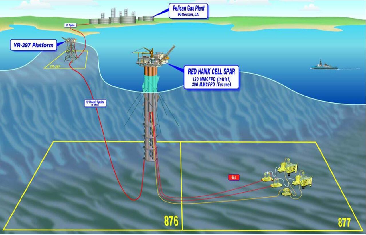
The initial development scheme for this 250 Bcf gas reserve field was a subsea long distance tie-back to another host platform. But it was finally deemed as an economical advantage to have a hub that could be used to tie-back (in addition to the Red Hawk field) future production that could be developed in the geographical vicinity.
The Red Hawk development features the use of the world's first Cell Spar. The main improvement of this third generation of Spar is the fabrication method, which allows (1) a greater percentage of the work to be performed using repetitive operations (multiple similar 'tanks' instead of one huge cylinder) and (2) the possible split of the fabrication between different locations prior the final assembly (refer to for further details on the Spars).
It is also the first Spar utilisation for a full subsea development. Although the other Spars have allowance for production through subsea wells, most of them are primarily surface tree facilities.
The platform is moored by means of six taut mooring lines (including polyester segments). The topsides have three decks. The facilities are designed for a production of 120 MMcf/d with the potential to add production train to handle up to 300 MMcf/d of gas and 20,000 b/d of oil.
All the risers are SCRs, installed and guided through pull tubes. The Red Hawk field itself requires two 5" steel risers for initial production, one umbilical (connected to the subsea wells) and one export steel riser/pipeline. Provisions are included for a second identical gas subsea development and for a series of two PIP risers for future oil production.
3.7.3 Kikeh Field
The Kikeh field is operated by Murphy Oil Corporation. It is the first deepwater project developed in Malaysia (production started in September 2007).
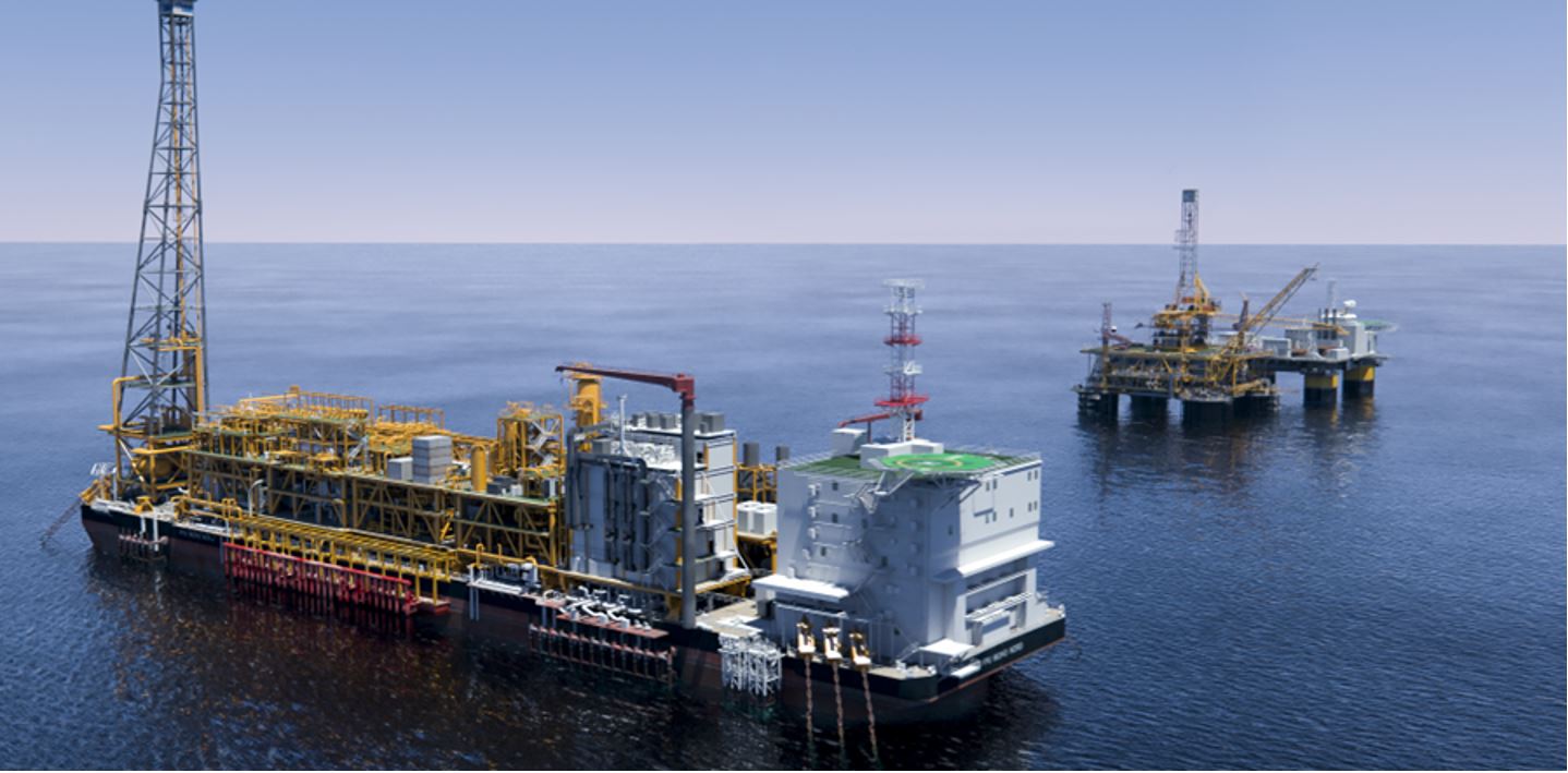
The field lies in 1300m water depth at 210 km from Kota Kinabalu, the state capital of Sabah on Borneo. The development includes a truss spar, which serves as a surface wellhead support platform, and a FPSO for further processing and storage. Initial production of 20,000 b/d of oil ramped up to 120,000 b/d at the end of 2008.
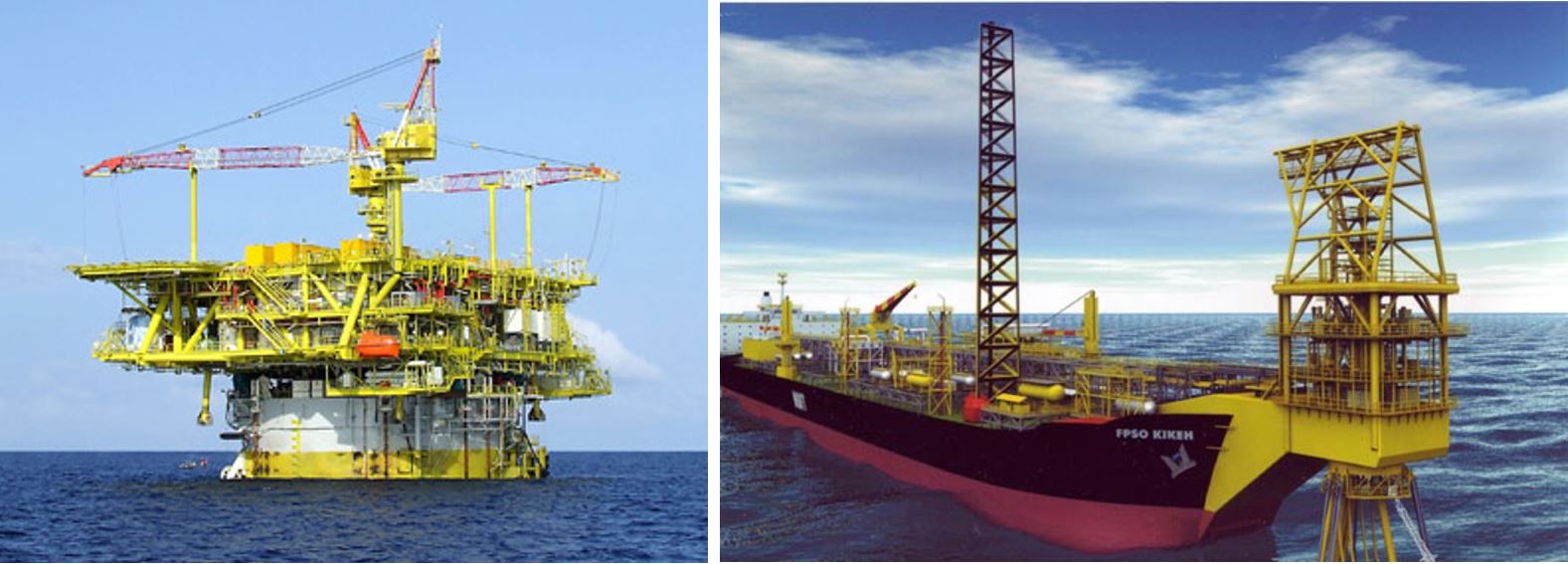
The Technip's Spar is 142m long and 32m in diameter. It is fitted with 3,400tonnes topsides, providing a 25 slots wellbay for dry tree wellheads. It incorporates a tender assisted drilling rig to drill and complete the Kikeh wells.
The FPSO is a converted tanker with a storage capacity of two million barrels. The FPSO is designed to accommodate an oil production at a rate of 120,000bpd and water injection at 260,000bpd water. It can compress gas at 3.8 million m3 a day. It is fitted at the bow with an external turret to accommodate up to 17 flexible risers ranging from 8in to 10in in diameters (nine risers to start with, four in the future, three umbilicals and one spare).
The two floaters are connected by transfer lines, based on the SBM Gravity Actuated Pipe system (see Section Section 3.5, “Fluid Transfer Lines”).
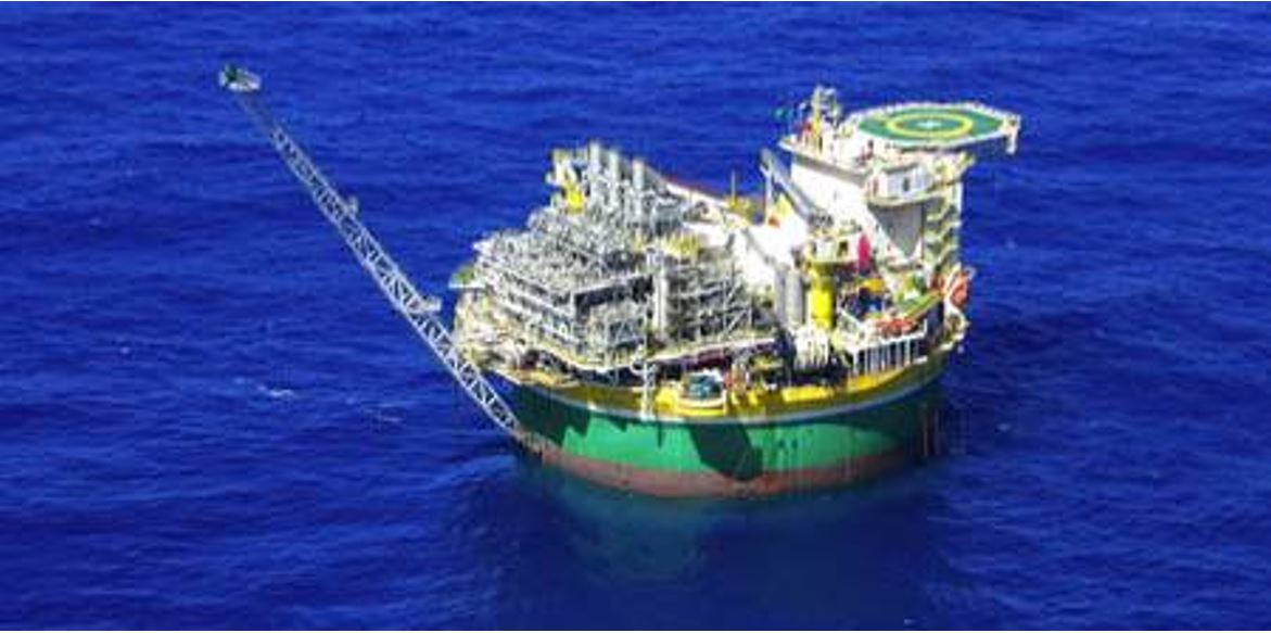
3.8 FPSO Based Development
3.8.1 Main Features
The existing FPSO are associated to subsea development schemes and drilling/workover derrick is still at research and development phase, e.g. Floating Production Drilling Storage & Off-loading (FPDSO) vessel.
The FPSO features unique oil storage capacity with regard to the other hull forms, which is often the primary reason for its selection. A screening of the existing facilities (refer to ) shows that the FPSO is generally chosen in regions where oil fields are remote from refining infrastructures, including West of Africa and parts of Asia Pacific.
Another important feature of FPSOs (shared with the semi-submersibles) is that they can be converted from existing hulls, e.g. VLCC tankers. Their ability for conversion and reuse allow them to be well suited for short assignment, including early production system (EPS, refer to Chapter 2, Field Development strategy ) and extended well test (EWT). They are also particularly adapted to small/marginal fields, due to their reuse ability and their inherent feature of storage and tandem offloading to tankers of opportunity; avoiding an export pipeline.
| Tip Click these links below for access to 3D resources: |
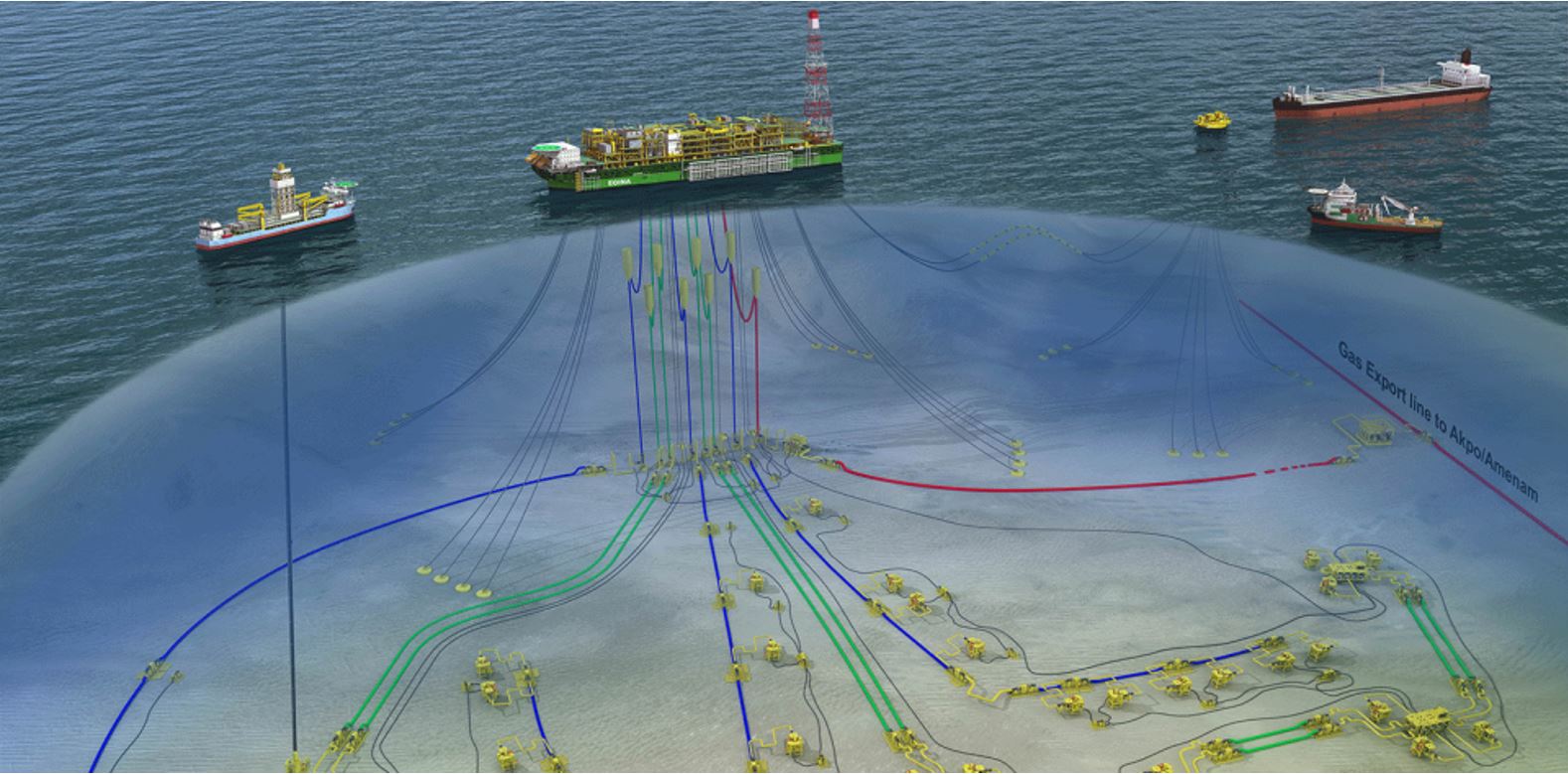
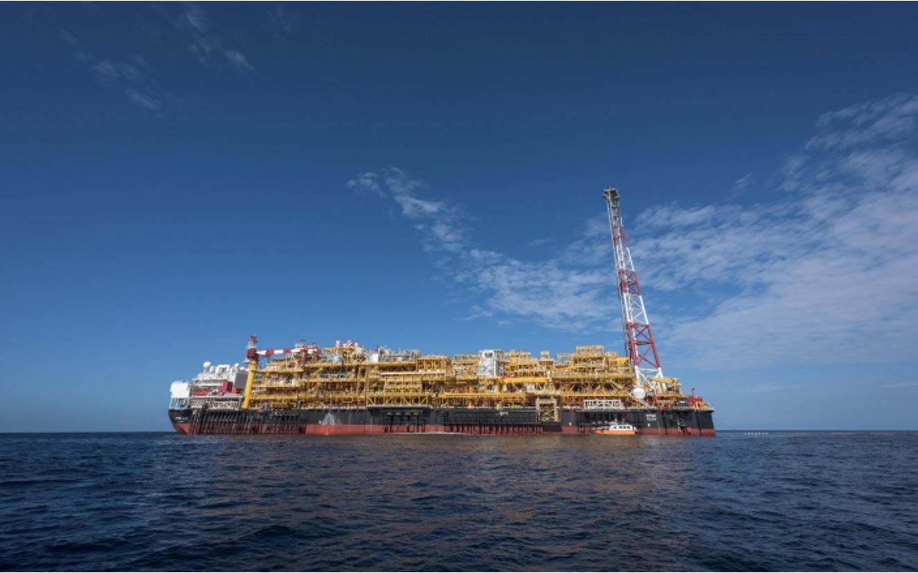
3.8.2 Egina Field
Discovered in 2003, the Egina field is located at water depths of between 1 400 and 1 700 meters, 200 km offshore from Port Harcourt. It is operated by Total, in partnership with NNPC, CNOOC, Sapetro and Petrobras.
The development consists in a subsea production system connected to a FPSO (floating production, storage and offloading vessel) designed to hold 2.3 million barrels of oil. Weighing close to 220,000 metric tons and measuring 330 meters long by 60 meters wide, the Egina FPSO is the largest ever built by Total. The FPSO is connected to 44 subsea wells 1,600 meters deep and will produce 200,000 barrels of oil per day. The produced oil is exported through two unbonded flexible oil offloading lines connecting the FPSO to the offloading buoy.
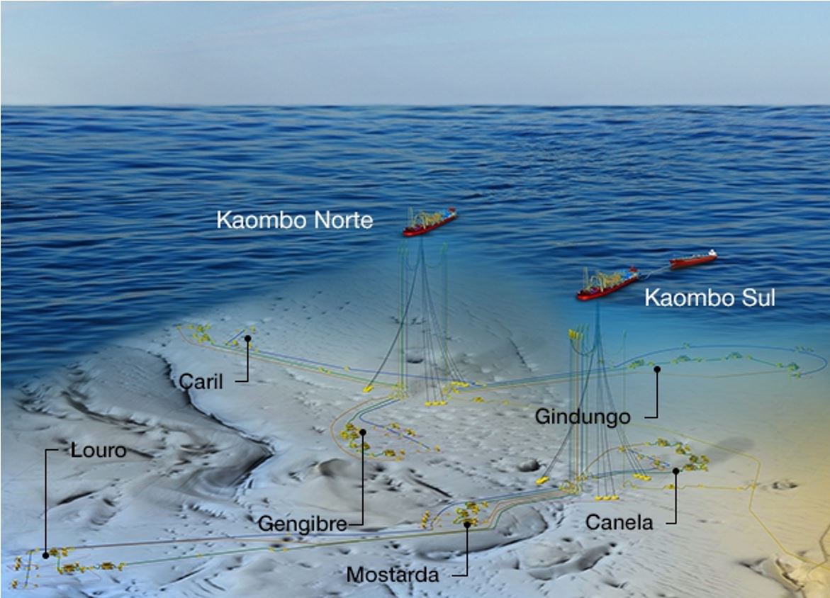
3.8.3 Kaombo Field
The Kaombo field, operated by Total, is located in Block 32, 150 km offshore Angola, at water depths ranging from 1 425 m to 1 950 m.
The objective of this project is to tap into the oil deposits spread across six fields, connected via 300 kilometers of subsea pipelines to two floating production, storage and offloading (FPSO) vessels: Kaombo Norte and Kaombo Sul.
This massive, complex project has some unique characteristics:
Water depths reaching up to 1 950 meters,
Kaombo’s reserves, estimated at 658 million barrels, for a production capacity of 230,000 bopd,
Particularly complex production system required to tap into oil deposits spread across six fields, covering a surface area of 800 square kilometres.
Kaombo required the installation of 59 wells, making it the largest subsea well system in Angola for a single project. Some 300 kilometers of subsea pipelines now enable the six groups of reservoirs to be tied back to two FPSO units. Two oil tankers were converted into FPSO units with internal turret.
The first FPSO, Kaombo Norte, will develop three of the six fields – Gengibre, Gindungo and Caril – and the second FPSO, Kaombo Sul, the other three – Canela, Mostarda and Louro. Kaombo Norte produced first oil in 2018, and Kaombo Sul is scheduled to produce first oil in 2019. Once operational, each vessel will produce and store up to 115,000 bopd.
3.8.4 CLOV Field
TOTAL CLOV field is located off the coast of Angola, in water depth ranging from 1 100m to 1 400m, and comprises four oil fields: Cravo, Lirio, Orquidea and Violeta. Two types of oil – one more viscous than the other – are simultaneously extracted, and field’s reserves are estimated at 505 million barrels.
Subsea wells are connected to a Floating Production, Storage and Offloading (FPSO) unit. Measuring 305 meters long and 61 meters wide, the FPSO is a new built vessel with a storage capacity of 1.8 million barrels of oil, held on site with a spread of sixteen mooring lines.
CLOV subsea development consists of a total of 34 subsea wells, 8 manifolds and one multiphase pump system, 38 km of production lines, 57 km of water injection lines, 84 km of umbilical, 32 km of gas export line, two Hybrid Riser Towers and one Single Hybrid Riser for the gas export. A subsea multiphase pump system will be used deep offshore to enable production of two different oil qualities from the oligocene reservoirs and the more viscous miocene reservoirs.
The gas produced on CLOV is exported via a subsea line to the onshore Angola LNG liquefaction plant.
CLOV came on stream in June 2014, and reached its production plateau in September 2014.
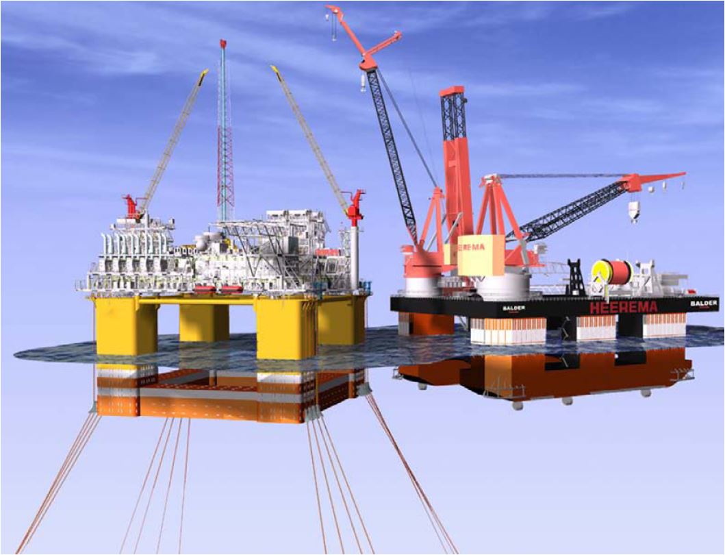
3.9 Semi-Submersible Based Development
3.9.1 Main Features
The semi-submersibles do not need to be purpose-built for the field and can be drill-rig converted. Similarly to the FPSOs, they are suited for conversion and reuse, which allow them to be adequate for short assignment, including EPS (refer to Chapter 2, Field Development strategy ), extended well test (EWT) and marginal fields.
In some deepwater area (e.g. Brazil, GOM), very large semis have been used. They are capable to support a significant number of risers hung off the deck edges or pontoon and are adequate for high production rate. They are also adapted to ultra deep water applications due to their catenary and taut mooring lines.
3.9.2 Na Kika Field
The BP Na Kika project (GOM) is a subsea development of different independent fields tied-back to a centrally located semi-submersible host facility. The development is located in water depths ranging from 1770m to 2300m. The total recoverable hydrocarbons are approximately 300MMboe. The subsea system features 12 subsea wells connected to the floater via flowlines and SCRs. The produced effluent is exported through dedicated 18" oil and 20" gas pipelines.
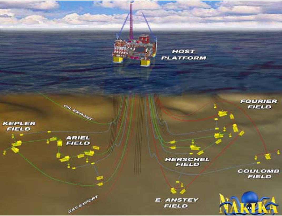
The semi-submersible is moored on location by means of 16 semi-taut catenary mooring lines. The topside facilities mainly consist of inlet separators for each subsea field, complete separation, dehydration and treatment facilities for oil process up to 110,000 bpd, gas handling facilities to process up to 12 million m3/d, water handling facilities for 7,000 bpd, gas turbines and living quarters (63 people). In addition, Mono-ethylene glycol and tri-ethylene glycol facilities are used to prevent hydrate formation in the gas loop and gas export pipeline.
3.10 SSP based Development
Sevan Stabilised Platform (SSP) is a cylinder shaped platform type for floating production, storage and offloading of oil and gas, Ref. [9]. The SSP is a variant of the ship-shaped FPSO and is basically a mono-hull with circular shape. The circular shape dispenses the unit of any heading changes and consequently, the SSP does not need turrets or swivels. The SSP functions and capacities are basically the same as for a medium-ranged FPSO type floaters and follows the same development principles.
Goliat FPSO, owned and operated by Vår Energi AS, has been in operation in the Barents Sea since 2016. Its SSP design included a 90m hull diameter and 25 riser slots, a storage capacity of 950,000 bbls and an oil production capacity of 100,000bopd.
3.11 Subsea Tie-back
3.11.1 Main Features
The increasing use of subsea production technology and its maturity now allows developing fields in a full subsea tie-back solution, associated with existing host facilities, new facilities or even for direct tie-back (i.e. gas & condensate) to shore based facilities.
The incentive for such development scheme is to reduce the overall capital expenditure by utilising processing capacity on existing infrastructure (or sharing new infrastructure between different developments) rather than building complete new structures for every field. Hence, much smaller accumulations could be developed economically.
The technical challenges of such developments are related to flow assurance issues and hence are governed by whether the satellite field is an oil or gas producer. While both types may feature hydrate and corrosion management issues, an oil production system may also involves wax, asphaltene, scale and emulsion issues. Extending the tie-back distance of gas producer is hence more straightforward. Gas systems can be allowed to cool down while an adequate flow of inhibitors is maintained throughout the line.
Oil systems are much more reliant on the efficiency of the insulation, which features however an intrinsic limitation in term of offset distance. Two ways are currently investigated to overcome the actual offset limitations: the heating systems (refer to for further details) and the subsea processing, i.e. the use of subsea pumps to boost either the raw effluent or separated fluids (Ref. ).
Gas field reservoirs tied-back to shore are much more reliant on gas compression to give the production profile a lengthy tail, e.g. Statoil/Norsk Hydro Ormen Lange (now Shell).
3.11.2 Ormen Lange Long Distance Tie-back
The Ormen Lange Field lies at water depths ranging from 850m to 1100m offshore Norway. It has expected recoverable gas reserves of 397 billion Sm3 and 28.5 million Sm3 of condensate, i.e. the second largest gas field in Norway (i.e. Snøhvit production start-up May 2007). The expected production peak is around 22 billion Sm3 per year (production start-up September 2007) and the field life has been evaluated to 30-40 years.
Ormen Lange is developed as a long tie-back field to onshore gas processing facilities at Nyhamna, i.e. 120km from the production wells.
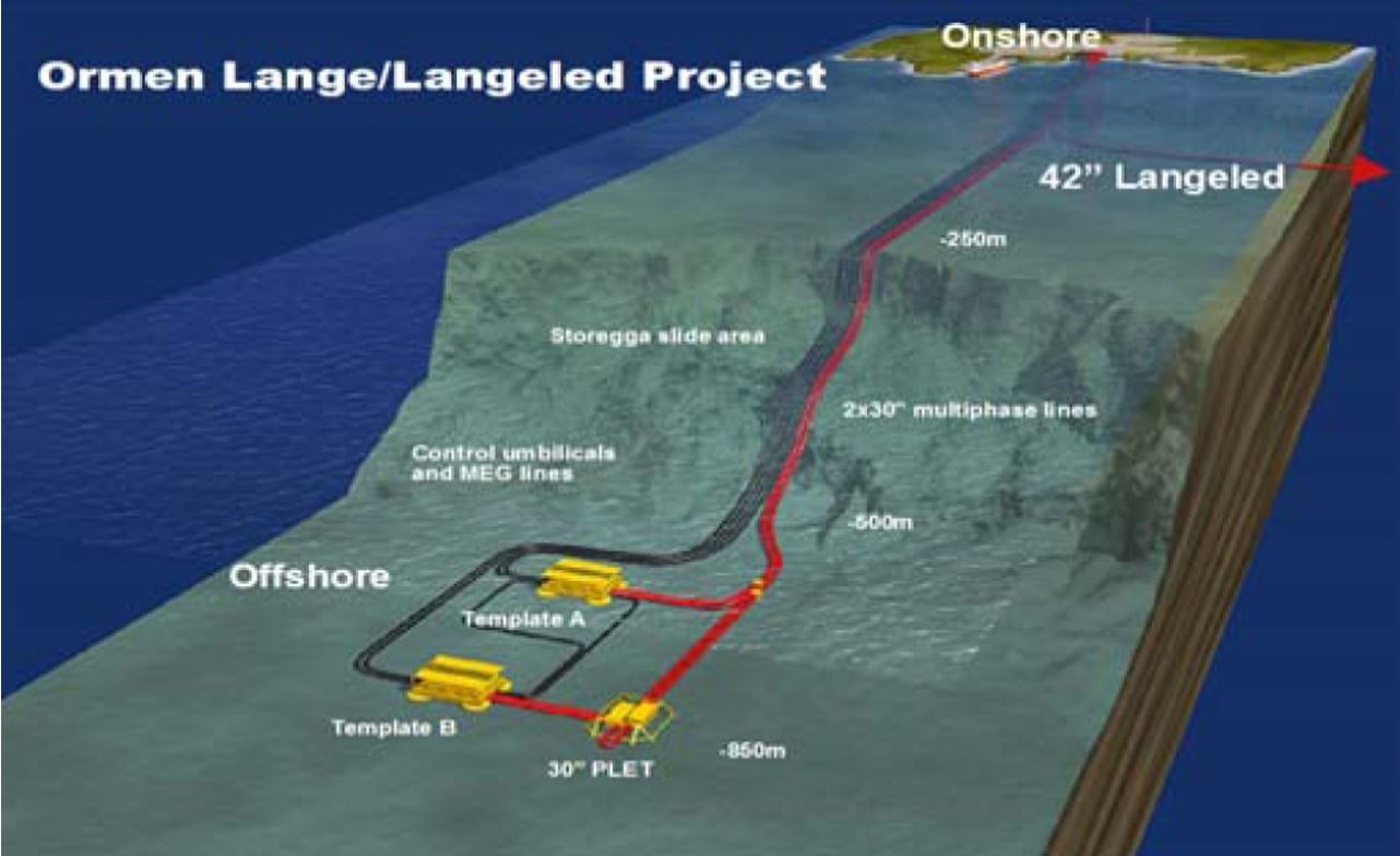
The gas is produced from 19 subsea wells divided between four 8-slot production templates (1150t each). The fluids are directly transported to the Nyhamna facilities through two 30" multiphase lines. Four main control umbilicals link the onshore facilities to each template (with a crossover umbilical connecting both templates for redundant hydraulic supply). The wells are continuously injected with mono-ethylene glycol (for hydrate prevention) via 6" pipelines from the onshore plant.
After a close cooperation with suppliers and partners with a focus on optimizing work volume, costs, safety, environment, and using learning from similar projects, Shell has chosen subsea compression as a concept for the third phase of the Ormen Lange field development. This option has been preferred compared to other alternatives, such as unmanned platform solutions and several subsea concepts.
At the time of this report’s preparation, two options for subsea compression were still contemplated: one for wet gas developed by OneSubsea and built on technology installed on Gullfaks, and a wet gas-tolerant system from TechnipFMC, which is based on experiences from the Åsgard field. Both of these options will need power from land.
The choice of underwater concept is expected later in 2019, followed by investment decision in the Ormen Lange license.
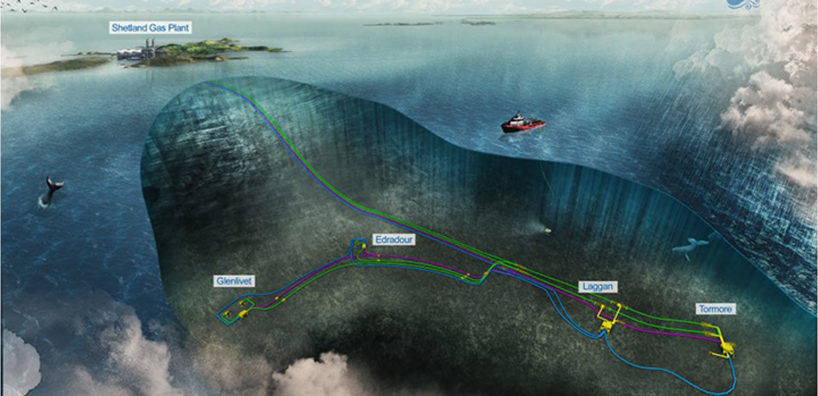
3.11.3 West of Shetland gas project
The West of Shetland project encompasses three innovative projects combined into one:
Laggan-Tormore,
Onshore Shetland Gas Plant,
Edradour-Glenlivet.
This TOTAL project represents the first-time use of subsea-to-shore technology. The aim of this new development method is to install the entire production system directly on the seabed and thus completely eliminate the need for offshore surface infrastructure. The use of these subsea production systems enables to go further offshore, in deeper waters (3,000 meters and more) and in harsher conditions (pressure, temperature, ocean currents), while improving installation safety and reducing costs.
Laggan-Tormore: a 600-meter-deep offshore gas project
Discovered in 1986 and 2007 respectively, the Laggan and Tormore fields are located off the Shetland Isles. Despite a steep drop-off from 120 to 600 meters and more below sea level, the longest subsea-to-shore system ever seen in the North Sea has been installed. Four wells have been drilled in some of the deepest and coldest waters in the United Kingdom, and tied back to a new gas processing plant on the Shetland Isles via a 140 kilometer pipeline network. Production began in February 2016.
Onshore Shetland Gas Plant
Located on the north coast of the main island of the Shetland Isles, the Shetland Gas Plant was built to process gas from the Laggan-Tormore wells. When the production fluids arrive onshore, the liquids (condensates) are removed and piped to the nearby Sullom Voe oil terminal, while the gas is processed before being piped across the United Kingdom. The Shetland Gas Plant currently supplies around 8% of the UK’s total gas consumption, representing enough gas for two million households.
Edradour-Glenlivet: an extension of the subsea gas project
West of Shetland took on a new dimension in August 2017, when two new fields – Edradour and Glenlivet – came on stream. The two fields lie some 75 km and 90 km north west of the Shetland Isles, in water depths of 295 meters and 435 meters respectively. The project consists of three wells tied back to the existing Laggan-Tormore production system, which exports the gas to the onshore Shetland Gas plant.
The West of Shetland project has a production capacity of 90 thousand barrels per day.


