
Subsea Control System | T084-EN005 | |||
REVISION 05 | STATUS C | |||
 |
| 05 | 17/04/19 | JSO | Approved | CGA | VLE | - | HEK |
| 04 | 01/03/19 | JSO | Re-Issued for Approval | CGA | VLE | - | HEK |
| 03 | 12/02/08 | KSL | Approved | GCO | AAL | BCA | - |
| 02 | 06/02/08 | KSL | Issued For Approval | GCO | AAL | BCA | - |
| 01 | 04/10/07 | KSL | Issued For Comments | GCO | AAL | BCA | - |
| 00 | 01/10/07 | KSL | Internal Check | GCO | AAL | - | - |
| Rev. | Date | Issued by | Revision memo | Checked by | Approved by | ||
|---|---|---|---|---|---|---|---|
| Engineer approval | Total approval | ||||||
Contents
- 1. introduction
- 2. Control System Types
- 3. Reliability and Redundancy
- 4. Open/Closed Hydraulic Systems
- 5. System Architecture
- 6. System Outline
- 7. Master Control Station (MCS)
- 8. Electrical Power Unit (EPU)
- 9. Un-Interruptible Power Supply (UPS)
- 10. Hydraulic Power Unit (HPU)
- 11. Topsides Umbilical Termination Unit (TUTU)
- 12. Umbilical
- 13. Subsea Umbilical Termination Unit (SUTU)
- 14. Weak Link
- 15. Subsea Distribution Unit (SDU)
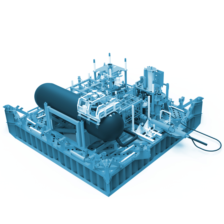
- 16. Subsea Accumulator Module (SAM)
- 17. Interconnections
- 18. Subsea Control Module Mounting Base (SCMMB)
- 19. Subsea Control Module (SCM)
- 20. Subsea Transducers/Sensors
- 21. Multi Phase Flow Meters
- 22. Materials
- 23. Markings
- 24. Quality
- 25. Running Tools
- 26. Factory Acceptance Testing (FAT)
- 27. Extended Factory Acceptance Test (EFAT)
- 28. System Integration Testing (SIT)
- 29. Alternative Control Systems
- 30. High-Integrity Pressure Protection Systems (HIPPS)
- A. Authors & Vendor Contact Details
List of Figures
- 2.1. Direct Hydraulic Control System
- 2.2. Piloted Hydraulic Control System
- 2.3. Electro-Hydraulic Control System
- 2.4. Electro - Hydraulic Multiplex Control System
- 2.5. K5F all electric subsea xmas tree
- 2.6. OneSubsea DC Subsea Electric Tree
- 3.1. CLOV – Orquidea Violeta subsea layout
- 5.1. KAOMBO – SSIV assembly
- 5.2. KAOMBO – SSIV retrievable module
- 6.1. Subsea Control System overview
- 6.2. Electro - Hydraulic Multiplex System Schematic
- 7.1. Dual MCS
- 7.2. ESD Radio Link Block Diagram
- 7.3. Typical Tree mimic
- 7.4. Typical Manifold mimic
- 7.5. Choke pawl and ratchet mechanism
- 7.6. Choke command circuit
- 7.7. Historical information typical display
- 8.1. Typical EPU
- 8.2. EPU cabinets A and B (Moho Nord)
- 8.3. EPU input monitor module (Moho Nord)
- 8.4. EPU Subsea Controller (Moho Nord)
- 8.5. EPU Modules
- 9.1. Typical UPS
- 10.1. Hydraulic Power Unit
- 10.2. Internals of HPU skid unit
- 10.3. HPU Schematic
- 10.4. HPU interfaces
- 11.1. TUTU Umbilical Termination
- 11.2. TUTU Block Diagram
- 11.3. Inside a typical TUTU
- 14.1. Weak Link
- 15.1. A typical SDU (OneSubsea design)
- 16.1. Subsea Accumulator Module Block Diagram
- 16.2. Subsea Accumulator Module
- 17.1. SDU Fixed Stab plates
- 17.2. Outboard and Inboard Stab plates shown before engagement
- 17.3. Outboard and Inboard Stab plates
- 17.4. FLOT (left picture) / TDU (right picture)
- 17.5. ROV Stabplate with HFL connected
- 17.6. Controlled Environment (CE) connector (by courtesy of Tronic)
- 17.7. Electrical jumper with Tronic ROV connector
- 17.8. Single Electrical Jumper with three outlets
- 17.9. EFL connector unmated (left) and mated (right) (TELEDYNE ODI connector)
- 17.10. EFL connector (dual oil-filled) - connection sequence (TRONIC DigiTRON connector)
- 17.11. SpecTRON 10kV (U) 450A Connector Systems (SIEMENS)
- 17.12. SpecTRON Connector Systems (SIEMENS)
- 17.13. Hydraulic Couplers (Parker DSL series)
- 17.14. Pressure Balanced Hydraulic Coupler Concept
- 17.15. HCR Hose & Termination Cross Section
- 17.16. Female / male Walther couplers with R1 profile (MeOH)
- 17.17. Subsea disconnectable Fibre Optic Connectors (Seacon hydralight product)
- 17.18. Fibre Optic Connectors at bottom of SCM mounting base
- 17.19. Hydraulic Jumper Deployment Frame
- 17.20. Electrical Jumper Deployment Frame
- 17.21. Electrical Jumper Deployment Basket
- 17.22. EFL pre-installed on cobra head
- 17.23. EFL pre-installed on Manifold (Moho Nord M1001 manifold)
- 18.1. OneSubsea design SCMMB
- 18.2. SCM & SCMRT being lowered on to manifold SCMMB
- 18.3. SCM & Running tool being lowered into the Manifold guide funnel
- 18.4. SCM Running tool (Aker Solutions)
- 19.1. OneSubsea design Subsea Control Module
- 19.2. FMC design Subsea Control Module
- 19.3. View under SCM showing hydraulic couplers and electrical connectors
- 19.4. Manifold block and DCV’s
- 19.5. DCV (Oceaneering ROTATOR AS)
- 19.6. DCV cross section (Oceaneering ROTATOR AS)
- 19.7. SCM showing Subsea Electronics Module (OneSubsea)
- 19.8. Subsea Electronics Module (GE)
- 20.1. Typical PT/TT sensor (GE Asterix product)
- 20.2. Typical 4-20mA Sensor Loop
- 20.3. Typical Sensors
- 20.4. Retrievable PT/TT sensor installed subsea (TECHNIPFMC Water Injection Xmas Tree of EGINA Development)
- 20.5. Combined Pressure / Temperature Transducer
- 20.6. Acoustic Sand Detector
- 21.1. Subsea multiphase flowmeter with recoverable electronic canister (in blue) (Emerson ROXAR MPFM)
- 21.2. MPFM Dynamic testing with pressurised process medium
- 21.3. Measurements block diagram
- 23.1. Identification Plates
- 23.2. Stencil Painted Markers
- 23.3. Colour Keyed Identification
- 23.4. Cable Markers
- 25.1. PXT SCM recovery - MRT with ROV
- 26.1. Subsea sensor simulator
- 29.1. East Spar Buoy
- 29.2. Autonomous Control System Schematic
- 29.3. Oil Filled Jumper with Fibre Management System
- 29.4. Subsea Fibre Optic Distribution
- 29.5. Control System Infrastructure
- 29.6. Functional Architecture
- 30.1. HIPPS Schematic


