23 Markings
23.1 Equipment Marking
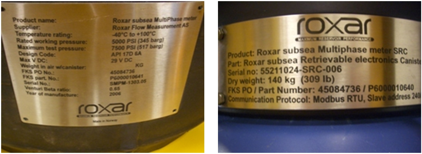
Subsea control system deliverables are delivered as individual items and to different locations. Each part has a Manufacturer's part number and a serial number. The part number identifies the assembly through the manufacturing process and for re-ordering, and the serial number gives unique traceability through the assembly and testing, and for material traceability.
This provides a formal and acceptable method of tracking part numbers back to the design documents, and for installation on Xmas trees, manifolds, etc.
In addition to the Manufacturer's own identification system, each unit in the system will also have an Equipment Number, allocated by the Customer or overall Contractor, which enables all Topside and Subsea equipment to be identified for overall control of the offshore installation.
In addition, all subsea valves and instruments are allocated a Tag Number, which identifies their function and, again, enables them to be identified on an overall offshore -installation database and on the overall P&ID.
It is important to define Equipment and Tag Numbers at an early stage in the project to ensure all items and drawings use the same information, to avoid confusion. The process of developing Tag numbers and a tag numbering procedure is always time consuming and complicated since there are several interfaces involved, however the timely completion of the database of tag numbers is crucial, since the development of the MCS software and system P&ID’s cannot be finalised without it.
Furthermore, hydraulic and electrical signals used throughout the system are usually identified by the Manufacturer as part of its own overall System Block Diagram, to uniquely identify each signal throughout the system For example, LPA, LPB, HPA, and HPB to identify low/high pressure dual-redundant channels. Where equipment such as the subsea control module mounting base (SCMMB) requires hooking up to the Xmas tree actuator tubing by third-party installation contractors or manufacturers, the hydraulic connections will have hydraulic interface connections stamped onto the connection plate.
23.2 Subsea Marking General
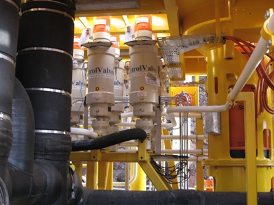
When subsea controls equipment is to be hooked up subsea, there is a need for clearly visible markings, which can be identified by the video camera from the ROV.
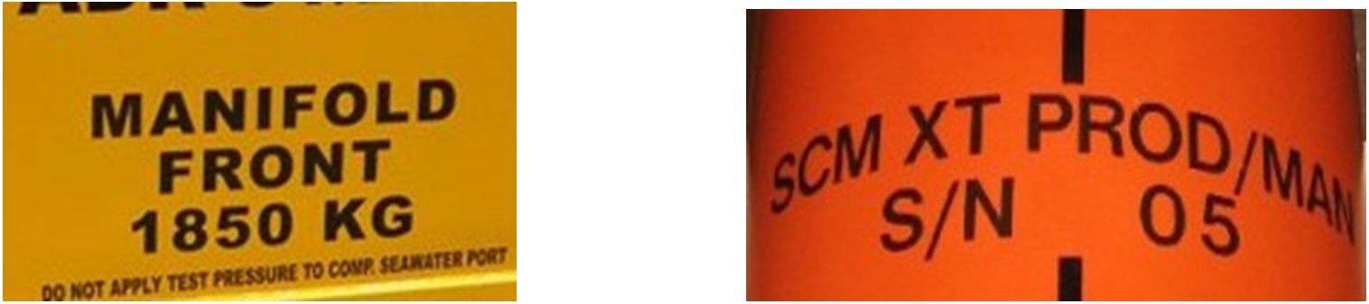
Equipment such as subsea control modules (SCMs) need clear identification of the service (e.g. Production, Water Injection), the module address or module addresses for dual SEMs to set up the subsea communications, and the front face for orientation purposes, plus details such as the weight.
Module mounting bases need identification of the orientation for installation on the Xmas tree or manifold structure, and identification of the connection faceplate for hook up by the ROV.
Subsea Distribution Units require identification of the hydraulic and electrical connections for jumper hook up, as they are routed to a large number of SCMs. Any manual valves also need to be identified with their service and open and closed directions. Block and bleed valves are usually identified by colour coding on the handle and/or by the shape of the handle itself.
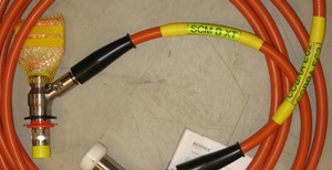
Jumpers require identification of the jumper service, and the connecting interface. This helps with planning installation so that the jumpers can be laid out on the deployment frame for deployment and hook up. Such identification markings need to be located at least at each end of the jumper and at least once along the length.
23.3 Marking Methods
There are different methods that are used to add marking on subsea equipment like painting (stencilled marking), using stickers, and letter cutting on frame).
Painting is an easy method of identification and most of the time marking is painted in black.
The orange colour is used for recoverable modules and for ROV interfaces (API 17H bucket of valve actuator, ROV handles, ROV grab bars, handle for quarter turn valve operation, EFL/HFL/OFL connector, etc.). Minimum requirements in terms of size and colour for subsea structures are defined into Annex B ‘Colours and marking’ of ISO 13628-1.
These labels will be covered in marine growth in time, which will need to be brushed or jetted away when returning to the site for intervention.
There are also subsea markers available with anti-foul properties to inhibit marine growth, although the use of these is sometimes restricted for environmental reasons.
Jumper hoses and cables are marked with cable markers with black lettering on a yellow background. These are fixed to the jumper at each end with cable ties. To ensure that these markers do not detach due to snagging during handling a clear heat shrink sleeve is applied over the marker. They need to be large enough to ensure clear visibility.