18 Subsea Control Module Mounting Base (SCMMB)
18.1 General
The SCMMB is the interface between the Subsea Control Module (SCM) and the Xmas tree or manifold/template functions that it is controlling and the remote sensors.
18.2 Construction
The SCMMB may be a welded construction, fabricated from carbon steel and painted to provide corrosion protection, or maybe of the form of a plate which is assembled to the Xtree base. It is bolted and earth bonded to the protective structure.
18.3 Interface with SCM
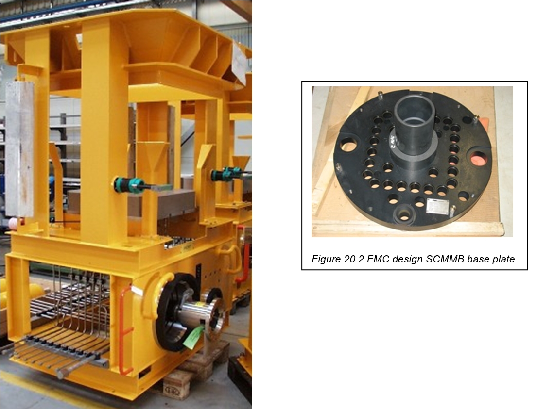
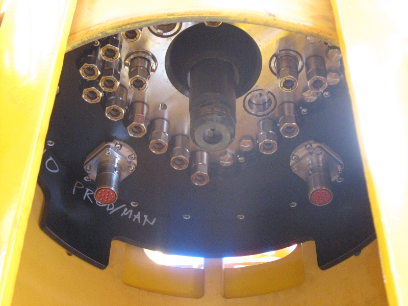
The mating interface with the SCM is a horizontal stainless steel plate with the connections vertically upwards.
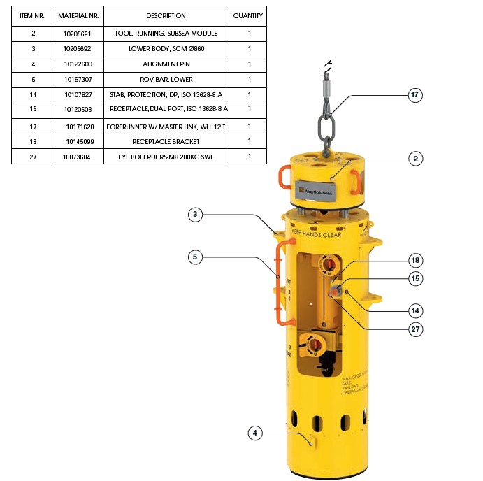
For an ROV installation, there are vertical tubes with an ROV locking interface as per API 17H. The ROV eploys and latches the SCM into place.
A vertical face on the side of the SCMMB is used for incoming connection interfaces with the incoming electrical connectors for the power and signal cables, and incoming LP and HP hydraulic supplies.
18.4 Workover System Interface
Depending on system design, the vertical face of the SCMMB may also be used as an interface with the Workover control system via a stab-plate connection. Removal of a crossover plate disconnects the hydraulic functions from the SCM, and connection of the work-over stab plate enables connection directly to the Xmas tree production valves, and also connection of the additional work-over valve and test functions.
18.5 Interface with Tree Valves & Sensors
The permanent connections from the SCMMB to the Xmas tree are by connections on the underside of the stainless steel interface plate. The connections from the hydraulic couplings are by rigid tubing to the Xmas tree valve actuator functions.
The electrical connections are by cable assemblies pre-made to electrical connectors at both ends and tested, which are assembled to the mounting base through upward looking electrical connectors flange mounted which are fixed to the mounting base horizontal stainless steel mounting plate.
18.6 Docking Alignment
The SCMMB will have coarse alignment and fine alignment for locating the SCM. For fine location by guide pin or orientation key, the SCM will not land if the orientation is incorrect. For self-aligning SCMs, a central helix or guide slot will automatically rotate the SCM to the correct orientation before it is able to land.
Due to the number of electrical and hydraulic connectors in the mounting plate, there has to be an allowance for installation tolerances during make up. Therefore all of the connectors are secured through the mounting plate and not directly secured to it, allowing movement as the SCM docks and locates in position. Care must be taken to ensure electrical continuity for corrosion protection reasons.
18.7 Latching mechanism
The final latching of the SCM to the mounting base is done in several ways depending on the design. With some designs the central mandrel in the SCM is pushed down operating an over centre mechanism which then exerts an upward force onto the underside of the SCMMB interface plate, release of the SCM is the opposite by pulling vertically upwards on the mandrel. Other designs utilise a central screw which extends from the top of the SCM to the base which engages latching segments to the central housing via hydraulic pressure.