2 Control System Types
There are several types of Subsea control systems. The most commonly used in today’s industry is the Electro-Hydraulic Multiplexed design. However as oil exploration has reached deeper waters and more remote destinations, the requirement for all electric systems has increased.
This section describes the different systems which are in use in the industry today; we shall look first at the most basic and simplest systems to understand their functionality and then move on to the more modern systems available in today’s industry.
There are five basic designs:
1961 – 1969: Direct Hydraulic
1971 – 1985: Piloted Hydraulic
1985 -> now: Electro-Hydraulic and Electro-Hydraulic Multiplexed
2008 -> now: All electric
2.1 Direct Hydraulic
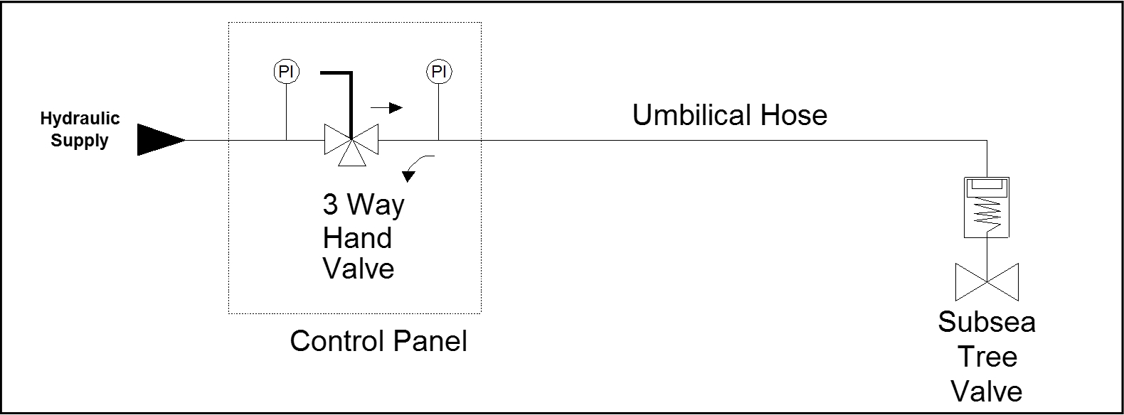
A direct hydraulic system is the simplest type of subsea control system. The basic component for the control circuit for a direct hydraulic actuation of a subsea valve is a three-way hand-valve mounted on a topside panel.
The valve inlet is connected to the hydraulic supply. The return is connected to the hydraulic reservoir, and the outlet connects to a hose in the control umbilical. The hose acts as a conduit that directs the hydraulic fluid to the subsea actuator. A pressure gauge on the topside panel at the three-way valve outlet gives an indication that the hand valve has been operated and hydraulic pressure is being supplied to the umbilical.
Main disadvantage is the requirement for a dedicated line in the umbilical for each subsea actuated valve which is not practical for multiple well fields. There are two other main limitations of this system, firstly response time and hence Offset Distance, and secondly lack of data for well monitoring or diagnostics.
When the three-way valve is actuated, hydraulic fluid from the HPU will flow through the valve into the hose in the umbilical. The hose is full of hydraulic fluid at atmospheric pressure. To open the subsea valve it is necessary to fully pressurise the thermoplastic hose over its entire length which will expand by a nominal 10%, and to flow through the hose the total volume of the valve actuator.
Opening the valve requires sufficient force to overcome the valve friction, the pressure in the valve bore, and to compress the return spring. Once the valve is open, it will remain open with very little hydraulic force.
The hose expansion can be minimised by decreasing its bore size. However there is a trade-off here in that the hose still has to flow the volume of the subsea actuator. With a small bore hose and a long offset, the internal friction in the hose makes flowing of hydraulic fluid very difficult to do, so larger bore hoses are necessary.
As the Offset Distance increases, the valve response time increases. The acceptable response time depends on several factors:
The energy of the well and hence its flow through the closing valve, and
The position of any safety valves downstream of the closing valve.
An acceptable response time must be determined by hazard (HAZOP) and safety analysis.
As an indication of the distances that can be controlled by direct hydraulic control using thermo-plastic hose, 4 km is probably the furthest that should be considered.
For deep-water applications, the umbilical length from the surface to the seabed has to be included into the 4 km nominal length and therefore limitations of direct hydraulic systems become apparent.
The expansion characteristics and the external crushing caused by the static head of seawater can be eliminated by using steel tube in the umbilical. There is one field in the Gulf of Mexico where an 11 km offset has been achieved using a steel tube umbilical in a direct-hydraulic system.
The closure of a subsea valve is the reverse of opening. By operating the three way valve into the closed position, the umbilical core vents to atmospheric pressure in the hydraulic reservoir. The volume of the actuator and the expansion of the hose core have to be returned to the hydraulic reservoir in order for the valve to return to the closed position using the force of the return spring.
In order to achieve the simplicity of the direct hydraulic system, there is one hose conduit for each hydraulic function, and there are no cables in the umbilical for data monitoring.
It is possible to include twisted and screened signal pairs into an umbilical to access data from transducers using 4-20mA loops. This capability is dependent on the power drivers for the loops and the size of the conductors, and the Offset Distance. There needs to be a twisted and screened signal pair for each transducer.
Another consideration in deep-water applications is that gate valve actuators may require larger springs to compensate for the pressure caused by the static head of seawater. The size of the spring usually requires larger spring cartridge housing, and hence the valve actuator volume also increases, having detrimental effects on valve opening and closure response times.
Control fluid pressures may be increased allowing the use of smaller actuators. Also, balanced stem actuators may be employed to reduce the resistance to motion from the hydrostatic pressure.
2.2 Piloted Hydraulic
The piloted hydraulic system is a variation to the direct hydraulic system, with slightly more complexity to overcome the limitations of the direct hydraulic system. Similar disadvantage to direct hydraulic regarding need for large number of subsea valves.
The piloted system requires two hoses in order to function, and a piloted control valve subsea adjacent to the valve actuator. The objective of the system is that instead of the compromise choice of umbilical hose size for optimum performance using a direct hydraulic system, the piloted system uses a small bore hose for the pilot line and a larger bore hose for the supply line.

The objective is that the (preferably) large bore hose that is required to flow the volume of the actuator is continually pressurised from the hydraulic power unit. Therefore on valve actuation there is no delay whilst this hose is pressurised.
The small pilot hose is operated using a three way panel mounted valve supplied from the hydraulic power unit in a similar manner to the direct hydraulic system. The difference between the systems is that although the hose will expand under pressurisation, the smaller hose requires less expansion. Secondly, the hydraulic pilot volume to actuate the pilot valve is very small and hence there is very little volume flow required to energise the pilot valve and to open the subsea valve. The result is that the valve actuation time is improved.
The valve closure is the reverse procedure. When the three way valve in the control panel is moved into the closed position, the pilot line starts to depressurise into the hydraulic reservoir. The volume in the pilot hose is small, and the pilot return spring can be designed to snap action closed at a higher pressure than it is possible from the valve actuator in the direct hydraulic system.
The snap action closed of the pilot valve connects the subsea valve actuator to sea, and the return closed action of the subsea valve spring pushes the actuator volume to sea. As the subsea valve actuator volume does not have to flow along the length of the umbilical, valve closure time is also significantly reduced.
For multiple subsea valve applications such as on a Xmas tree, there is a requirement for a pilot hose for each valve, but the larger supply hose can be used as a common supply feeder to all of the pilot functions to all reducing umbilical size and cost.
2.3 Electro-Hydraulic
The electro-hydraulic principle is similar to the piloted hydraulic system. The difference is that the pilot valve adjacent to the Xmas tree valve is replaced by a solenoid valve (also called Directional Control Valve DCV).
The following figure shows the electro-hydraulic principle with an electrical switch in the Topsides panel being made to energise the solenoid coil, which then energises the valve shuttle and connects the hydraulic supply through the umbilical to the valve actuator to open the valve. Closing is the reverse, by de-energising the solenoid the shuttle moves to the closed position by spring pressure and the supply is blocked and the actuator is connected to the vent for closure.
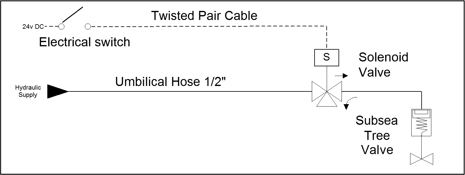
With the system as shown above, a cable pair has been introduced into the umbilical for one function only. Therefore for each additional function using this system another cable would be required in the umbilical. A standard solenoid has to be continually energised to stay open and to hold the subsea valve open. The solenoids may have a low power requirement, but voltage drops in the cable over long Offset Distances dictates a reasonable size cable conductor will be required.
Also if further signal pairs are added to the configuration, the umbilical will grow in diameter adding to the cost and also making it more difficult to handle during manufacture and during load out and installation.
2.4 Electro-Hydraulic Multiplexed
A typical EH umbilical will normally consist of dual LP, dual HP, chemical lines, and two or more pairs of cables (or quads) depending on the design. Sizes and quantities depend on the field requirements and the overall dimensional limitations of the umbilical diameter.
Depending on system design, separate cables can be used for power and signal distribution or some systems combine both power and communication transmission on the same pair.
This type of system utilises modems topside and subsea to enable communications.
The subsea modem is housed in the Subsea Electronics Module (SEM).
The SEM is a fabricated vessel able to withstand external pressure and that acts as one atmosphere sealed nitrogen purged housing.
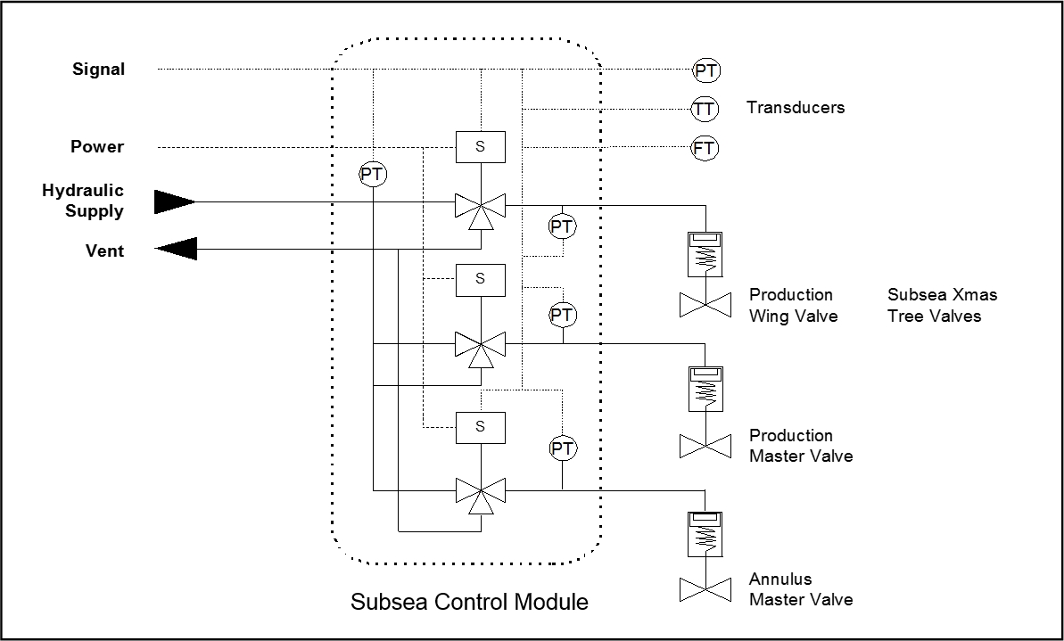
Inside the SEM are the power supplies, step down transformers, AC to DC converters, modems, electronics boards to interface with internal and hydraulic remote sensors for hydraulic circuit (PT, Flowmeter, TT, etc.), driver boards for the solenoid valves, and some signal processing.
The added complexity of this system provides a great deal of flexibility and allows for monitoring of some of the circuitry to provide a health check on the system by providing data for housekeeping. As most modern systems contain control boards, there is scope for 'intelligent' handling of data and/or response to events such as high/low pressure alarms.
The step-down transformer (in some case located in other recoverable electronic module called Subsea Router Module SRM) within the SEM allows the power within the umbilical to be transmitted at the optimum voltage for efficiency, which can then be stepped down within the SEM transformer to the voltages required for powering the electronics, internal and external sensors (downhole, XT or Manifold mounted) and energising the solenoid valve coils.
Often, especially in deepwater developments, dual-redundant SEMs are specified.
The solenoid valves are packaged into an housing along with the SEMs and integrated into what is called the Subsea Control Module (SCM).
In order to communicate with the subsea control module, a modem is required topsides at the surface end of the communication pair. The interface between the Operator and the ESD system, etc. is by a computer system commonly known as the Master Control Station (MCS) or Subsea Control Unit (SCU) (described further in Chapter 7, Master Control Station (MCS)).
The subsea power is provided topside via several Electrical Power Units (EPU: described in chapter Chapter 8, Electrical Power Unit (EPU)), and the hydraulic supply is from one Hydraulic Power Unit (HPU; see chapter Chapter 10, Hydraulic Power Unit (HPU)), the same as for the other control system types.
For deep-water applications where flow assurance and reservoir management are required, the electro-hydraulic control system provides benefits that the two previous systems cannot.
2.5 All Electric Control System
The world’s first all-electric system, was installed in 2006 in the Dutch Sector (North Sea) for TOTAL K5F development and consists in an all-electric, trees (2 all-electric trees provided by OneSubsea) and control system.
In 2012, second generation of DC all electric system is developed by OneSubsea and in 2016 a first electric Surface Controlled Subsea Safety Valve (SCSSV) is installed on K5F3 development.
All electric systems represent a breakthrough in technology and propose a better solution to the risks of subsea production, and reliability for offshore operators.
Majority of SPS Contractors are developing all electric control systems which are a key technology for new subsea processing technologies, long-tie back, ultra-deepwater application and long-term vision of the subsea factory.
The all-electric system is powered by direct current and it potentially offers a dramatic improvement in terms of reliability, availability and maintainability since the system has no batteries, hydraulics or accumulators (topside or subsea).
The main advantage of an all-electric system is the ability to accommodate longer step out distances (›100 miles) with significantly improved response times compared with conventional systems and at lower price (CAPEX and OPEX)
Without the use of hydraulic systems and the inherent response time lag through the umbilical, communication, feedback and monitoring of subsea equipment should be very much improved.
There are also environmental, health and safety advantages when compared with conventional hydraulic systems, since there are no risks from hydraulic leaks and the problems associated with fluid storage and discharge to sea are eliminated. Another benefit of all electric system over hydraulic system is also to avoid the issue of internal/external leaks and also risk of gas migration into LP or HP system where hydrates can form (several examples on B17 and Congo regarding hydrates formation in HP lines or at the SCM venting point).