21 Multi Phase Flow Meters
21.1 Introduction
As technology has advanced, the use of Multi Phase Flow Meters (MPFM) has become more common in the industry. The main purpose of the subsea MPFM is to provide Field Operations with an accurate, continuous measurement of Oil and Gas when flowing in a ‘mixed’ state i.e. before separation.
21.2 General
The Subsea MPFM is a complex device which is designed for accurate and continuous measurements of multiphase composition and flow-rates. The MPFM measures flow-rates of oil, water and gas coming from wells or flowing in pipelines and can normally be installed at a Xmas Tree, on a jumper, or at a Manifold.
21.3 Materials
The main body of the MPFM will be of corrosion resistant material such as Duplex stainless steel, exact requirements will be project specific and will need to be compatible with flow line materials and comply with industry standards.
The internals (process fluid exposed) will be typically of titanium, hastaloy and inconel. Sea water exposed will be of 316SS L and titanium or super duplex, depending on application.
21.4 Construction
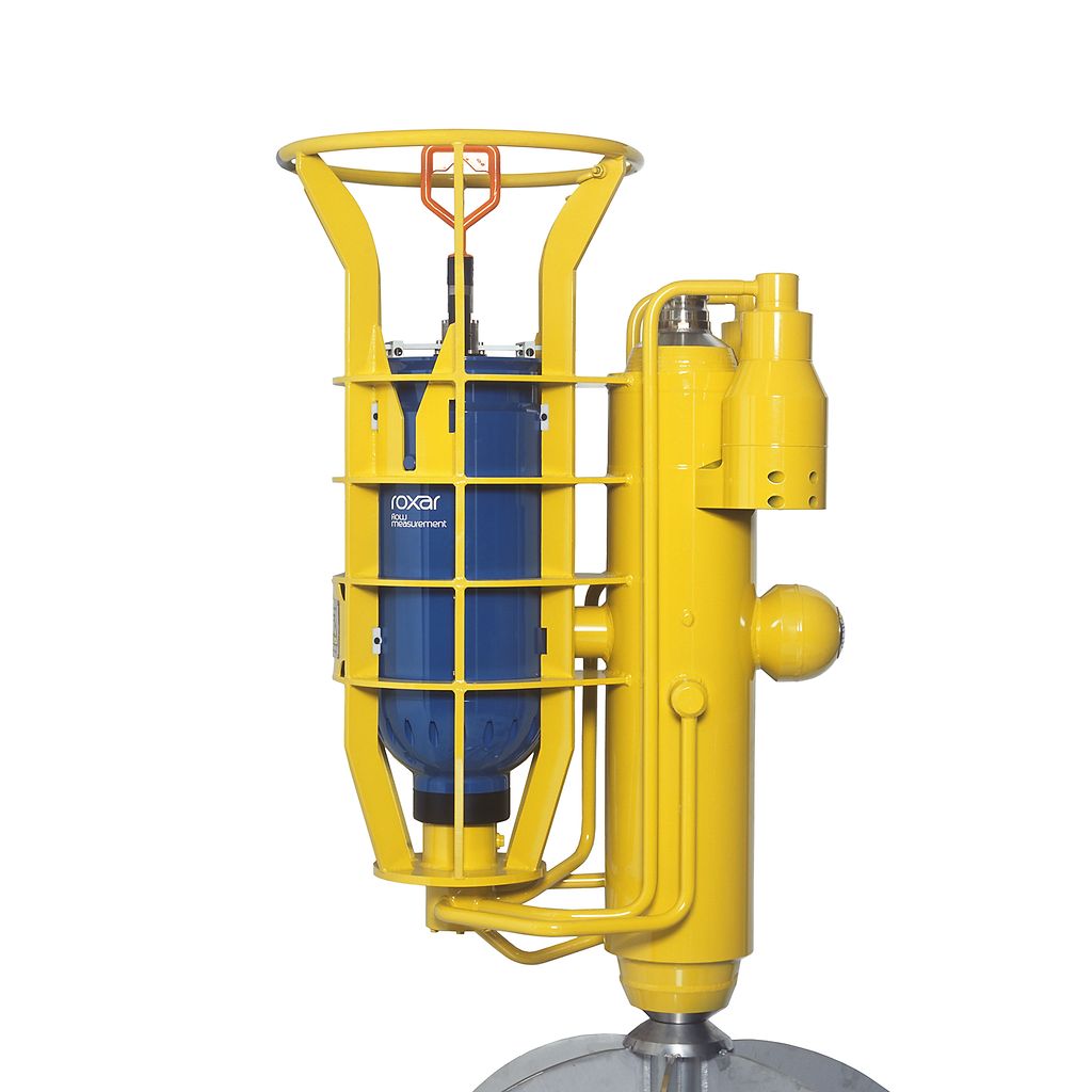
The main body of the meter will be welded to the production well jumper or XT piping or Manifold piping, whilst the electronic canister will be normally be separately retrievable by use of a ROV with manipulator arm for maintenance etc.
Figure 21.1 - Subsea multiphase flowmeter with recoverable electronic canister (in blue) (Emerson ROXAR MPFM)
21.5 Functionality
The multiphase meter carries out composition and velocity measurements on a continuous basis. Data is transmitted to the MPFM processing station, provided by SPS supplier, which will be located topside. This data is sent from the MPFM, via the SCM and transmitted to the MCS and operator station.
Typical information will be as follows
Date and time
well involved, manifold and MPFM identifications
Real time data:
Pressure and temperature
Total liquid, anhydrous oil, water, gas flow rates at actual conditions:
volume and mass
Oil, water and gas volumetric flow rates at standard conditions
Water cut and GVF fractions
Oil, gas and water density at line conditions
Gas and liquid velocity
Mixture density
Accumulated values (between sequential polling periods)
Total liquid, anhydrous oil, water and gas quantities in volume at standard
conditions
Total liquid, anhydrous oil, water and gas quantities in mass
Average values (between sequential polling periods)
Pressure and temperature
Density
21.6 Accuracy
Typically the accuracy requirement would be:
• Liquid flowrate ±10% of reading
• Gas flowrate ±10% of reading
• Oil flowrate: ±10% of reading
• Water in liquid ratio ±2% absolute for GVF < 90% (Gas Volume Fraction)
Sensitivity of the water cut measurement may be sufficient to detect water breakthrough
less than 1% WLR (Water in Liquid Ratio)
The MPFM will be expected to have a typical design life of 20 years and shall be able to monitor the production fluid evolution all along the field life without the need to be refurbished.
Tests can be carried out to verify the accuracy of the meter against single phase measurement instruments. By simultaneously testing the MPFM and single phase meters with the same process medium, a direct comparison can be achieved and recorded. However the test equipment involved is specialised and there are very few premises available which can accommodate this equipment.
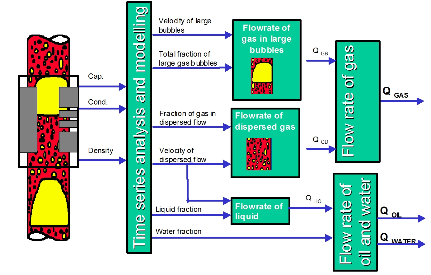
21.7 Methods of Measurement
The mixed state of gas, oil, and water is measured by various methods, these comprise of capacitance measurement, inductive measurement and gamma radiation measurement.
21.7.1 Gamma densitometer
The purpose of the gamma densitometer of the MPFM is to measure the total density of the mixture flowing in the pipe. Because of the significant difference in the densities of the liquid and gas of an oil/gas/water mixture, the rate of the absorption gives an accurate measurement of the liquid and gas fractions of the mixture.
The absorption of gamma radiation in a medium is a function of the mean density along the path of the gamma particle beam. This is a well-known principle used for many other applications.
21.7.2 Capacitance sensor
The purpose of the capacitance sensor is to measure the fraction of oil, water and gas of a flow going through the meter. This is accomplished this by measuring the permittivity of the oil/gas/water mixture. Permittivity is an electrical property which is different for each of the three components in an oil/gas/water mixture, and the permittivity of the mixture is therefore a measure of the fractions of the different components. Permittivity is also sometimes called the dielectric constant.
This capacitance measurement works as long as the flow is oil continuous, i.e. as long as water is dispersed in the oil and does not form a continuous path of water between the electrodes. This would short-circuit the electrodes, and the unit would not be able perform correct measurements. Normally, the flow is oil continuous as long as the water cut is below approximately 60 – 70% of water. For higher water cuts the flow will normally become water continuous. For these situations the inductance sensor is used.
21.7.3 Inductance sensor
The capacitance principle is not suitable in water-continuous flow. For this reason the mixture conductivity of the oil/water/gas flow is measured by a conductance sensor during water continuous liquid. It uses magnetic coils to induce a current through the liquid inside the sensor (thereof the name inductive sensor)
This information is then fed to the flow computer for calculation of oil, water and gas fractions.