
6 System Outline
6.1 General
A subsea control system can be divided into three main sections:
The permanently installed topsides equipment
The umbilical and its terminations
The permanently installed subsea equipment
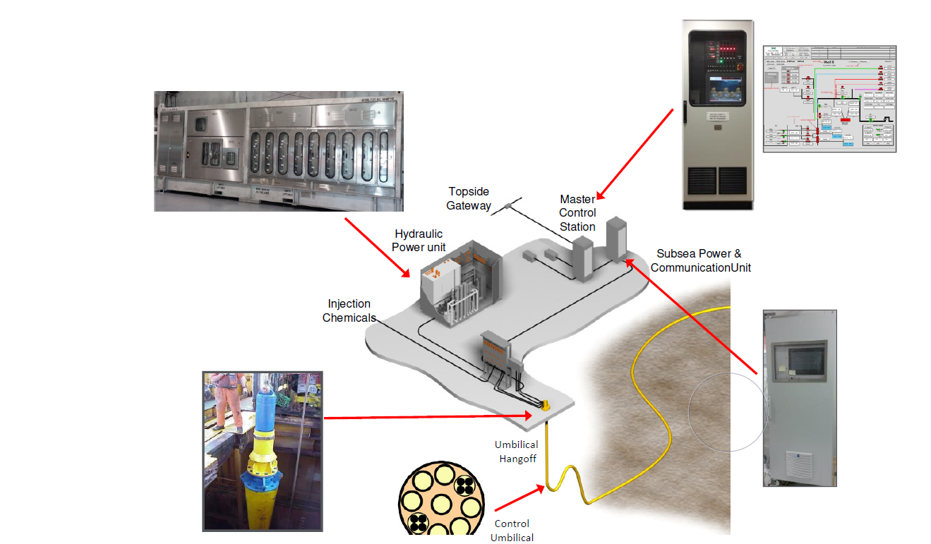
6.2 Topsides
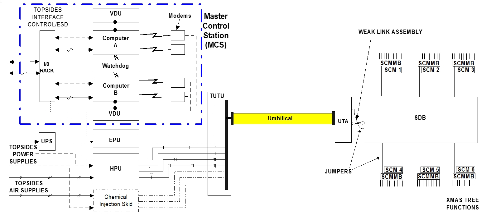
The topsides equipment has a Hydraulic Power Unit (HPU) which is required for Hydraulic or Electro-Hydraulic systems. The electro-hydraulic control system also has a Master Control Station (MCS or SCU), and an Electrical Power Unit (EPU or SPCU).
6.3 Umbilical
The control umbilical interfaces with the topsides umbilical termination via the Topsides Umbilical Termination Unit (TUTU) and the Subsea Umbilical Termination Unit (SUTU) at the subsea termination.
The various types of Umbilical required are discussed in the Deepwater Field Development Reference Book – Umbilicals ([68]).
6.4 Subsea
The Subsea Distribution Unit (SDU) can also be directly attached to the umbilical, but is often a separate unit especially where an umbilical weak link is required.
The SDU distributes the hydraulic supplies and electrical power and signals to each of the locations where there is a requirement for a subsea control module (SCM) (like on XT or Manifold) or hydraulic actuated valves or monitoring sensors (like on ILT/FLET or SSIV)
Electrical and Hydraulic Jumpers connect the SUTU to the SDU (possibly via a weak-link), and the SDU to the Subsea Control Module. These can be diver or ROV installable.
The Subsea Control Module Mounting Base (SCMMB), which is usually mounted onto the Xmas tree of the subsea well, is the interface with the subsea control module. The SCMMB connects the outputs from the SDU into the SCM, and the Xmas tree hydraulic functions and monitoring sensors into the SCM.
For the majority of modern systems, which will be diver less for deepwater applications, the SCMMB will have upward facing hydraulic and electrical connections to mate with the downward connection of the SCM during installation. In a diver-assisted system, the SCMMB may merely act as a 'parking' position for diver-installed stab plates and connectors.
The Xmas tree valve actuators are usually connected to the SCMMB using stainless steel tubing. The sensors are usually mounted to the Xmas tree piping via a standard (API or other) flange and secured by stud bolts and nuts. The sensors are connected to the SCMMB by jumper electrical cables.
Sensors may, however, be flush-mounted to limit hydrate blockage, in which case they cannot be mounted using double block and bleed valves; they therefore cannot be removed without depressurisation of the pipe work on which they are mounted, and this will have important consequences for repair/replacement, such as the need to stop production to change a faulty sensor.
Excessive demand for hydraulic fluid whilst opening Xmas tree valves in a sequence can momentarily reduce the local system pressure and hence cause valves that are already open to fail closed due to the drop in hydraulic pressure. This possible scenario will be evaluated when performing the hydraulic analysis, if it is considered possible; a Subsea Accumulator module (SAM) will be included in the system to prevent this occurrence. The SAM can be constructed as part of the SCM, or attached to the tree or positioned at the manifold, depending on design preferences. It can be also designed as a single retrievable unit (like Subsea Accumulator Module on Laggan Tormore Template Manifold)
![[Tip]](tip.png) | Tip Click these links below for access to 3D resources: |


