
8 Electrical Power Unit (EPU)
8.1 General
Any electro-hydraulic Multiplexed subsea control system requires a topsides unit to control and provide the necessary power to the subsea equipment.
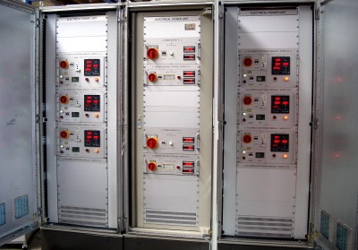
The Electric Power Unit (EPU) is the generic name usually given to the equipment that performs this function. It will usually comprise of one or more racks of equipment, located in an Equipment Room.
The EPU can sometimes be incorporated within the MCS cabinets (depending on system size).
8.1.1 System Operation
A subsea system will usually require power in a form different to that normally available on the Platform/FPSO. This is because of several reasons:
The early systems used ‘inductive couplers’ which require high(er) frequency power for efficient power transfer, typically 400Hz (being typically based on aviation technology).
Even after conductive connectors began to be more widely used, Suppliers still kept their existing designs of power supplies.
Where a normal 50/60Hz supply is required, the supply voltage may require stepping-up to a higher level in order to supply the distant subsea field, to reduce the I2R losses in the umbilical cable.
Some supplier’s systems use direct current (DC) for power transmission, again at high voltages to reduce cable losses.
Most subsea systems require dual-channel (Channel A and Channel B) power for redundancy reasons.
More frequently modern systems communicate subsea by superimposing signals onto the power supply (comms on power)
In addition to conditioning the available topsides power into the form required for transmission subsea, certain other control and monitoring is required, such as:
Overall on/off control of the power to the EPU and to the subsea system itself.
Individual control of each power channel.
Protection for over-current and over-voltage.
Monitoring of the supply voltage, current and frequency.
Monitoring of the quality of the insulation of the subsea electrical lines.
Replication of the measured parameters back to the Master Control Station (MCS).
Adjustment of the output voltages when more Subsea Control Modules (SCM) are added to the system.
A degree of regulation (stabilising, smoothing) of the incoming supply may be required.
All of these requirements usually mean that an EPU becomes a self-contained unit, and is of an appreciable size, weight and complexity.
It should be noted that, regardless of the type of power required by the subsea system, a reliable supply is always required. This means that the system should ideally be supplied from the Topsides Uninterruptible Power Supply (UPS) system. In the absence of this, or where the existing supply is inadequate, a separate UPS is often required. This is described separately in section Chapter 9, Un-Interruptible Power Supply (UPS); as it does not usually form part of the EPU, due to its specialised nature and size.
8.1.2 Physical Description
Modularisation of the unit by the Supplier may mean that one or more EPUs are required to power a large field, and the racking system usually contains space for such expansion. Sometimes the EPU requirements are small enough to allow the EPU to be mounted in the same Rack as the MCS. In general, an EPU will be designed to fit in a standard 19" rack and be protected against dust and water ingress to at least IP55.
An EPU will often contain large and heavy transformers, so although the control and monitoring circuitry is relatively small, an EPU is usually fairly large and heavy.
The EPU will often generate an appreciable amount of heat, and this should be taken into account when positioning the unit and/or designing the local HVAC system.
The racking system will be equipped with Certified lifting pad-eyes, gland plates (provided on the top or bottom of the unit) to accept glanded incoming and outgoing cables and "Klippon" SAK-type connectors, or similar, as terminations for all incoming and outgoing cabling.
The enclosure should have two non-ferrous earth studs for bonding to the earth system. All enclosure metal parts should be securely connected back to the earth studs by bonding straps. An earth-bonding strap is required. The enclosure shall be suitably coated and painted in accordance with a suitable specification.
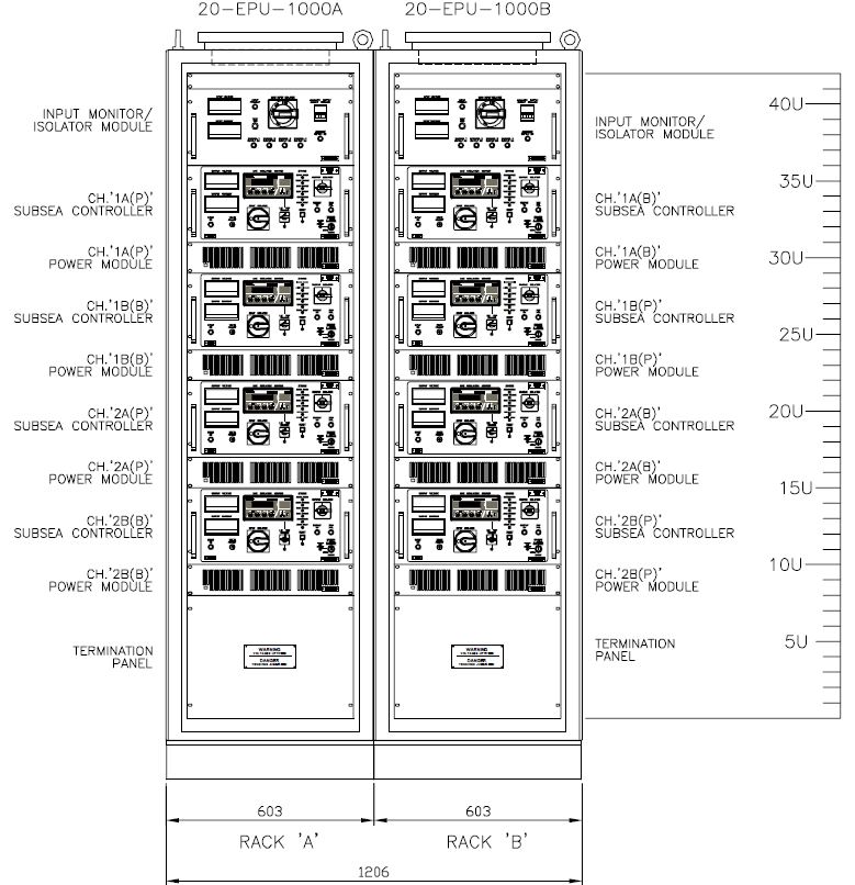
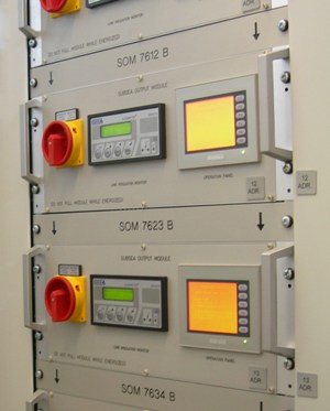
On Moho Nord, each EPU cabinet is composed of one rack, composed of:
one input monitor module
several subsea controllers
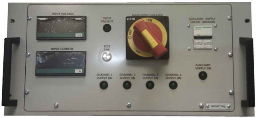
The input monitor module provides input voltage & current monitoring and isolation from UPS input supply.
Each subsea controller provides one output channel to subsea and includes control, monitoring and protection to the output.
8.1.3 Power System Specification
In order to specify the EPU requirements, each subsea system must be analysed for its current and future power requirements.
The power distribution system can be quite complex, particularly for 'multi-drop' systems, i.e. those having many Subsea Control Modules operating from a single (dual-channel) umbilical and with, in some cases, further umbilicals operating in a daisy-chain to another field or collection of Subsea Control Modules. The system may require subsea Transformers, usually located in the Subsea Distribution Units (SDU; see chapter Chapter 15, Subsea Distribution Unit (SDU)) to transform the voltage back down again to a level suitable for the SCMs or for local distribution on a template. An SCM will contain its own Power Supply system to obtain the (typically) 24 volts to operate sensors and solenoids, and 5 or 12-volt logic circuits.
The system must be designed to accommodate the various levels of power required by the system in all its operating modes. An SCM in its normal operating (scanning) mode may only consume some tens of watts, but when a solenoid is activated this will rise by about the same amount. Some system designs incorporate 'held-on' solenoids in the SCM, this increases total power requirements, as does each additional external sensor. Systems employing major power-consumers such as down-hole pumps obviously have very particular requirements. The EPU is usually required to be able to adjust the subsea supply voltage to cater for the addition or removal of SCM’s.
The system must also accommodate any expected fluctuations from the FPSO/Platform Supply; therefore the subsea system is usually fed from the Topsides UPS, or has its own. Transient protection and phase-angle correction may be required.
Any over-current protection devices in the system must be co-ordinated, to ensure that only the fuses/devices for a faulty SCM operate and do not trip the main supply for the rest of the system.
8.2 Components
8.2.1 General
A typical EPU comprises the following components:
Main input circuit breaker.
Power Transformer & Isolation.
Output circuit breakers and current limiters.
Line Insulation Monitor.
Controls and displays
8.2.2 Main Circuit Breaker
The incoming Topsides supply is routed via a main input circuit breaker, which should be lockable for use during topsides or subsea maintenance. The isolator is often interlocked with the EPU access door in order to ensure supply is isolated before the door can be opened. Warning labels should advise the consequences of opening the door. The contact breakers may be equipped with over-current and over/under-voltage trips to protect the unit.
8.2.3 Power Transformer/Power Stage & Isolation
An isolation transformer converts the incoming supply voltage to the level required for subsea transmission. If the incoming supply is of the wrong frequency or requires other treatment, then a power conversion stage may be employed, such as a switched-mode regulator or other power-supply technology. With these devices, care must be taken to ensure unwanted harmonics are not transmitted subsea (could interfere with the communication channel via cross-talk) or are reflected back to the Topsides supply.
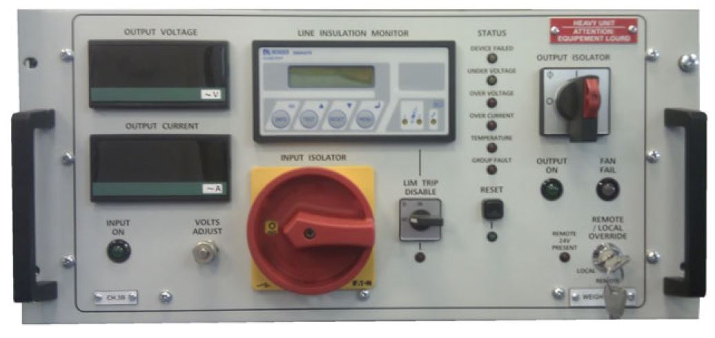
8.2.4 Output Circuit Breakers & Current Limiters
Outputs are usually fed via circuit breakers with thermal and magnetic trips and/or fuses rated according to the subsea control system requirements. The circuit breakers should be lockable in the off position, for maintenance purposes. The circuit breakers are often provided with auxiliary contacts for remote indication to the MCS.
In some system designs where subsea held-on solenoids form part of the ESD system, a relay connected to an incoming ESD signal may trip the output supplies, in which case a manual 'reset' button is included to avoid un-wanted restoration of power after the ESD condition is removed.
8.2.5 Line Insulation Monitor
The insulation between line and earth on both power outputs should be monitored by a Line Insulation Monitor (LIM). The LIM should have two levels of operation:
Level 1 - At a pre-set level should indicate only "Pre-trip warning".
Level 2 - At a pre-set level should trip the output circuit.
The LIM should be rated and / or compensated for use with subsea umbilicals of the construction and length required for the application.
8.2.6 Controls & Displays
For each EPU, the dual output (Channel A and Channel B) supplies should have the following indicators mounted on the front panel:
Voltmeter
Ammeter
Frequency meter.
Line insulation fault lamp.
Output-on lamp.
Output-tripped lamp.
Line insulation resistance.
8.3 Testing
The EPU should be subjected to a witnessed Factory Acceptance Test (FAT) procedure. The acceptance testing should include, but not be limited to:
Heat soak tests / Burn in period.
Visual checks on workmanship, cable marking etc.
Insulation testing cores to ground and each other.
Continuity testing.
Earth continuity tests.
Circuit breaker tests.
Line Insulation monitoring tests (particularly as regards usage with subsea umbilicals and long-term Testing).
Operational tests over the full range of input / output voltage, frequency and loads, and start-up surges.
8.4 Maintainability
EPU’s are usually modular in design, allowing for access to all components for maintenance or repair, and for isolation of individual power supplies.
Interlocks are often implemented on the access doors, such that internal power is switched off when the doors are opened (over-rides are often available should it be necessary to maintain subsea power).


