10 Hydraulic Power Unit (HPU)
10.1 Introduction
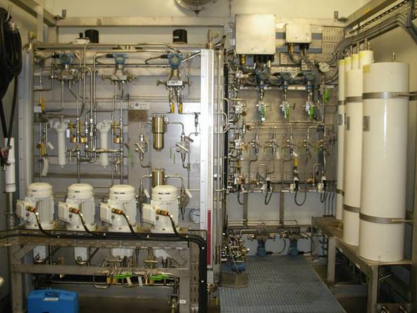
The Hydraulic Power Unit (HPU) is a skid mounted unit designed to supply water based bio-degradable or mineral oil hydraulic fluid to control the subsea valves. Normally the HPU will be located in a Zone 2 hazardous area on board the FPSO or platform and has to be designed to this criterion.
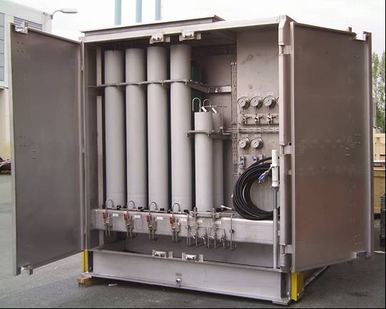
A typical HPU has a supply reservoir and return reservoir, LP and HP pumps and a circulation pump for filling and flushing.
The reservoirs, tubing, and wetted parts of all components including hydraulic pumps, hand valves and control valves are normally manufactured from 316L stainless steel to prevent corrosion and contamination in the hydraulic system. However TOTAL project specifications have shown a preference for the use of 904L stainless steel for hydraulic tubing.
The two hydraulic system pressures are low pressure (LP) for the Xmas tree valves and high pressure (HP) for the sub-surface safety valve (SCSSV). Each system will normally contain a duty and redundant standby pump system for back up and maintenance purposes. LP pumps are normally electrically driven, HP pumps electric or air driven. The redundant pumps are set up in a lead/lag configuration redundancy, so that the redundant pump will activate at a predefined pressure set point should the lead pump have failed or been unable to maintain sufficient system pressure.
A bank of accumulator bottles with an internal bladder or piston and Nitrogen pre-charged stores the energy from the pump discharge to prevent frequent on/off cycling of the pumps.
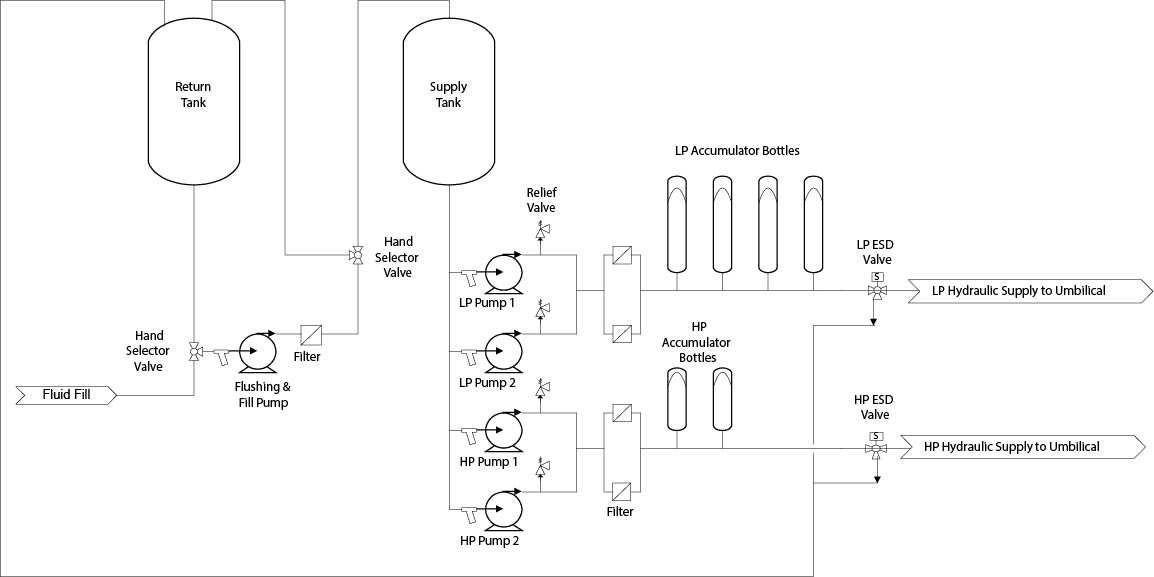
The pressure pumps are gravity fed from the supply reservoir. Each pump pressure system discharges through a dual filtration unit, charges a bank of accumulator bottles, and outlets the skid into the umbilical system. There are hand valves for manual isolation and solenoid valves (ESD) for safety shutdown of the umbilical system.
The system can be an “open loop” hydraulic system where fully biodegradable spent hydraulic fluid is dumped to sea, or a “closed loop” system where spent hydraulic fluid flows along the return line in the umbilical to the return reservoir. However in most modern deep water systems “open loop” systems are preferred, mainly due to cost implications.
The return reservoir has multiple service duties. It receives the return hydraulic fluid from the umbilical of a closed hydraulic system. It receives fluid from the manual or automatic vent of the skid or accumulators, from the system relief valves and ESD valves in the event of a shut down. It is also used for filling the system.
For closed systems with no leakage, there should be no requirement to refill the reservoir, but open systems will require topping up from time to time. The frequency of topping up is dependent on the frequency of operation of the subsea valves, valve actuator volume and the hydraulic losses in the system.
The final service of the return reservoir is for flushing and cleaning the hydraulic fluid to the required system cleanliness before transferring the control fluid to the supply reservoir.
A high flow multi-purpose circulation and transfer pump with filters is provided for flushing the fluid in the return reservoir and transferring of hydraulic fluid between reservoirs, or for flushing of the fluid in the supply reservoir, if necessary. Normally there is a separate air driven filling pump for filling from external sources, i.e. a barrel pump.
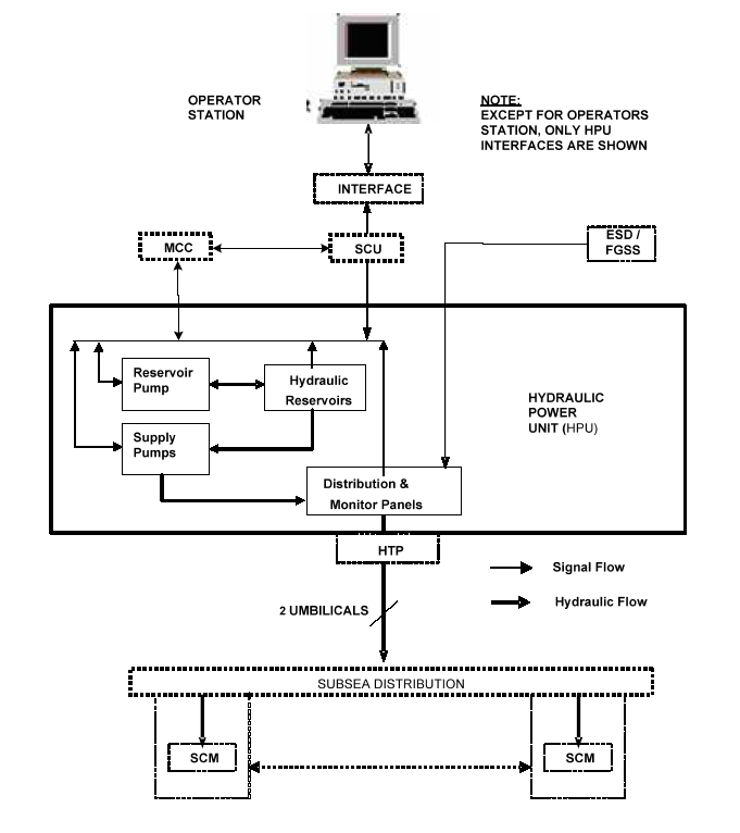
Control and monitoring of the HPU is automated from the MCS (SCU). Via the DCS the operator will be able to see the status of the main HPU components i.e. pump running, reservoir levels, filter clogged, etc. Some control parameters can be accessed and changed e.g. pump start/stop set points but this will be dependent on the security access level at the operator station.
Alternatively, depending on project requirements, the HPU can be designed to operate autonomously under the control of its dedicated programmable logic controller (PLC), which provides pump motor control, interlocks and interface with the MCS.
TOTAL projects have preferred using MCS control, therefore to avoid confusion; reference in this document will be to use this method of control.
The HPU has a local control panel for indication of hydraulic system pressures, hand/off/auto selectors for the pumps, and duty/standby selection for the pumps, and emergency stop controls normally for each pump. The panel will also have a common alarm lamp, and an audible alarm horn. The common alarm can also be provided at the Master Control Station or DCS.
10.3 Equipment Description
10.3.1 Supply Tank
The supply reservoir is fabricated from stainless steel. Its size is determined by hydraulic analysis depending on the number of umbilical volumes, manifolds, wells, valve actuator requirements during valve opening. The reservoir is vented to atmosphere, and is fitted with a micronic breather element and flame arrestor to prevent contamination of the fluid by airborne particles and risk should subsea gas permeate into the system.
The reservoir is fitted with an external level gauge for visible fluid level indication. The level gauge or reservoir will have transmitter level switches for high and low alarms, which can provide remote indication at the operator screen, and normally a contact switch for low-low level pump trip.
The tank has valve connections for pump supply, filling, draining, fluid sampling and flushing and filtration. There is also an inspection cover to allow maintenance access.
The supply reservoir shall receive clean fluid from the return reservoir only. The fluid shall be pumped from the return reservoir by the reservoir pump through a filter into the supply reservoir.
10.3.2 Return Tank
The return reservoir is fabricated from stainless steel. The size of the reservoir is determined by the hydraulic analysis taking into consideration the volume required to accommodate the HPU internal fluid bleed down from the accumulators and the return fluid from the umbilical and subsea installations, i.e. subsea accumulators, manifold and tree valve actuators, hoses and umbilicals during an ESD shutdown. As with the supply reservoir, the reservoir is vented to atmosphere and is fitted with a micronic breather element and flame arrestor to prevent contamination of the fluid by airborne particles and risk should subsea gas permeate into the system.
The reservoir is fitted with an external level gauge for visible fluid level indication. The level gauge or reservoir will have transmitter level switches for high and low alarms, which can provide remote indication at the operator screen, and normally a contact switch for low-low level pump trip.
The tank has valve connections for pump supply, filling, draining, fluid sampling and flushing and filtration. There is also an inspection cover to allow maintenance access.
A system drain is provided to remove excess fluid from the skid in case of overfill during ESD shutdown venting.
10.3.3 Low Pressure System
The LP hydraulic pressure pump system is normally electrically driven, (sometimes air driven on older systems). Each pump has a strainer on its suction in case of the unlikely event of debris becoming dislodged somewhere in the system. Each pump has flexible hoses on the supply and discharge to eliminate vibration stresses on the fixed tubing. Each pump has a hydraulic isolation valve on its supply and discharge for maintenance purposes.
The system is designed so that the pumps run on demand in a lead/lag configuration with one pump being the duty service and the second pump being the backup pump. Either pump can be configured as duty or standby. Each pump is protected by a relief valve set to 1.1 times the working pressure and a check valve to prevent back-flow from the accumulators through the pump.
The pump discharge is connected to a bank of nitrogen pre-charged accumulator bottles. The interface between the gas and the hydraulic oil can be either a synthetic rubber bladder or a piston with seal rings. The number of bottles, the volume, and the nitrogen pre-charge volume is determined by hydraulic analysis.
The accumulator discharge is based on the standard gas laws. The hydraulic analysis for the accumulator sizing must also consider the hydraulic pump discharge volume and the umbilical core sizing. The resistance to hydraulic flow over long Offset Distances even with smooth bore hose liners can be considerable.
The objective of the accumulator is to store the hydraulic energy provided by the pump(s) by compressing the nitrogen. When the pump reaches its high set point, it will stop (controlled from the MCS). As the umbilical hose pressure decays, the compressed nitrogen in the accumulator will expand and fluid will be forced out of the accumulators to recover the system pressure.
The pumps have a common discharge into the LP header. The LP discharge header is fitted with dual 3-micron absolute dual filtration system duty/standby to prevent contamination entering the umbilical.
Each filter contains a bypass in case of total blockage, which will allow the fluid to continue to flow, however in this case it will not be filtered. Both filters are fitted with isolation valves to allow replacement when clogged. Downstream of each filter is a valve for bleeding off fluid pressure during filter element changing, and for taking fluid samples for hydraulic cleanliness checking.
Each filter housing has a pop-up indicator warning of filter clogging and a differential pressure switch to provide a high differential pressure alarm either locally or remotely at MCS.
Pump control is via pressure transmitters fitted to the header, downstream of the pumps. Optimum configuration will use 3 transmitters to give a “2 out of 3” voting system (also mentioned as “2oo3” on P&ID and technical documentation) to the pumps in case of a transmitter failure. Feedback from the pressure transmitters is provided to the MCS (or HPU PLC if fitted) and pumps Start as system pressure decays to the Start set point and Stop as pressure decays to stop set point.
Each HP and LP pump set will have a Manual/Auto-duty control selection on the HPU Control Panel. In normal operations it will be set to Auto whereby start and stop are initiated from the MCS.
Panel mounted local pressure gauges will display the pump discharge pressures, and the accumulator header pressure. Pressure transducers will also provide a 4-20mA signal to enable these pressures to be displayed on the Master Control Station or DCS. These signals may also be used to provide low pressure alarms.
A flow meter will usually be incorporated into the line to detect flow from the header. This will provide a 4 -20 mA output to the MCS.
Each header output will be fitted with an ESD valve which can vent the supply header to the return reservoir on command from the DCS/MCS or in the event of total system failure i.e. loss of communication signal or power.
The ESD philosophy is determined from the system safety cause and effect charts and allows the system to close all xmas tree hydraulic operated valves and SCSSV to the Fail-Safe Close (FSC) position.
10.3.4 High Pressure System
The high-pressure pump system is similar to the LP system, however there are the following exceptions. The operating pressure is dictated by the force required to overcome the shut in well pressure and open the SCSSV.
The volume requirements are lower and the pump flow rates will be less. The hydraulic analysis will also dictate that the accumulator volumes will also be smaller. The operating and test pressure requirements for HP systems often border on the design operating limits of conventional seamless stainless steel tubing and compression fittings necessitating the use of high strength tube and high pressure fittings. Again, use of an electric pump can greatly speed the system re-pressurisation following an ESD and is normally preferred.
The accumulator(s) will be piston type to accommodate the higher system pressures.
The ESD valves will be fitted with a timer delay to allow the Xtree valves to close before the SCSSV.
10.3.5 Circulation/Transfer Pump System
The reliability of the subsea control system hydraulic components is highly dependent on the standard of cleanliness of the hydraulic fluid. To minimise contamination the fluid will be filtered to provide and maintain the fluid cleanliness at AS 4059 Class 6 B-F or better.
The circulation pump will be electrically driven, high flow, low pressure pump. By using a 3- way ball valve at the reservoir, it can be configured to circulate fluid in the return reservoir until the correct cleanliness reading is acquired, or alternatively transfer fluid from the return reservoir to the supply reservoir when clean or transfer from supply to the return to be cleaned.
The pump must be sized to provide adequate flow rate achieving a Reynolds number greater than 3,000 to ensure turbulent flow conditions and effective flushing is achieved.
The pump discharges through a check valve into the 3-micron absolute high-capacity dual-filtration unit provided for flushing the hydraulic fluid. Each filter has a pop up indicator on its housing to indicate if the filter is blocked. A sample point is provided on the filter outlet for sampling of the hydraulic fluid to verify its cleanliness.
The filter unit is configured in a duty/standby configuration for continuous operation during filter change out.
In normal operation, the fluid is transferred from the supply drums into the return tank by using the transfer pump (usually a lance air driven pump). The fluid is then flushed in the return tank, and sampled until has reached the correct cleanliness. Then it may be transferred into the supply tank for use. It is imperative that in operational use, only fluid which has reached the correct level of cleanliness should be transferred into the supply reservoir for use in the system, otherwise contamination of the entire subsea hydraulic system is at risk.
10.3.6 Bulk Fluid Storage
Under 'normal' use, where the subsea valves are not being frequently operated, the fluid in an HPU can last a considerable time. However, at some point re-filling is required - with the system described above barrels of fluid must be brought to the HPU location and transferred to the return reservoir. It is important to note all new fluid should be circulated and cleaned in the return reservoir initially and the cleanliness checked until the correct level is achieved.
10.3.7 Controls & Instrumentation
As previously mentioned, local controls and gauges are provided to enable local control & monitoring, i.e. with an operator standing inside or at the HPU. Where electrical flow meters are provided, there is usually a local display and reset button. Emergency stop buttons will be provided on each pump motor or an overall Emergency stop button will be provided near the door. A protected 'subsea system ESD' button will also normally be provided at the unit.
Inside the unit itself, most instruments and major devices such as pumps have block/bypass valves to allow replacement during maintenance, and local interior and panel lighting is provided. Anti-condensation heaters may also provided where required. Atmospheric vents will be provided in the unit if it is fitted with doors to prevent build up of trapped gases.
Sampling points with easy access for fluid quality checks are provided at certain points in the system.