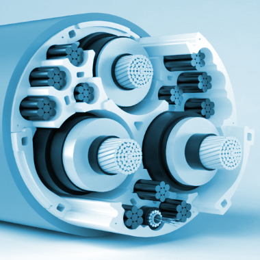
 | Subsea Umbilicals | T084-EN004 | ||
REVISION 05 | STATUS B |  | ||
 |
| 05 | 08/02/19 | JSO | Approved | CGA | VLE | BCA | - |
| 04 | 08/02/19 | CDA | Re-Issued for Approval | CGA | VLE | BCA | - |
| 03 | 12/02/08 | GCO | Approved | LGS | AAL | BCA | - |
| 02 | 31/10/07 | GCO | Issued For Approval | LGS | AAL | BCA | - |
| 01 | 01/08/07 | LGS | Issued For Comments | GCO | AAL | BCA | - |
| 00 | 16/07/07 | LGS | Internal Check | GCO | AAL | - | - |
| Rev. | Date | Issued by | Revision memo | Checked by | Approved by | ||
|---|---|---|---|---|---|---|---|
| Engineer approval | Total approval | ||||||
Contents
- 1. Introduction
- 2. Interface Requirement
- 3. Umbilical Technology & Manufacturers Review
- 3.1. General
- 3.2. Functions and Dedicated Lines
- 3.3. Power and control umbilical
- 3.4. Thermoplastic hose umbilical
- 3.5. Steel tube umbilical
- 3.6. Integrated service umbilical
- 3.7. Integrated Production Umbilical
- 3.8. Umbilical reliability and redundancy of functions
- 3.9. Subsea termination interface
- 3.10. Subsea bend restrictor
- 3.11. Topside bend stiffener
- 3.12. Topside termination system
- 3.13. External corrosion protection
- 4. Test Requirement
- 5. Installation Techniques
- 6. Applications & Limitations
- 7. Advantages & Disadvantages
- 8. Deepwater Steel Tube Umbilical Design Issues
- A. Manufacturer lists
List of Figures
- 2.1. Pull-in winch general arrangement
- 2.2. Seal plug
- 2.3. Topside hang-off arrangement
- 2.4. Typical arrangement of joint box for a steel tube umbilical
- 2.5. ISU termination head general arrangement
- 2.6. Connection system using subsea termination head and clamp assembly to connect integrated service umbilical to subsea structure (Aker Solutions)
- 2.7. Connection system using umbilical termination unit and ROV operated junction plates
- 2.8. Wet mateable connection principle applied to electrical cable
- 2.9. Controlled Environment (CE) Connector (by courtesy of Tronic)
- 2.10. Umbilical laying vessel: SUNRISE 2000 (Decommissioned in 2016) (Technip)
- 2.11. Umbilical laying equipment for ISU
- 3.1. Sample of different umbilical types
- 3.2. Helical lay-up machine for steel tube umbilical
- 3.3. Extruding machine
- 3.4. Armouring machine
- 3.5. Helical lay-up machine for Integrated Service Umbilical (Aker Solutions)
- 3.6. Hose braiding machine
- 3.7. Oscillatory (SZ) Lay-up
- 3.8. Typical structure of electro-hydraulic umbilical
- 3.9. Typical power supply umbilical including fibre optic cores for control system
- 3.10. Dynamic power and control umbilical
- 3.11. TECHNIPFMC Umbilical for West Shetland project
- 3.12. Medium Voltage (MV) power cable copper conductor (cross section)
- 3.13. Typical flexible hose structure
- 3.14. Dynamic electro-hydraulic (left) and Static hydraulic (right) thermoplastic umbilicals
- 3.15. HCR Hoses and Termination Cross Section
- 3.16. Typical hydraulic steel tube umbilical (for both static and dynamic applications)
- 3.17. Dynamic electro-hydraulic steel tube umbilical
- 3.18. Dynamic and static electro- hydraulic steel tube umbilical
- 3.19. Conventional integrated service umbilical (ISU)
- 3.20. Aker Solutions integrated service umbilical
- 3.21. Electrical cables position in a thermoplastic umbilical
- 3.22. Electrical cables position in a typical steel tube position
- 3.23. Electrical cables position in a integrated service umbilical
- 3.24. Cross section of DALIA production umbilical (TECHNIPFMC design)
- 3.25. Typical IPU design
- 3.26. Extruded IPU during fabrication phase
- 3.27. Subsea termination interface arrangement
- 3.28. Integrated service umbilical equipped with steel bend restrictor
- 3.29. Bend restrictor schematic
- 3.30. Polyurethane bend limiter
- 3.31. Topside bend stiffener
- 3.32. Topside termination of steel tube termination
- 4.1. Umbilical qualification tests (TECHNIPFMC)
- 5.1. Different umbilical configurations in Deepwater field development
- 5.2. CSO Sunrise 2000m flexible & umbilical lay vessel
- 5.3. Umbilical laying spread general arrangement
- 5.4. Umbilical installation from subsea manifold to subsea tree
- 5.5. Umbilical installation with first end initiation at subsea structure
- 5.6. Umbilical installation with first end initiation at floater
- 8.1. Steel tubes ISU finite elements models and analysis (TECHNIPFMC)
List of Tables


