5 Installation Techniques
5.1 General
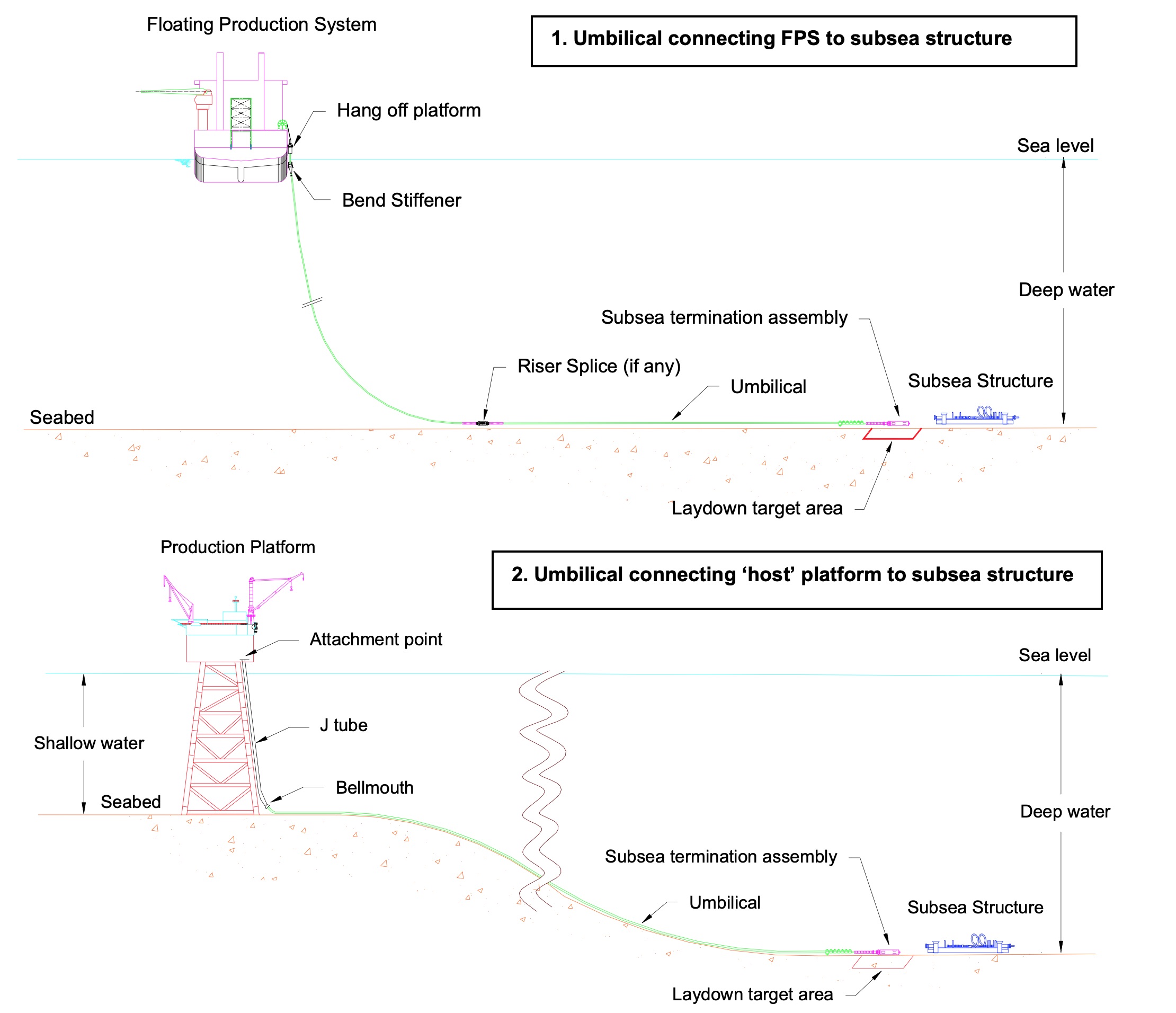
Deepwater field development uses subsea drilled and completed wells tied back to fixed structures in shallower water or floating production systems in deep waters. The tie back connections may be performed directly or through a subsea manifold.
These subsea trees are monitored and controlled via umbilical suspended in a catenary shape and protected at the splash zones by I/J tubes fixed to the structures as illustrated in Figure 5.1, “Different umbilical configurations in Deepwater field development”.
![[Tip]](tip.png) | Tip Click these links below for access to 3D resources: |
Umbilical are installed from an umbilical/flexible pipe installation vessel and can be deployed from two distinct umbilical laying spreads, depending on the line structure limitation and the lay tensions:
in-line tensioners;
directly from the storage reel.
For Deepwater applications, typical steel tube umbilical can have a large size of over 100mm OD (i.e. 110 mm – 320 mm) and high lay tensions varying between 30 tons and up to 150 tons at 2000m water depth.
Based on the umbilical crush resistance test (see Section 4.3) and a typical usage factor of 0.67 (or safety factor, refer to API 17 J), an allowable compression load is defined.
Both, umbilical lay tension and allowable compression load will determine the required (dual-track) tensioner contact length or the number of tensioners to provide the equivalent contact length.
When the required contact length is higher than 10 m – 12 m, there is a clear advantage to lay the umbilical directly from the storage reel, which must be rated for the lay tensions.
As for rigid pipe, the steel tube umbilical must be laid as per the rules for submarine pipeline systems, and more specifically in accordance with the following criteria:
Maximum 2% cumulative strains (reeling, unreeling, straightening, etc);
Large radius overboarding chutes (e.g. 14 m) to keep the ‘as laid’ umbilical steel tubes within the elastic domain (or less than 1% residual strain), with typical 3°-5° departure angle.
Static umbilical can also be integrated in a flowline bundle and installed by the towing method.
With regard to the repair topic, the only known method is to recover to surface the termination heads or the umbilical for repair; there is no underwater repair technique alternative.
The following sections will cover the current umbilical installation method using DP vessel equipped with suitable equipment for the work and related laying technique and procedures.
5.2 Laying equipment
Umbilical can be laid directly from a storage reel or via a tensioner system and associated carousel basket (see Figure 5.3, “Umbilical laying spread general arrangement”) installed on main deck or inside the installation vessel.
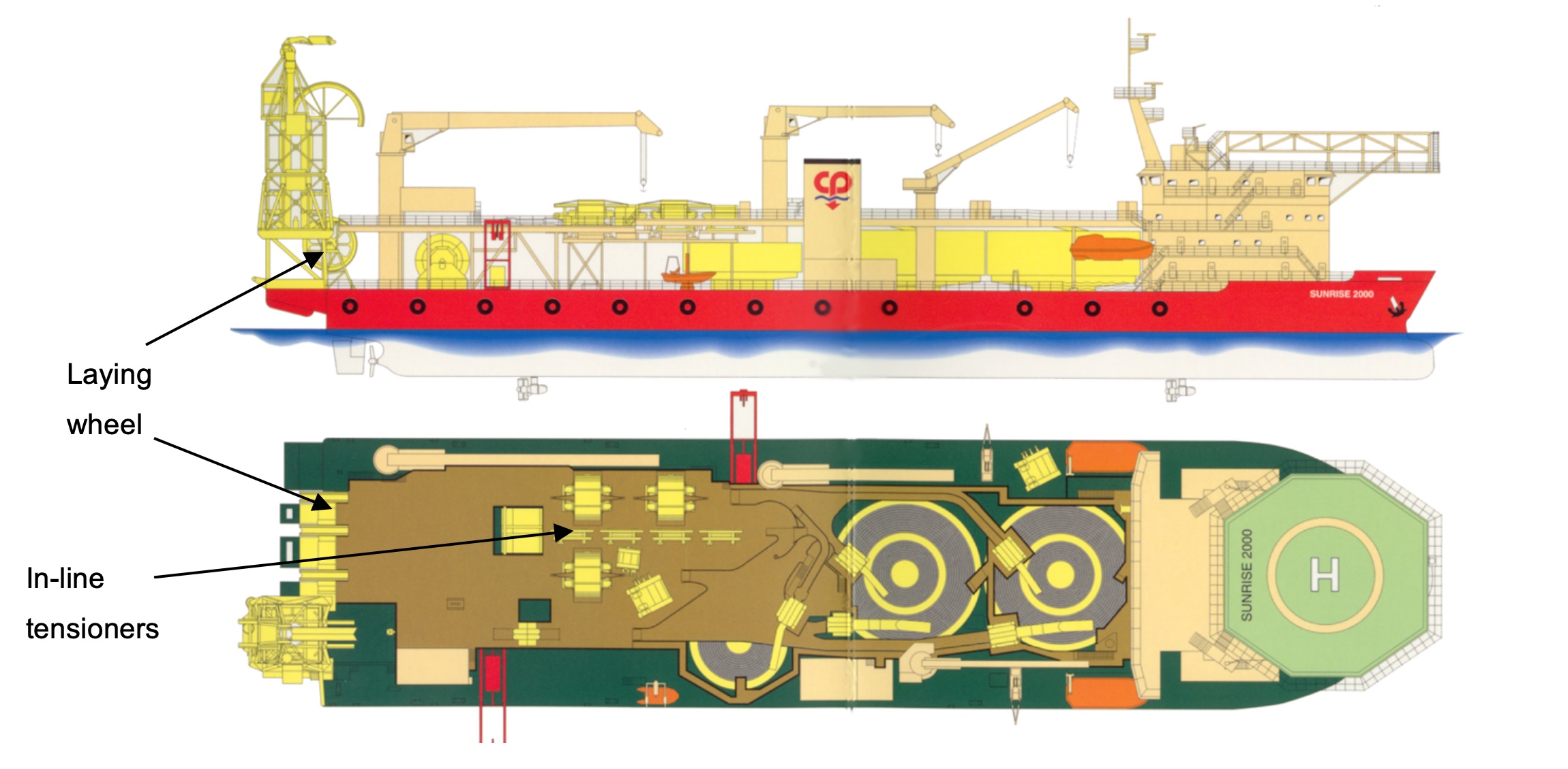
The umbilical is deployed and over-boarded from a stern laying wheel, similar in shape and dimensions to the flexible one (i.e. Technip Sunrise 2000, Figure 5.2, “CSO Sunrise 2000m flexible & umbilical lay vessel”), or from an over-boarding chute located at the stern or on the side of the vessel as illustrated in Figure 5.3, “Umbilical laying spread general arrangement”.
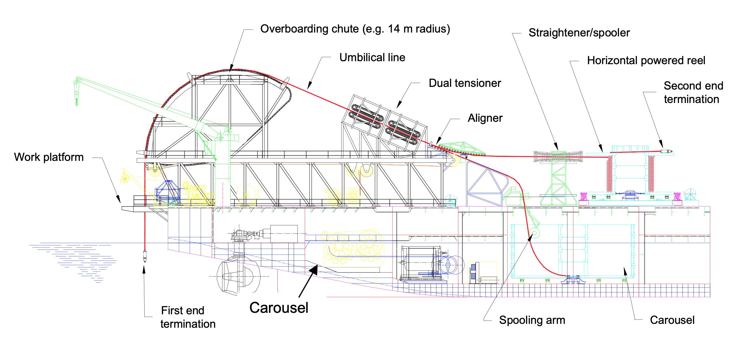
The umbilical lines are stored in a rotating basket in one or several segments and are routed towards the tensioning system via a spooling and deflector system. A straightening function will be added to the spooling system in case of integrated service umbilical deployment.
When umbilical are laid directly from the storage reel rated to hold the full catenary tension, the line is spooled out from the top of the reel with a spooling device.
The umbilical tensioning spread consists of individual in line tensioners over the working deck.
Both the umbilical laying reel with associated spooling system and the umbilical tensioning spread are controlled from the operation control room, in synchronization with deployment of the flowlines in case of a dual lay. The storage basket and the associated spooling system is operated generally from an individual control cabin.
The umbilical abandonment is performed with a winch fitted with adequate cable length and size related to water depth and laying tension.
Abandonment of the umbilical line on the seabed is achieved using a ROV remotely controlled disconnector or an acoustic release hydraulic shackle.
A deck crane (or A-frame) provides a direct access over the outside of the umbilical laying wheel or overboarding chute. The proper outreach of the crane facilitates the overboarding of umbilical connection or large termination unit.
5.3 Laying methods and procedures
5.3.1 General
Umbilical are laid using one of the following typical methods:
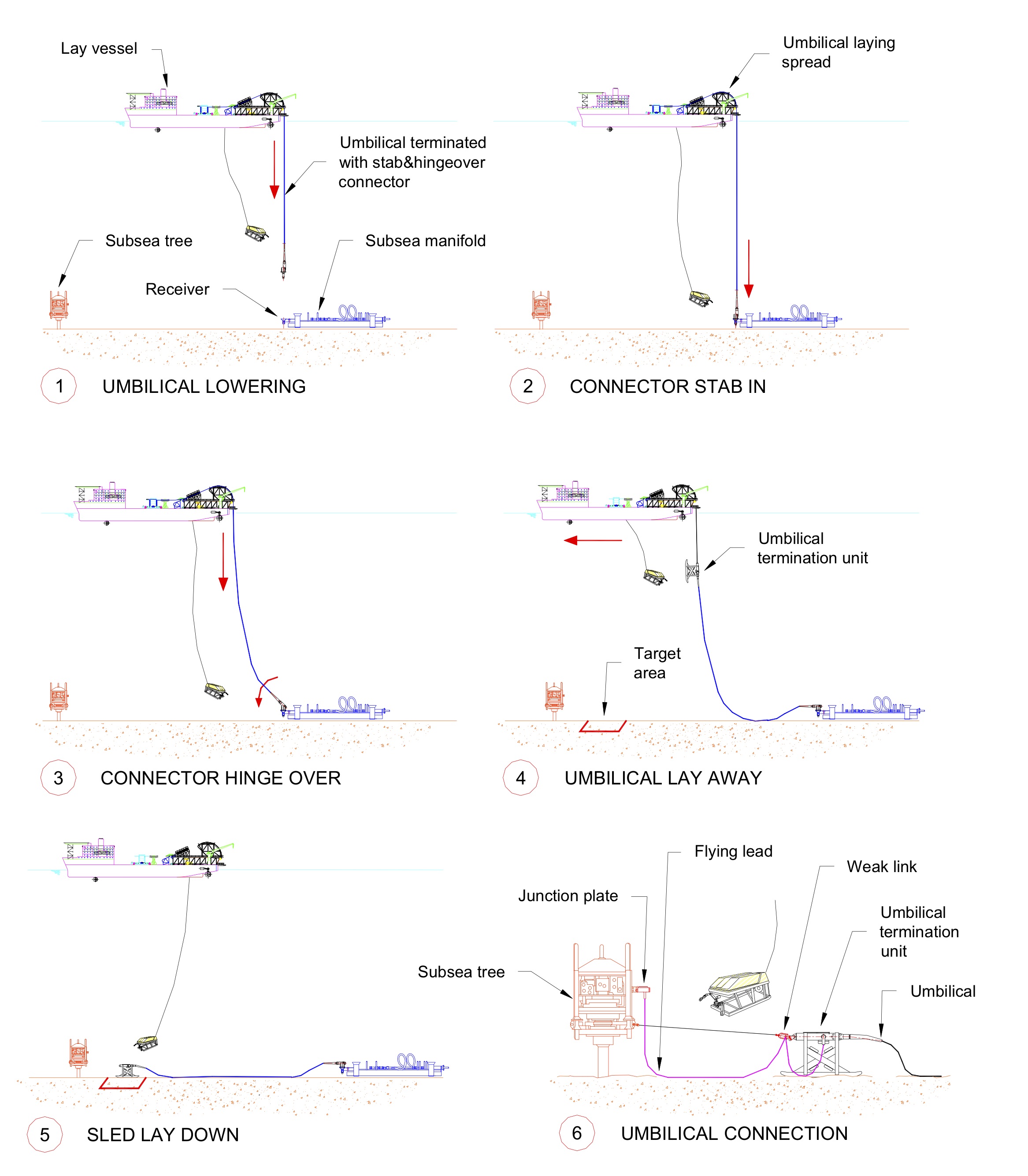
Umbilical is initiated at the manifold with a stab and hinge over connection or a pull-in/connection method and terminated near the subsea well with a second end lay down sled (i.e. infield umbilical connection from manifold to satellite well). The connection between the umbilical and the subsea well is later performed using a combination of the following Tie-in methods: (1) rigid or a flexible jumper, (2) junction plates and (3) flying leads (see Figure 5.4, “Umbilical installation from subsea manifold to subsea tree”).
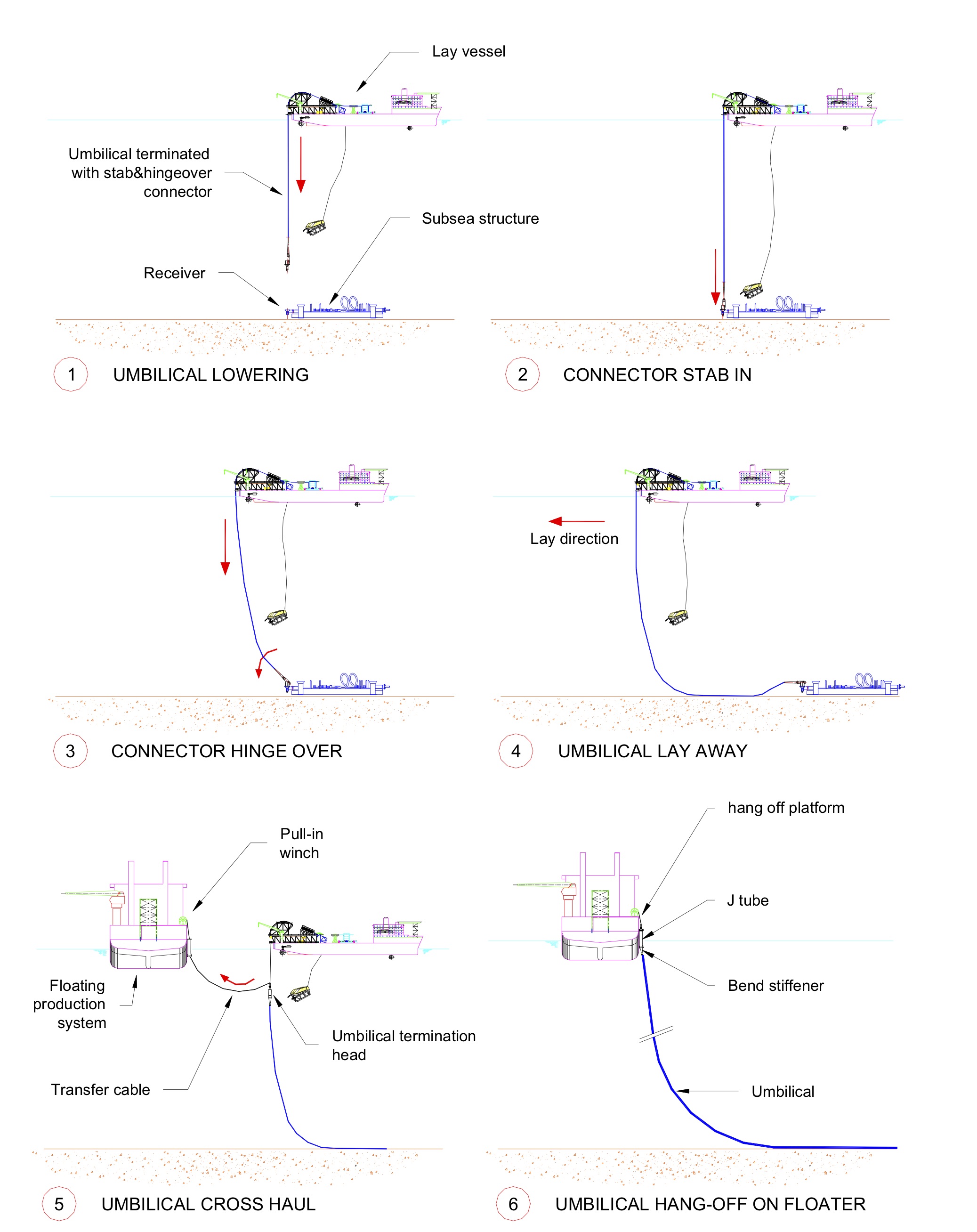
Umbilical is initiated at the manifold with a stab and hinge over connection or a pull-in/connection method. It is laid in the direction to the fixed or floating production system and pulled through an I/J tube or cross hauled from the laying vessel to the floating production vessel (see Figure 5.5, “Umbilical installation with first end initiation at subsea structure”).
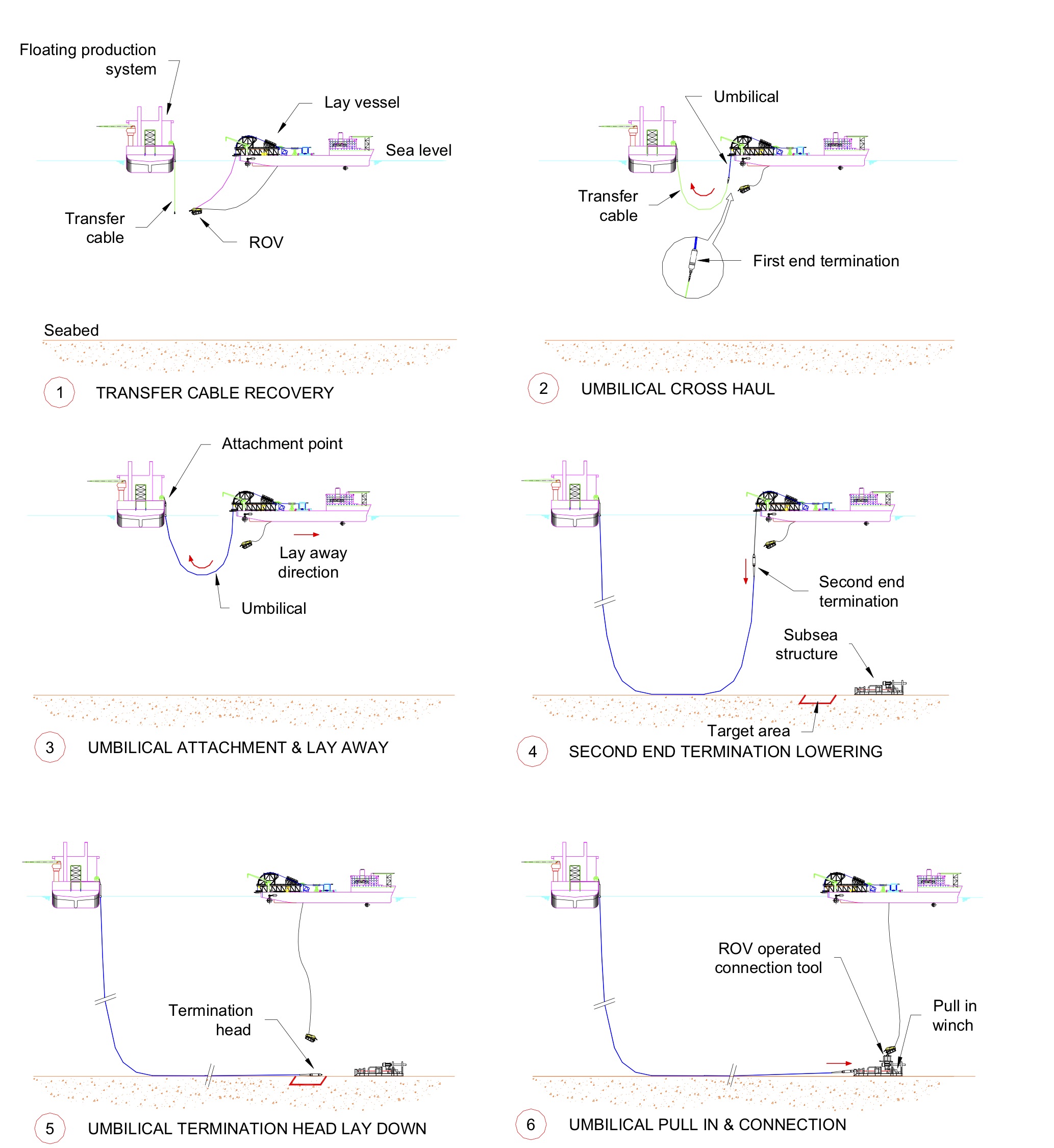
Umbilical can also be initiated at the fixed or floating production system and terminated near the subsea structure with a second end umbilical termination assembly (i.e. termination head, lay down sled, umbilical termination unit, etc.). A pull-in and connection tool operated by ROV may be used to connect the umbilical to the subsea structure (see Figure 5.6, “Umbilical installation with first end initiation at floater”).
For further information on connection technique please refer to Document “Tie-in Methods” Ref.[30].
For further information on laying vessels please refer to Document “Deepwater Installation Vessels” Ref.[29].
The fabricated umbilical length must be accurately determined for installation purpose based on:
On site route survey (seabed bathymetry, pockmarks, seabed debris and obstruction, etc)
Overlength (typically 2% - 5%) to mitigate for measurement accuracies of baselines (e.g. DGPS, acoustic) and electronic equipments.
For steel tube umbilical and for Deepwater installation, the internal fluid temperature drop from surface (up to 40°C in West Africa) to seafloor at 4°C will induce fluid volume reduction. In which case, potential tube collapse, under hydrostatic pressure at seabed must be addressed, or fluid volume compensation must be provided during the installation sequences.
The installation sequences associated with the above umbilical laying methods are further described in the following section.
5.3.2 Installation procedures
5.3.2.1 Umbilical installation between subsea manifold and X-tree
Method 1: The installation sequence would consist of the following phases (see Figure 5.4, “Umbilical installation from subsea manifold to subsea tree”):
The first end of the umbilical is initiated with a stab & hinge-over Connector at the subsea manifold equipped with a stab & hinge-over receiver.
When the stab & hinge-over connector is fully engaged and locked in its receiver, the installation vessel moves ahead slowly to perform the hinge-over operation.
During the hinge-over operation, the correct rotation of the connector and landing of umbilical on seabed is monitored by ROV.
On completion of hinge-over phase, normal umbilical laying continues until lowering of second end termination unit or sled on seabed.
Once the sled is laid down in the target area, its position is confirmed by ROV and acoustic metrology.
When the sled abandonment and disconnection of A&R winch cable are completed, the connection of the umbilical to the subsea structure is performed by ROV using flying leads terminated with junction plates.
![[Note]](note.png) | Note As part of above step 4, when approaching the target area from a distance of 2 – 3 times the water depth, the remaining umbilical length (in surface) is to be cross checked with the remaining lay distance (by means of acoustic baseline). This will allow the umbilical over length to be stored in curves on the seafloor, prior to the lay-down of the sled/umbilical termination unit in the target area. |
5.3.2.2 Umbilical installation with first end initiation at subsea structure
Method 2: The installation procedure would consist of the following phases (see Figure 5.5, “Umbilical installation with first end initiation at subsea structure”):
Lowering of the umbilical with its stab & hinge-over Connector using the umbilical laying spread located at the stern of installation vessel.
Stab and lock the connector in the receiver mounted on the subsea structure.
Move the vessel in the laying direction while paying out on umbilical to perform the hinge-over operation.
On completion of hinge-over operation, ROV will check the correct landing of the umbilical on seabed before resuming the normal umbilical laying operation. Umbilical is paid out until the vessel takes position for the transfer of umbilical to the floater.
When the transfer cable is recovered from the floater, connect the pull-in line to the pull-in head mounted on the umbilical and start the transfer of the umbilical to the floater.
Once load transfer is completed, recover A&R winch cable, resume pulling the umbilical through I/J tube and secure the umbilical to the hang off platform.
| Note The same note for umbilical over-length (see 5.3.2.1) is applicable during above step 4. |
5.3.2.3 Umbilical installation with first end initiation at floater
Method 3: The installation sequence would consist of the following phases (see Figure 5.6, “Umbilical installation with first end initiation at floater”) :
A transfer cable is passed from the floating production system to the installation vessel by means of ROV.
The first end umbilical termination is transferred to the floater with the dynamic part of the umbilical by pulling it through the I/J tube attached to the floater structure.
The first end termination is secured to the hang off platform while paying out of the umbilical continues.
Normal umbilical laying operation continues until the lowering of the second end umbilical termination on seabed.
On completion of second end umbilical termination lay down in target area, ROV will confirm its position before removing the A&R winch cable.
If the umbilical is terminated with a termination head, the Tie-in method will consist in first performing the pull –in of the termination head in the subsea structure then its connection to the structure by means of ROV operated tools or running tools to be deployed from the surface vessel.
If the umbilical is terminated with a termination unit/lay down sled, the Tie-in method is performed by ROV using jumpers and flying leads.
| Note The same note for umbilical over-length (see 5.3.2.1) is applicable during above step 4. |