2 Interface Requirement
2.1 General
The main interface requirements (for detailed review and assessment ) in the umbilical design are related to:
The above requirements are described in the following sections.
2.2 Floating Production System
Typical standard equipment on the floating production system includes:
I/J tube and bending stiffener / bell-mouth / gutter / restrictor;
I/J tube sealing (entrapped water heat);
Topside pull-in winch;
Topside hang-off assembly and connection.
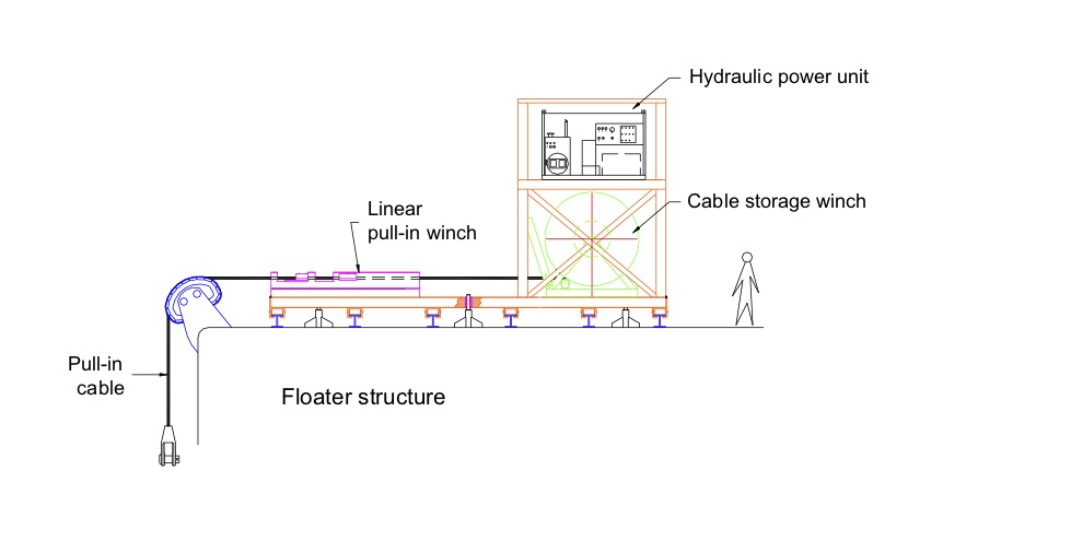
2.2.1 I/J tube and pulling winch
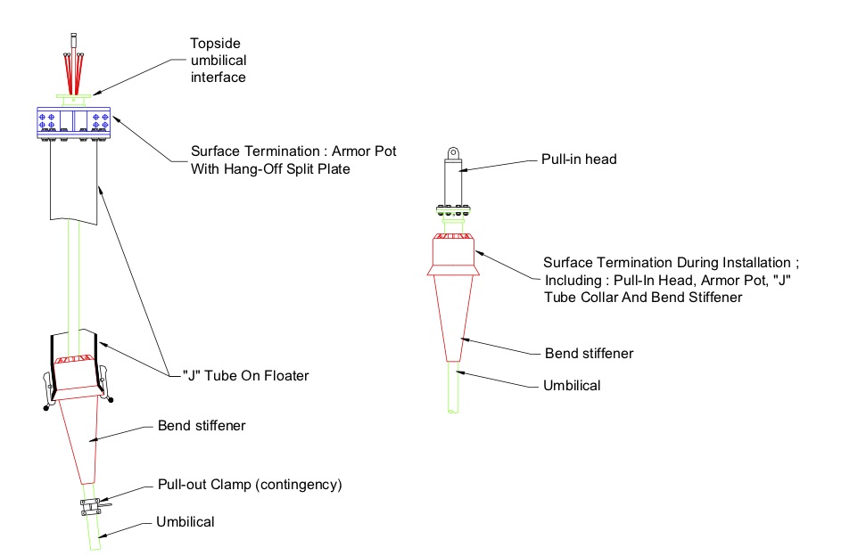
Flexible or steel tubes umbilical comprising power, signal and fluid lines are frequently brought into topsides through steel I/J tubes pre-installed on the pontoon or deck level of the floating production system. This is performed using a winch located above the J-tube, which draws a cable attached to the nose/pulling head of the umbilical (see Figure 2.1, “Pull-in winch general arrangement”).
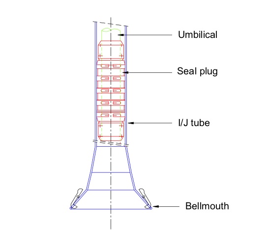
The I/J tubes are designed to protect the umbilical against environmental loads at the splash zone (wave and current), fires and accidental collisions with vessel. They are often equipped with a bell-mouth system using mechanical dogs to hold the umbilical bending limiter with a conical structure (see Figure 2.2, “Seal plug” and Figure 2.3, “Topside hang-off arrangement”).
2.2.2 I/J Tube seal
The I/J tube seal centralises the umbilical at the I/J tube entry and provides a seal against sea water, preventing dilution of corrosion inhibitors (see Figure 2.2, “Seal plug”). The seal can be (preferably) pre-installed on the umbilical or diver installed during installation.
The I/J tube seal can either be delivered as a moulded or packer-type sealing element.
![[Note]](note.png) | Note I/J tube seal plugs are not so often used in Total applications. This solution is not considered as recommended by Total as it may generate design and installation issues. |
2.2.3 Topside hang-off assembly
The topside hang-off assembly provides a structural element to transfer the pull-in loads from the umbilical during installation and into the platform J-tube after the installation is completed (see Figure 2.3, “Topside hang-off arrangement”).
2.3 Intermediate connection
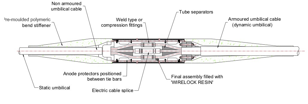
The umbilical riser splice is the connection between the dynamic and static part of the umbilical. This intermediate connection is always located on area where the connection and umbilical will be permanently resting on the seabed as this intermediate connection shall never be located in a dynamic section. The unit comprises suspension points, and connects the tubes with threaded type fitting or welded splices for both steel tubes and electrical cables. The riser splice also has oil-filled, pressure-compensated chambers containing electrical penetrators (see Figure 2.4, “Typical arrangement of joint box for a steel tube umbilical”). This device is mainly used when the static and dynamic cross sections of the umbilical are different or when the umbilical is too long to be fabricated in one-piece length. The intermediate connection is mainly performed offshore, onboard the laying vessel.
2.4 Subsea production system
Deepwater subsea umbilical termination system is either a termination head (see Figure 2.5, “ISU termination head general arrangement”) or termination unit (see ) depending on the type of umbilical (hydraulic umbilical, electrical umbilical, electro-hydraulic umbilical, integrated service umbilical etc.) and selected Tie-in method.
The complete subsea termination system comprises the following elements:
Subsea termination interface;
Bend restrictor/ bend stiffener hang off (bend restrictor/limiter is also possible);
Tubing support, including check valves, flanges, etc;
Electrical penetrators and Connectors.
Figure 2.5 - ISU termination head general arrangement
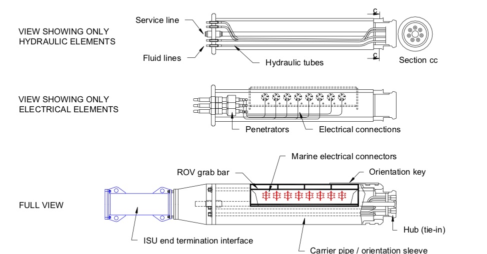
The electrical penetrators and Connectors are placed inside an oil-filled, pressure-compensated chamber. With respect to the electrical cables, the philosophy of using a minimum of two barriers against water ingress is maintained throughout the entire system.
The subsea termination system is typically manufactured in mild steel, painted and cathodically protected.
The design of the subsea termination system is related to the selection of one of the three following connection methods from the subsea end of the umbilical to the subsea structures:
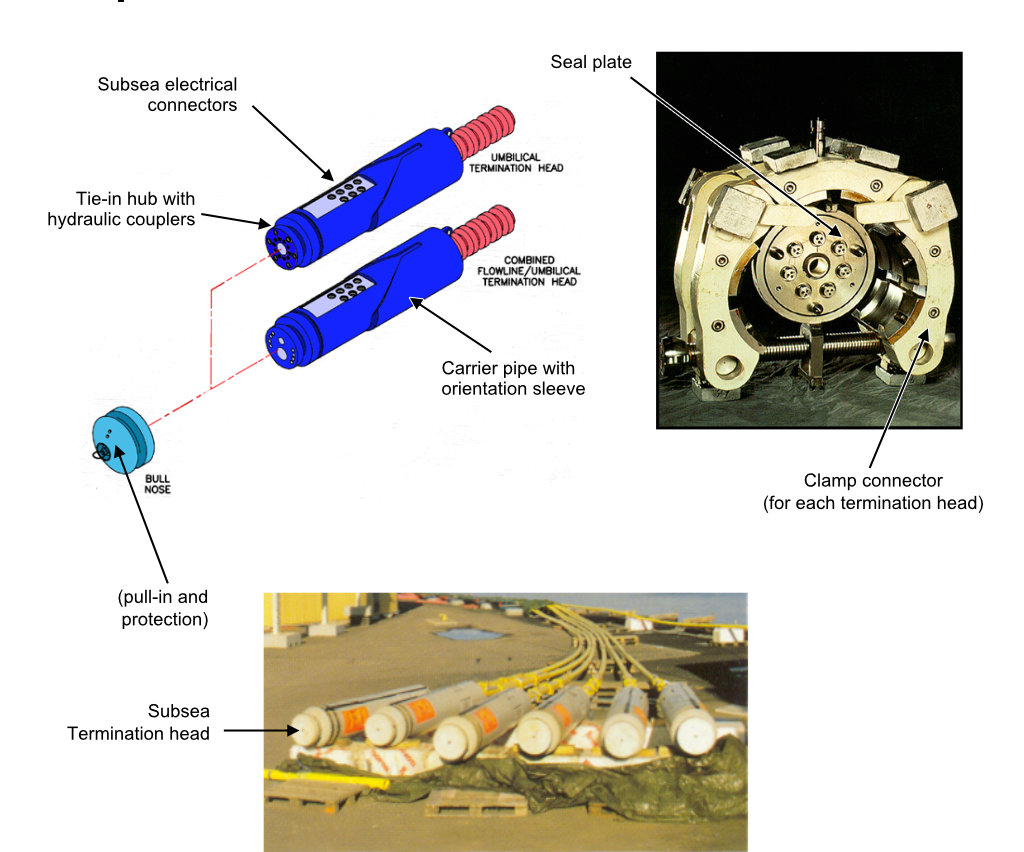
Clamp or collet connection: The installation of the umbilical can be based on either a stab and hinge-over method or direct pull-in method. The chosen connection method will have an impact on the design of subsea structure and connection system. For further information on subsea structure interface requirements, please refer to document "Tie-in Methods" (Ref.[30]). This type of connection is mainly used for the hydraulic umbilical with a high number of lines or high stiffness of the individual lines, which make the use of jumpers difficult (e.g. Integrated Service Umbilical) (see Figure 2.6, “Connection system using subsea termination head and clamp assembly to connect integrated service umbilical to subsea structure (Aker Solutions)”).
Figure 2.6 - Connection system using subsea termination head and clamp assembly to connect integrated service umbilical to subsea structure (Aker Solutions)
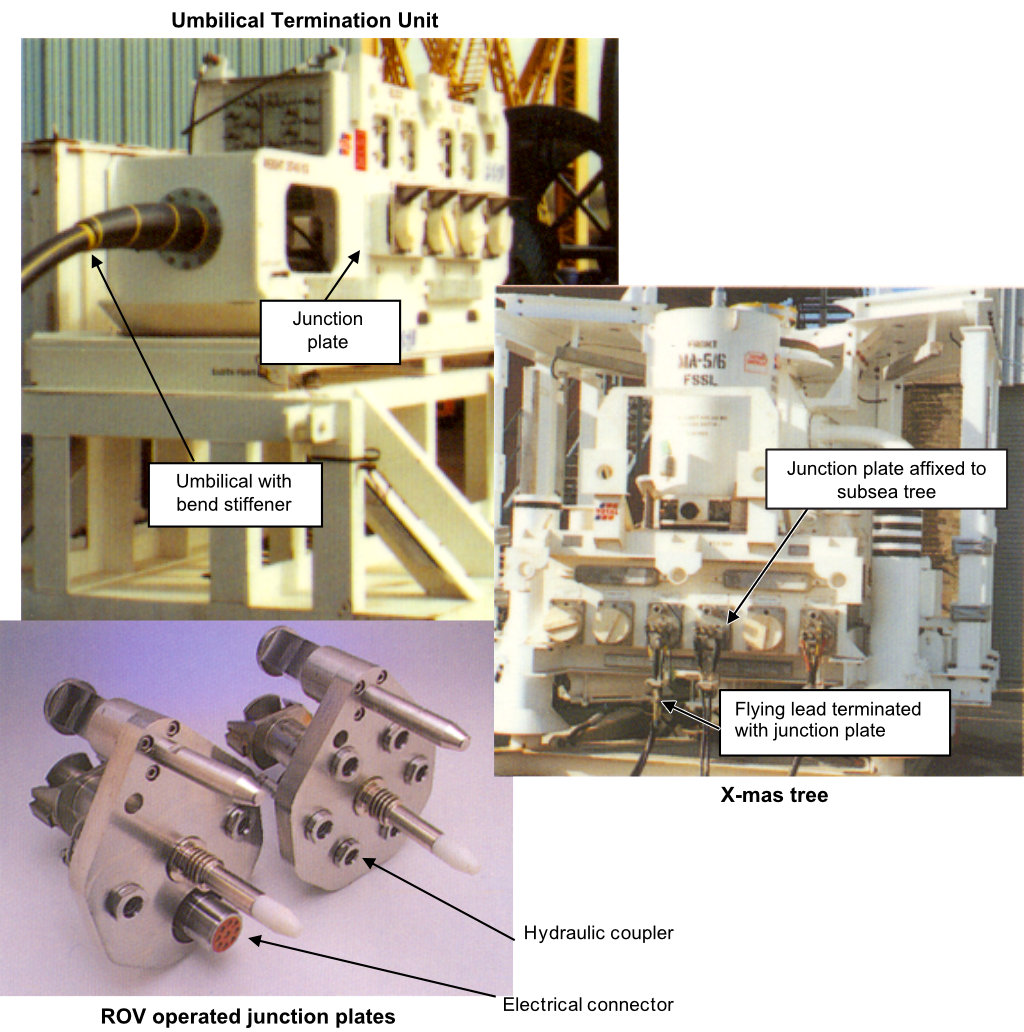
ROV-installed junction plates: The ROV-operated junction plate assembly consists of independent junction plates attached to mechanical arms which pivot on joints that are fixed to subsea structures or mounted on retrievable subsea control pods. Female coupler junction plates are generally mounted on the subsea structures such as tree, control pod, umbilical termination system, etc. Flexible jumpers allowing the subsea connections from subsea umbilical termination system are fitted at both ends with male coupler junction plates (see Deepwater subsea umbilical termination system is either a termination head (see Figure 2.5, “ISU termination head general arrangement”) or termination unit (see Figure 2.7, “Connection system using umbilical termination unit and ROV operated junction plates”). The subsea connection is performed using ROV and its dedicated tooling package in ‘free-flying mode’. It is therefore applicable only for electrical and/or hydraulic ‘flying leads’. This technique (i.e. ‘free-flying mode’) is not applicable to the Integrated Service Umbilical due to its central service line stiffness and termination head weight.
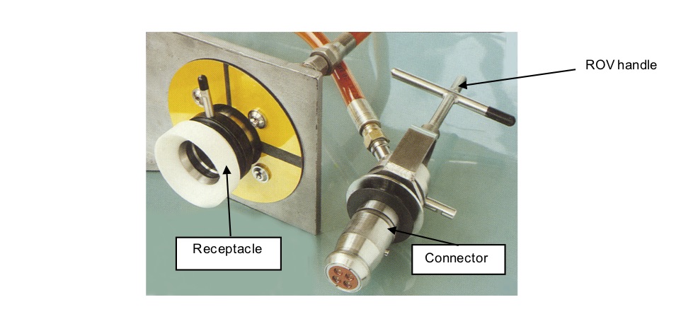
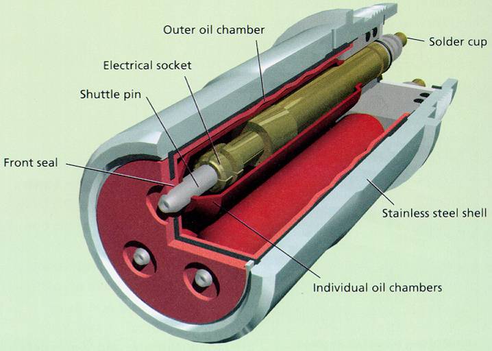
Subsea flying lead : Electro-hydraulic connections between subsea installations can be accomplished with an ROV-installed flying leads (see Figure 2.8, “Wet mateable connection principle applied to electrical cable”). A flying lead is deployed subsea using a compact frame. The ROV pulls one end of the flying lead from the frame and swims to the receptacle mounted on the subsea structure. Then the ROV returns to the deployment frame and pulls the other end of the flying lead and swims and connects it to the subsea umbilical termination unit or subsea termination assembly. This connection method is well suited for umbilical with a limited number of small hydraulic lines or electrical cables.
![[Tip]](tip.png) | Tip Click these links below for access to 3D resources: |
2.5 Deep Water Electrical Connectors
The electrical connections for low and high power are based on the fluid filled Connector concept. The controlled environment (CE) plug concept removes seawater from contact with the critical components (refer to [30]).
Electrical and optical cables are now suitable with ultra deep water applications. Electrical cables and their connectors have already been qualified for 3000m Water Depth.
2.6 Caps
The umbilical is provided with protection caps and preservation caps installed on the subsea termination system. The purpose of the protection cap is to provide mechanical protection and prevent contamination of the connectors and seals faces. The purpose of the preservation cap is, in addition to mechanical protection, to enable pressurisation of the fluid lines above the ambient hydrostatic pressure in order to compensate for pressure variations in the lines during laying operations and prevent ingress of dirt and moisture.
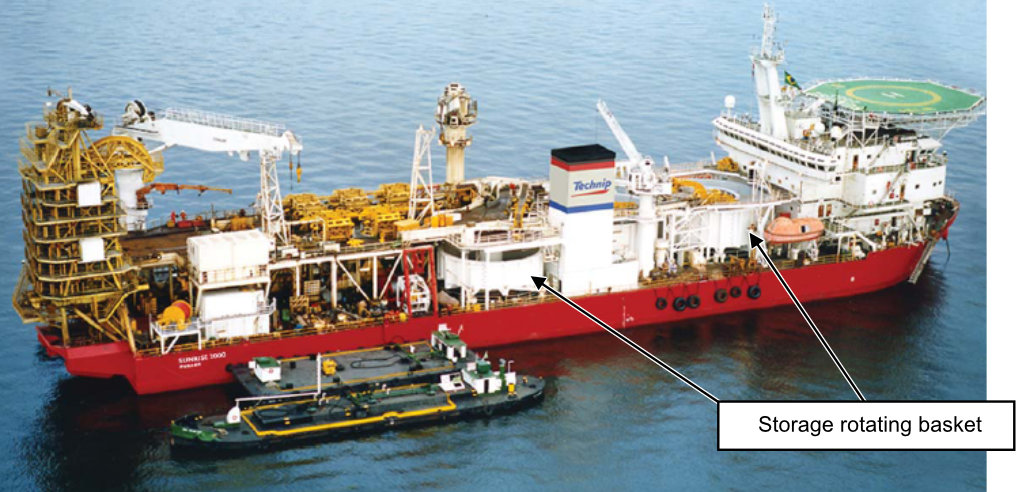
2.7 Laying vessel and equipment
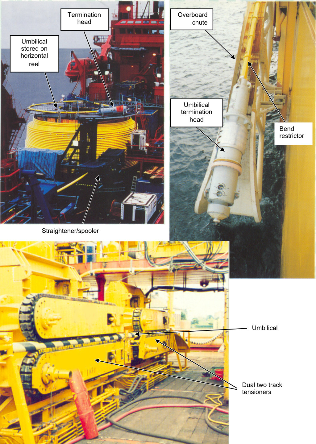
The equipment required for the umbilical laying from an installation vessel (see Figure 2.10, “Umbilical laying vessel: SUNRISE 2000 (Decommissioned in 2016) (Technip)” and Figure 2.11, “Umbilical laying equipment for ISU”) is listed below:
Horizontal powered reel, vertical powered reel or carousel for the storage of umbilical (Integrated service umbilical and steel tube umbilical will be mainly stored in horizontal powered reel);
Straightener / spooler to assist in loading and unloading the umbilical. The straightening function is only required for the laying of integrated service umbilical/steel tube umbilical;
Tensioner / aligner to align the umbilical with the tensioner central axis and retain the laying load tension;
Overboard chute to control the umbilical curvature;
A&R winch to abandon umbilical on seabed and recover it in case of problem.