
4 Test Requirement
4.1 General
To demonstrate that the functional core components and umbilical system will meet the performance requirements, a qualification/factory acceptance test program should be undertaken. This will cover material testing of each umbilical component through to umbilical performance verification.
4.2 Material qualification testing
The following typical test regime is performed on samples for qualification of functional core components to verify its performance according to the design specifications:
Steel tube material Criteria, purposes
Mechanical tests (Yield, Tensile, Elongation)
Tension loads, strains
Hardness test
Fatigues, cracks
Butt welded tube fatigue testing
Fatigue
Pitting corrosion test
Corrosion, life cycle
Flattening test
Loading, crushing
Flaring test
Fire resistant
Ultrasonic testing
Tension loads, fatigues
Metallographic examination for super duplex Ferrite content
sigma phase
Eddy current test
Fatigues, cracks
Burst test
safety limit to tensile stress
Proof pressure test
safety limit to yield stress
Electric cables
DC conductor resistance
line integrity
Insulation resistance
depth pressure, water-proof
High voltage DC
Function capabilities
Data transmissions
Check of data transmission performances which are typically:
between 1200 and 4800 bits per second (depending on total length) for a conventional copper wire signal, associated with a bit error of less than 1 in 10 bits.
about 55 Mbit.s-1 for optical cables and bit error rates of better than 10-9.
4.3 Umbilical design qualification testing
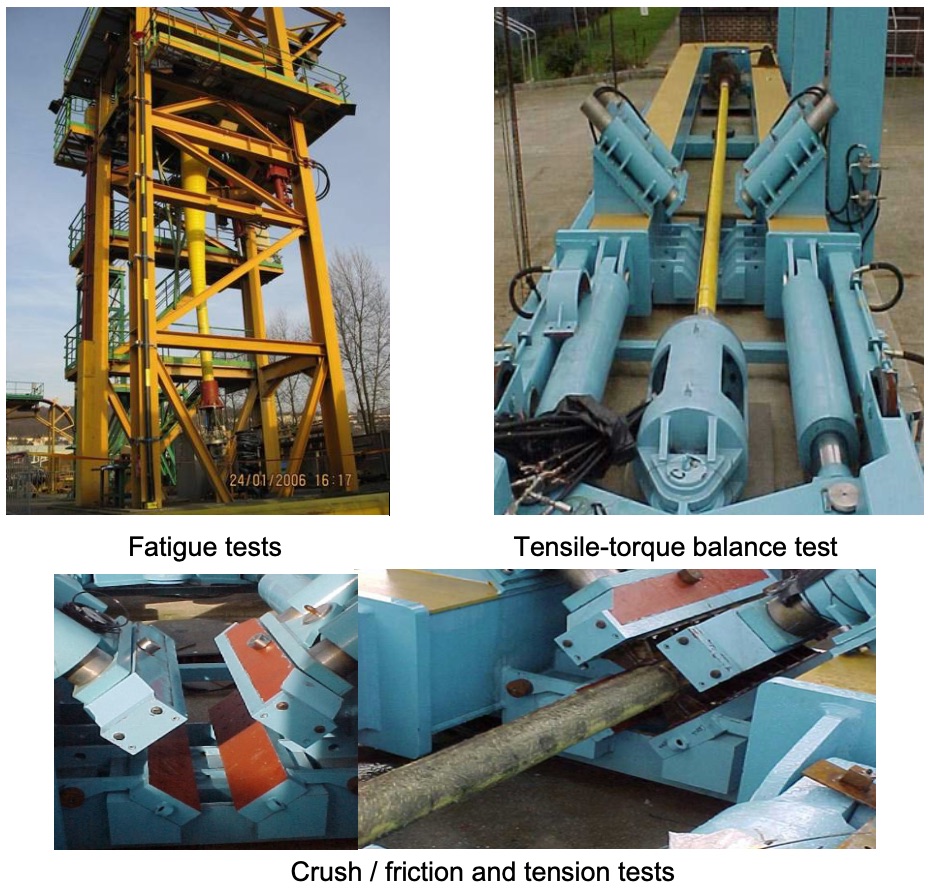
Sample lengths of prototype umbilical manufactured and tested prior to the fabrication of the final umbilical will prove mechanical performance of the umbilical design. The following tests are performed on dynamic umbilical prototype samples in the manufacturing facility:
Tensile breaking strength;
Reeling and straightening capacity (as regard to installation purposes);
Tensile/torque balance test;
Flex fatigue of umbilical and topside hang-off arrangement;
Crush friction and resistance test (installation parameters – see Chapter Chapter 5, Installation Techniques);
Bend stiffness test.
The steel umbilical prototype samples will include butt welded tube sections in order to verify the integrity of the welds under flex fatigue conditions. The performance criteria and cycles performed will be mutually agreed between umbilical manufacturer and operator, e.g. long term umbilical fatigue test minimum 106 cycles.
4.4 Acceptance testing
Extensive testing is carried out by the umbilical manufacturer at all stages of manufacture to ensure the finished products meet the required acceptance criteria and are fit for purpose.
The following tests are undertaken:
Steel tubes and thermoplastic hoses (full production lengths)
Visual inspection;
Dimensional checks;
Burst pressure test (samples only);
Proof pressure test (1.5 x design pressure).
Electric cables
Hydrostatic testing @ 35 bar.g of insulated conductors;
DC conductor resistance: consists in measuring electrical cable conductor resistance. The conductor resistance measurements shall be corrected for temperature and referred to 20°C. The accuracy of the conductor resistance measurements shall be in milliohm. Temperature correction and accepted criteria shall be in accordance with IEC publication 228;
Insulation resistance consists in measuring insulation resistance between conductors and to earth. Test voltage shall be minimum 500 volt DC and minimum acceptable insulation resistance shall be e.g. 1000 Mohms/km;
High voltage DC to verify the electric cable function performance;
Time domain reflectometry: this test is carried out to establish the cable signature and shall be used for detection of possible changes in this signature due to stress, damages, etc. during the fabrication and installation phases.
Umbilical
The following tests will be carried out on the finished umbilical before load out and those marked *, shall be repeated (as required) after loading onto the shipping/installation reel, during the installation phase and the subsea pre-commissioning phase. Results should be comparable to the previously performed tests (i.e. before load-out).
Electrical cables
DC conductor resistance* (minimum one loop during installation);
Insulation resistance*;
High voltage DC;
Time domain reflectometry*;
Hydraulic tests
Proof pressure test* and decay test (hoses);
Proof pressure test* (steel tubes);
Flow rate test in turbulent conditions (steel tubes and hoses);
Dimensional and visual (steel tubes and hoses);
Hydraulic fluid cleanliness (steel tubes and hoses)*.
Data transmissions
Check of data transmission performances.
![[Note]](note.png) | Note
|
4.5 Extent of flushing, pressure testing, cleaning & preservation
The requirements for flushing, pressure testing, cleaning and preservation for specific umbilical fluid lines are listed in Table 4.1, “Test requirements summary”:
Table 4.1 - Test requirements summary
Line Type | Flushing &Cleaning | Pressure test | Pickling * | Hot oil flushing | Flow test | Cleanliness | Preservation | ||||
|---|---|---|---|---|---|---|---|---|---|---|---|
Prefab | Prefab | FAT | Load out | Prefab | FAT | FAT | FAT | Load out | FAT | Load out | |
Chemical / service lines | X | X | X | X | X | X | X | ||||
Hydraulic lines | X | X | X | X | X | X | X | X | X | X | X |
* see Table 6.1, “Prediction life of liner material (50% life improvement for every 10°C reduction)”, section Section 6.1, “Thermoplastic hose umbilical”, thermoplastic hose
After incoming inspection and dimensional control a foam pig is driven through the steel tubes by dry filtered air, to verify cleanliness and remove any contamination before welding.
During welding (& reeling onto storage carousel) the tubing shall be equipped with special end fittings for flushing and hydraulic pressure testing. After pressure testing the tubing shall be thoroughly drained and dried by means of a wiper pig driven through the system by dry filtered air. The operation shall be repeated until the system is clean and dry (e.g. NAS 1638).
Immediately after drying, blind caps shall be mounted on the end fittings for protection during storage and transportation.
After assembly and welding into complete umbilical, another hydraulic pressure testing will be required for all lines.
When the pressure testing has been accepted and recorded, chemical cleaning (pickling) shall follow for the hydraulic lines. The chemical cleaning will be executed in three steps: acid cleaning, flushing and drying.
In addition the hydraulic lines shall be flushed with hot oil. During this operation a cleanliness verification and water content examination shall be executed by particle counting of the fluid in accordance with NAS 1638 Class 6.


