
SUBSEA PRODUCTION SYSTEMS | T084-EN003 | |||
REVISION 04 | STATUS C | |||
 |
| 04 | 17/04/19 | JSO | Approved | CGA | VLE | - | HEK |
| 03 | 07/03/19 | JSO | Issued For Approval | CGA | VLE | - | HEK |
| 02 | 12/02/08 | JOS | Issued For Approval | GCO | AAL | BCA | - |
| 01 | 23/05/07 | JOS | Issued For Comments | GCO | AAL | BCA | - |
| 00 | 27/04/07 | JOS | Internal Check | GCO | AAL | - | - |
| Rev. | Date | Issued by | Revision memo | Checked by | Approved by | ||
|---|---|---|---|---|---|---|---|
| Engineer approval | Total approval | ||||||
Contents
- 1. Introduction
- 2. Field Architecture
- 3. Subsea Wellhead Systems
- 3.1. Functions of Subsea Wellheads
- 3.2. Typical Subsea Wellhead System – General Description
- 3.3. Types of Subsea Wellhead Systems
- 3.4. Wellhead Connector Profiles
- 3.5. Tubing Spool Adapters
- 3.6. Typical Well Casing Programs
- 3.7. Wellhead Guide Structures
- 3.8. Loads on Wellheads
- 3.9. Subsea Wellhead Materials
- 3.10. Description of Typical Subsea Wellhead System Components
- 3.11. Wellhead Running Tools
- 3.12. Typical Subsea Wellhead Installation Procedures
- 4. Subsea Christmas Trees
- 4.1. Functions of Subsea Trees
- 4.2. Types of Subsea Trees
- 4.3. Components of a Typical Subsea Tree
- 4.4. Pressure and Structural Design Considerations of Subsea Trees
- 4.5. Tree Mounted Controls and Instrumentation
- 4.6. Subsea Tree Installation
- 4.7. Installation and Workover Riser Systems
- 4.8. Installation and Workover Control Systems
- 5. Manifolds and Connection Systems
- 6. Production Control System
- 7. General SPS Design Considerations
- 8. SPS Equipment Testing and Commissioning
- 9. Risk Assessment and Management
- A. SPS contractors
List of Figures
- 1.1. A Variety Of Field Development Options Exist as Subsea Technology Moves Into Deeper Waters.
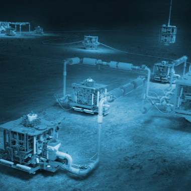
- 1.2. Subsea Production Systems Offer a Cost Competitive Option for Deepwater Field Developments (Girassol field, Angola, Total)
- 2.1. Examples of Host Platforms Available For Tieback
- 2.2. One Example of a Subsea Pumping Module (OneSubsea)
- 2.3. Three Types of Well Grouping, Single Well (Satellite), Well Pair and Cluster
- 2.4. Typical Well Cluster
- 2.5. Modular Template Manifold (Troll development)
- 2.6. Cluster Type field development (Moho Nord).
- 3.1. A Typical BOP Stack
- 3.2. Typical Subsea Wellhead System
- 3.3. Wellhead Profiles
- 3.4. Typical 13-3/8” Casing Hanger
- 3.5. Typical Casing Program
- 3.6. A Typical Guide Base
- 3.7. A Temporary Guide Base Being Deployed by a Running Tool on Drill Pipe
- 3.8. Example of a Retrievable Permanent Guide Base
- 3.9. Typical 30” Wellhead Housing
- 3.10. Typical 18-3/4” Wellhead Housing
- 3.11. A Typical Wellhead Stack-Up
- 3.12. neSubsea Model 70, High Capability (HC) and Deepwater (DWHC) Wellhead Connectors on Standard and Deepwater HC Wellhead Hubs, Connector Versatility and Hub Interconnectability
- 3.13. Typical Casing Hanger for Subsea Wellhead
- 3.14. A Typical Suite of Subsea Wellhead Running Tools
- 3.15. A Typical 30” Wellhead Running Tool
- 3.16. An 18”3/4 Wellhead Running Tool – Drill Quip
- 3.17. 30” Conductor Housing Running tool
- 3.18. Single Trip Tool
- 3.19. Casing Hanger Running Tool
- 3.20. 3.11.14. Mill Flush and Lead Impression Tool (Moho Nord, Aker Solutions)
- 4.1. Deepwater Horizontal XT (BHGE DHXT)
- 4.2. Horizontal and vertical Tree valves
- 4.3. Schematic Representations of Different Tree Types
- 4.4. Example of vertical tree (TechnipFMC - EGINA Production XT)
- 4.5. Example of vertical tree (Aker Solution – KAOMBO PVXT)
- 4.6. Valves body of vertical tree (Aker Solution – KAOMBO PVXT)
- 4.7. Deepwater Vertical Monobore Tree stacked on Tubing Hanger Spool (OneSubsea VMXT)
- 4.8. Horizontal Tree main body cross section (valves located on horizontal section)
- 4.9. Horizontal Tree (Dril-Quip)
- 4.10. Spool Tree or Horizontal Tree (OneSubsea)
- 4.11. Dual Bore Tree Stacked on Top of Tubing Adapter on Shop Floor
- 4.12. Dual Bore Split (Upper and Lower) Body Tree
- 4.13. Dual Bore Tree Being Deployed
- 4.14. Dual Bore Guidelineless Tree on Test Stand
- 4.15. Horizontal Tree with Trawl Protector Frame
- 4.16. Typical Fail Closed Subsea Actuator (Valve Not Shown)
- 4.17. Typical Valve Actuator with Rotary ROV Override
- 4.18. Examples of a Non-Retrievable Subsea Choke
- 4.19. Master Flo Choke
- 4.20. Examples of Dual Bore Tree Cap Running Tools
- 4.21. Typical Tree Running Tool for Mechanical Connector (Hydraulics Are In the Tool)
- 4.22. Re-entry hub (mandrel profile) at the XT top
- 4.23. Dual Bore Riser in a Typical Riser Shipping Basket
- 4.24. A Subsea Tree Being Deployed With An Installation And Workover Riser
- 4.25. Horizontal Tree Tubing Hanger
- 4.26. Typical Dual Bore Conventional Riser System with Associated Tools, Adapters, And Accessories
- 4.27. Typical Dual Bore Conventional Riser System with Associated Tools, Adapters, And Accessories
- 4.28. Dual Bore Riser Configured With Orientation Helix (Rotated 90 Degrees In View On The Right). The Tubing Hanger Running Tool Is Shown With The Riser On Right – Omitted On The Left.
- 4.29. A Dual Bore Riser System Configured To Run A Subsea Tubing Hanger Inside A Subsea BOP And Marine Riser
- 4.30. Typical Dual Bore Riser Configured With An Orientation Joint Ready To Run A Tubing Hanger. Note The Helix Clearly Visible At The Lower End Of The Riser And The Dual Pipe Above The Slick Joint.
- 4.31. Dual Bore Tubing Hanger Orientation Joint With “Slick Joint” Clearly Visible – Shown Being Lifted From Its Shipping Basket To The Rig Floor
- 4.32. How The Orientation Helix Interfaces With The Orientation Pin Installed On The BOP
- 4.33. Example Of A Spider For Running Installation And Workover Riser.
- 4.34. Dual Bore Riser Being Made Up At The Drill Floor. Note Use Of Dedicated Spider For Supporting The Already Suspended Riser.
- 4.35. Example Of A Spider Used To Run Dual Bore Risers
- 4.36. This Drawing Shows A Typical Spider Design
- 4.37. Typical Lower Marine Riser Package (LMRP) and Emergency Disconnect Package (EDP) On Its Test Stand.
- 4.38. A Basic Lower Marine Riser Package (LMRP)
- 4.39. A Basic Emergency Disconnect Package (EDP)
- 4.40. Typical Dual Bore Riser Standard Joint
- 4.41. Riser Tension Joint In Service In The Moon Pool
- 4.42. Typical Dual Bore Riser Standard Joint
- 4.43. A Photo Of A Simple Surface Tree (Or Flowhead) For A Dual Bore Riser System –Shown On Its Side.
- 4.44. Example Of A Simple Surface Tree (Or Flowhead) For Dual Bore Riser System
- 4.45. A Variable Length Tension Frame.
- 4.46. Surface Tree In The Derrick – Note The Man On The Sling At The Wireline BOP To Install The Lubricator Above The Surface Tree.
- 4.47. Typical Horizontal Tree Installation and Workover Riser System Deployed Inside a Subsea BOP Stack.
- 4.48. Subsea Test Tree With Disconnect Feature
- 4.49. Cut Away Section View of Subsea Test Tree (SSTT) Used With Horizontal Tree Riser Systems
- 4.50. Retainer or Riser Containment Valve
- 4.51. Lubricator Valve or Well Re-entry Valve
- 4.52. Example of a Mono-Bore Riser System
- 4.53. A Typical Surface Make-Up Subsea Umbilical Termination
- 4.54. Another Type Of Remote Make-Up Hydraulic Interface
- 4.55. A Typical IWOC HPU and Reel System
- 4.56. Typical Input Plate to an IWOC Reel
- 5.1. Example of a 4- Well Subsea Manifold With Flowline Connections
- 5.2. Deepwater Subsea Manifold With Multiple Flowline Connections
- 5.3. Example of manifold foundation (KAOMBO – Aker Solutions design)
- 5.4. Separate foundation and template base – exploded view
- 5.5. HOSTTM template manifold system (by courtesy of TECHNIPFMC)
- 5.6. Example of cluster manifold (KAOMBO - Aker Solutions design)
- 5.7. ROV mounted on ROVCON (TECHNIPFMC) Flowline Pull-in and Connection Tooling
- 5.8. Tool and connection head (left) and ROV and tool (right) (by courtesy of TECHNIPFMC)
- 5.9. Various vertical connection jumpers (by courtesy of OneSubsea (left) and OneSubsea/ Nexen Petroleum (right))
- 5.10. An example of a vertical make up mechanical connector with hydraulic running tool
- 5.11. Details of multibore collet (by courtesy of TECHNIPFMC)
- 5.12. 2-Piece McPACTM clamp (by courtesy of OneSubsea)
- 5.13. Single bolt 3-piece clamp connector (Aker Solutions)
- 5.14. Another View of a Typical Deepwater Pipeline End Manifold (PLEM)
- 6.1. K5F all electric subsea XT (OneSubsea all electric XT)
- 6.2. Example of a Direct Hydraulic Control System HPU and Panel for Six Subsea Wells
- 6.3. Production Control System - Overview
- 6.4. Master Control Station (MCS) for a Multiplexed Subsea Production Control System (GE VetcoGray)
- 6.5. Typical Electrohydraulic Subsea Production Control System Topsides Components
- 6.6. Typical Subsea Control Module (SCM)
- 6.7. Internal View of a Typical Subsea Pod – The Outer Housing Is Yet To Be Installed
- 6.8. Retrievable PT/TT sensor installed subsea (TECHNIPFMC Water Injection XT of EGINA Development)
- 6.9. Subsea multiphase flowmeter with recoverable electronic canister (in blue) (Emerson ROXAR MPFM)
- 6.10. An Example Of A TUTA –Topside Umbilical Termination Assembly– The Subsea Umbilical Starts At This Box On The Production Facility. The HPU Ties Into This Point To Supply Hydraulic Power.
- 6.11. Umbilical Armour Pot
- 6.12. Production static umbilical (left) – Dynamic power cable (right)
- 6.13. Umbilical Splice Connections. Left Photo is a Planned Field Quick Make Up Splice Kit. Right Photo is a Permanent Factory Splice -It Is Similar To a Repair Splice- the Cover is Not Shown on the picture above.
- 6.14. A Typical Subsea Control Umbilical Termination Assembly for Three Subsea Wells.
- 6.15. A More Complex Umbilical Termination Assembly for Several Wells –Note the Electrical Connections Are Not Included In This Sub Assembly.
- 6.16. Example of a Large Umbilical Termination Assembly with a Large EDU Included.
- 6.17. Diagram Of an Electrical Flying Lead with Typical ROV Wet Mate-Able Electrical Connectors
- 6.18. Diagram Of an Electrical Flying Lead with Typical ROV Wet Mate-Able Electrical Connectors
- 6.19. EFL connector (dual oil-filled) - connection sequence (TRONIC DigiTRON connector)
- 6.20. Picture of a UTA with A Hydraulic Flying Lead during Systems Integration Test.
- 6.21. Examples of Hydraulic Flying Lead junction plate
- 7.1. Chemical Injection Dosing Valve CIDV (SKOFLO)
- 7.2. Chemical Injection Dosing Valve CIDV fluid schematic (SKOFLO)
- 7.3. Typical subsea mated junction plates with hydraulic couplings, where the inboard plate contains the male couplers and is permanently mounted. The outboard plate contains the female couplers and the ROV bucket for installation interface.
- 7.4. Standard ROV torque buckets - the end effector inside the bucket is difficult to see in these photos. The end effector size and shape determines the torque ratings for the bucket - note the optional grab handles on the panel in the right hand photo
- 7.5. Single Point Docking TDU (Left) and Twin Point Docking TDU (Right)
- 8.1. A Typical Workover System SIT With The Subsea Tree


