
3 Subsea Wellhead Systems
The Subsea Wellhead system consists of the Seabed Conductor housing, the wellhead, Casing hangers, Annulus seal assemblies (pack-offs), guidance structure and various running tools. Drilling a subsea well from a floating drilling rig or completing a well subsea requires a subsea wellhead system.
3.1 Functions of Subsea Wellheads
The functions of the Subsea Wellhead system can be summarised as follows:
to support and seal to the subsea blowout preventer (BOP) during drilling
to support and seal to the subsea production tree
to support and seal to the well Casing.
to support and seal to the production Tubing Hanger (for XT on wellhead)
The Subsea Wellhead together with the BOP or the production tree provides the means to safely contain reservoir pressure during oil and gas drilling and production operations. It rarely sees actual reservoir pressure but is rated to withstand this pressure in case of loss of well control during drilling or a breach of a primary pressure barrier during production. Standard API pressure ratings in use are 5,000 psi, 10,000 psi, 15,000 psi and more recently 20,000 psi.
The Subsea Wellhead may also be designed to accommodate a surface tie back system to a surface completion on a TLP, spar or, more rarely, a fixed platform.
3.2 Typical Subsea Wellhead System – General Description
The well is started with a large conductor, typically 30” or 36”, known as the conductor. The conductor is the foundation of the well, and is designed to resist bending loads applied to the well during drilling operations, flowline loads, etc. Most subsea wells are started by driving, drilling or jetting-in the conductor with the low-pressure housing attached to the top. The Low Pressure Housing provides an internal interface for the Subsea Wellhead, and an external interface for a permanent guidebase.
The well is then drilled ahead through the conductor. The high-pressure wellhead (typically 18-¾ inch with 20 inch or similar sized Casing attached) is then run through it, into the pre-drilled hole, landed and rigidized against the conductor housing (rigid lockdown mechanism) (thus transferring loads to the conductor housing) and cemented in place. Due to both increased pressure capacity requirements and operating water depths, there is a steady increase of subsea BOP and Marine Riser weight and height. A drawback of it is that the loading on subsea wellheads is also increasing. Several wellhead system designs incorporate a rigid lockdown mechanism, where the wellhead housing is vertically pre-loaded down onto an internal reaction shoulder in the conductor housing. This pre-load increases the bending resistance and fatigue life of the Wellhead System.
The Subsea Wellhead contains internal interfaces for its running tool, high capacity landing shoulders to support Casing hanger loads, and sealing surfaces for the annular seals. The wellhead also contains a sealing and locking interface for the BOP, XT and Tubing Hanger (for XT on wellhead).
Once the high-pressure wellhead is in place, the BOP is run on the Marine Riser, and locked and sealed to the wellhead. The hole for the next Casing string is drilled, and cuttings are carried to the surface through the BOP and Marine Riser. Well pressure is contained by selecting the appropriate weight drilling fluids in the well and riser.
Further holes are progressively drilled and the appropriate sized Casing is installed through the BOP and wellhead, and hung off on landing shoulder in the wellhead by Casing hangers. The Casing hangers are sealed to the wellhead internal bore by Pack-Off (annular seals).
Once the last Casing string is in place, the wellhead is ready to receive a Tubing Hanger (for XT on wellhead only) and subsea tree.
3.3 Types of Subsea Wellhead Systems
The term “subsea wellhead”, for the sake of this discussion, describes a specific class of wellhead used in subsea drilling applications that require installing the BOP at the seabed. It is sometimes also referred to as a marine wellhead. Subsea wellheads are typically used for drilling wells from a floating drilling rig.
Another class of wellheads that is sometimes employed on subsea production systems is the Mudline Suspension System. The mudline suspension system relies on the use of a surface BOP during drilling, usually from a jackup type drilling rig (i.e. shallow water, around 100metres maximum).
Subsea Wellhead designs have evolved along with advances in subsea drilling and well completion technology. Subsea wellheads generally come in one of the following sizes:
13-5/8 inch
16-3/4 inch
 18-3/4 inch
21-1/4 inch
The size designates the nominal bore (I.D.) of the wellhead, in inches. The 18-3/4 inch Subsea Wellhead is currently the most common. Earlier subsea drilling systems used a “two stack” approach and relied on a low-pressure 21-1/4 inch BOP to start the well and a high pressure 13-5/8 inch BOP for finishing the well. With the development of the 18-3/4 inch x 10,000 psi (10M) BOP, the well could be drilled to final depth with one BOP and the 18-3/4 inch x 10M wellhead became the standard. Wellhead pressure ratings are trending higher, with 18-3/4 inch x 15M wellheads becoming the new standard, though manufacturers still offer 10M models. 18-3/4 inch x 15M BOPs are not as common, but the 15M wellheads are compatible with the 10M BOP connectors.
Traditionally Drill Ships have used 16-¾ inch Subsea Wellhead systems. The advantage of the 16-¾ inch wellhead is smaller riser and less mud volume. Riser storage requirements are reduced, the suspended weight is reduced, current drag on the riser is reduced, and the mud system can be smaller. The 16-¾ inch wellhead systems are relatively common in Brazil, probably influenced by their significant deepwater experience and prevailing available equipment at the time that trends were established.
3.4 Wellhead Connector Profiles
All subsea wellheads have an external profile for mechanically connecting and sealing the BOP or tree to the wellhead or Tubing Head Spool (THS). There are numerous profiles available today, with most manufacturers having their own proprietary designs. The Cameron (now Cameron is part of OneSubsea) ”hub” and Vetco (part of BHGE) H4 “mandrel” profiles are most common. Through cooperative licensing arrangements with their competitors, wellhead manufacturers are able to provide wellheads with different profile choices for their customers, within limits. Each Wellhead Profile utilizes a particular style of metal gasket designated “AX”, “DX”, “VX”, or “NX” depending on the Wellhead Profile. The gasket provides the seal between the wellhead and the connector (whatever BOP or THS or XT). It is the ultimate barrier between the well and the environment.
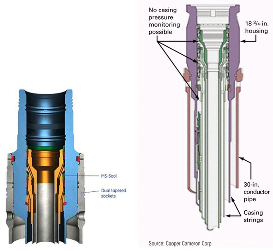
![[Note]](note.png) | Note The two most common external wellhead profiles are show in this diagram – the left figure shows a typical BHGE H-4 (Mandrel) profile and the left figure shows a typical Cameron (Hub) profile. Interface features are also identified –note especially the datum line– used for all height measurements. |
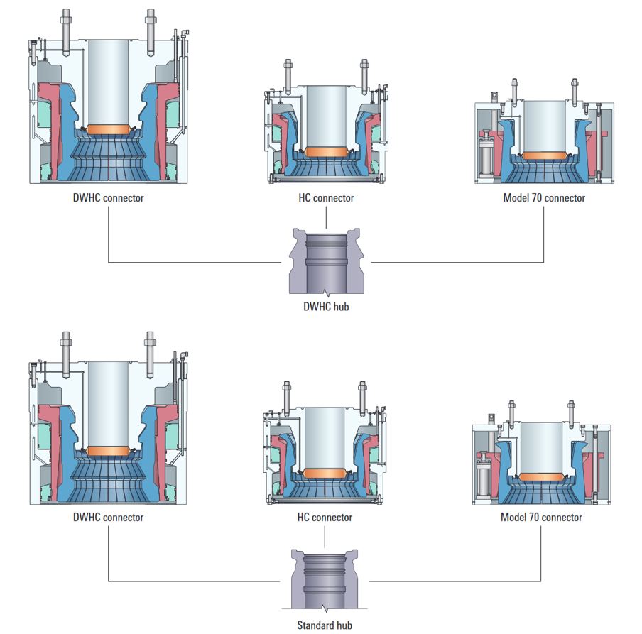
Deepwater profiles are now becoming more commonplace. These were developed for much higher bending and tension loads that can be experienced in deeper water depths. E.g. Cameron has developed the double hub style profile. This profile is unique in that either their new deepwater connector or their standard connector can latch onto it.
3.5 Tubing Spool Adapters
It is necessary that the Wellhead Connector on the BOP be compatible with the wellhead on the planned development well. Fortunately BOP wellhead connectors can be changed out relatively easily. Operators may therefore specify the wellhead type and profile of choice, taking into account compatibility with other existing wells or their preference for the well completion equipment. If an operator wishes to complete a well with a tree having a connector that is not compatible with the wellhead (allows to “de-correlate” the Wellhead supplier from the SPS supplier), a wellhead conversion can be installed. This wellhead conversion is called a Tubing Spool Adapter, and consists of a forged spool piece having a connector matching the existing wellhead on the bottom and a profile matching that of the tree’s connector on top. These conversions are sometimes referred to as tubing head adapters or Tubing Head Spool (most common name in TOTAL)
A Tubing Spool Adapter can also be used to provide a new wellhead seal surface if the existing one is damaged. This is not an uncommon occurrence with exploration wells that are ultimately completed and turned into production wells.
They are used to land the Tubing Hanger into, and this is often done for conventional style trees.
3.6 Typical Well Casing Programs
Depending on the soil conditions the well may be started with a large conductor such as 42 inch or 36 inch or, if a template is being used it may have a large sleeve pre-installed. Then a conventional 30 inch conductor is usually installed. Again depending on the anticipated loading this may have a 1 inch, 1-1/2 inch, 2 inch, or larger wall thickness.
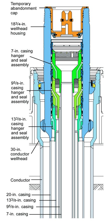
The well is then drilled ahead through this conductor. The 18-¾ inch high-pressure wellhead (housing) with 20 inch/18-¾ inch or similar sized Casing attached is then run through it, into the pre-drilled hole. Further holes are progressively drilled ahead and the appropriate sized Casing is then installed through the BOP and wellhead. These are selected from a variety of sizes depending on pressure containment, hole stability requirements etc. The following sizes are the most common; 20 inch, 18-¾ inch, 16-¾ inch, 13-3/8 inch, 10-¾ inch, 9-5/8 inch and 7 inch. The progressively smaller selected casings are suspended in the wellhead. Most wellheads can accommodate 3 or 4 hangers. (Figure 3.11, “A Typical Wellhead Stack-Up” illustrates an 18-3/4 inch wellhead with two Casing hangers installed). If more Casing is required, it can be suspended further down the well bore as a ‘Liner’.
Horizontal subsea Christmas trees, described elsewhere in this document, enable the wellhead system to have one less hanger than vertical trees normally demand of wellhead systems because the tubing hanger sits in the Horizontal Tree rather than the wellhead as in a conventional tree. It is still routine practice to have an extra hanger slot available in the wellhead ‘just in case’. Tubing Hanger adapter spools can be added above the wellhead to accommodate the Tubing Hanger and although rarely done, more Casing hangers if required.
Most of the Casing weight is suspended at the mud line by the wellhead. Some Casing strings are anchored deeper in the well. Later when the Production Tubing is installed, it is suspended either in the wellhead or Tubing Hanger adapter spool or in the tree above. Each method transfer the loads back to the wellhead.
During well production thermal and pressure effects on the tubulars can reverse the hanger loads and push up against the wellhead. Therefore lock down of the hangers is recommended for production wells. Some ‘Exploration’ wellheads do not apply the lockdown feature so as to facilitate dismantling and abandonment of the well and because this feature can sometimes be troublesome to install.

3.7 Wellhead Guide Structures
3.7.1 Guideline Drilling and Completions
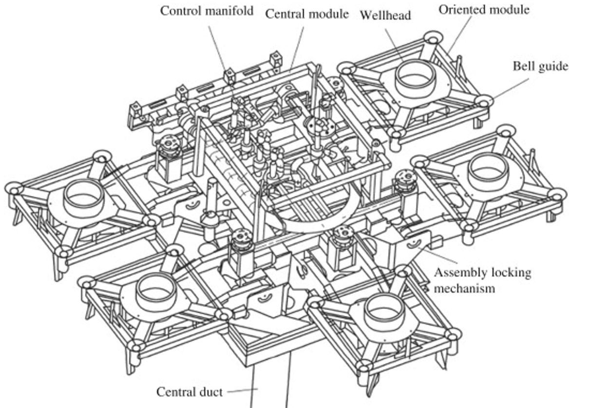
Most subsea wells employ the use of a permanent guide base (PGB) mounted to the low pressure conductor housing for guiding equipment (e.g. BOP) onto the wellhead, but also for alignment purpose (PGB heading is important for further jumper installation), support for jumper connector. The PGB is typically run with the conductor, or it can be subsea installed separately onto the conductor using a large funnel for guidance.
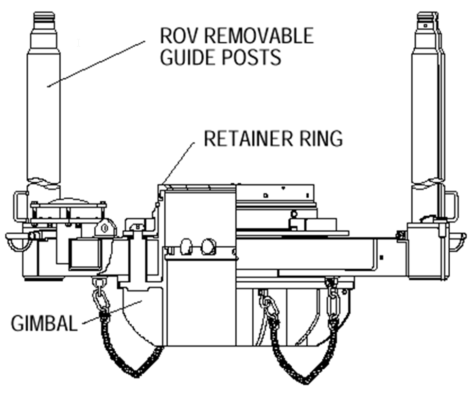
For guidance of the BOP onto the wellhead, it may use guideposts and wire rope guidelines, or more typically in deepwater applications, it may be a guidelineless style (incorporating upward facing funnel, or more typically accommodating BOP connector downward facing funnel). Where guideposts are used, these are normally designed to accommodate guide wires latched to the post tops. The post tops are generally designed to enable easy latching or unlatching of the guide wires and include a means of re-establishing new guide wires onto the post top. Virtually all guideposts will be on the API standard post spacing, four guideposts at 90º spacing, on a six-foot radius from the well center. This leads to the standard 101.82 inches between posts.
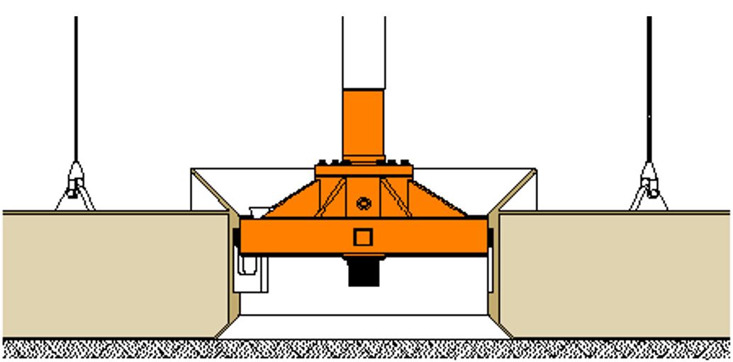
The nomenclature “permanent” is used to distinguish it from the “temporary” guide base (TGB), at one time traditionally used for starting the well, although modern rig equipment has made the TGB largely unnecessary. The TGB is typically a gravity-stabilized guide structure normally with a 42 - 46 inch diameter central hole. The TGB lies on bottom at the angle of the seabed and holds the guide wires in place to enable first the drill bit, and later the conductor to be easily guided through the central hole. The TGB typically also allows some conductor weight to be set down during cementing operations. The housing at the top of the conductor has the PGB attached to it, to take over the guidance function after the conductor has been secured. The term “temporary” in the name is misleading in that it is a permanent fixture to the well once deployed. Only the function is temporary.
PGBs normally incorporate level indicators that can be observed by camera when landing the first conductor in a new well. If the conductor is off true vertical by more than about one degree, the driller may decide to re-spud the well. It is recommended almost universally to do this if the well is off vertical by more than one degree. If not, key seating (wearing on one side) of the Casing and or BOP stack can occur seriously degrading the pressure integrity of the well and well control equipment.
PGBs can be designed to be retrievable while leaving the well intact for future use. This offers the advantage of not having to purchase a new guide base for every well.
If it is known beforehand that the well is to be a production or injection well, the guide base may incorporate guidance for well jumper or flowline connectors, or the connection itself with interconnecting pipework and an upward facing connector to the tree. This type of permanent guide base may be referred to as a completion guide base (CGB), or a flowbase or a Production Guide Base (most common wording used in TOTAL). Virtually all such guide bases are application specific designs.
3.8 Loads on Wellheads
Wellheads must be designed for high structural loads imposed during drilling, workover, or well completion operations. The wellhead must support the weight of the BOP, drilling riser loads (weight, sea currents, etc.), Casing weight and forces imposed by internal pressure. In general, wellheads are of such robust construction that, as far as external loads are concerned, they are rarely the weak point of the wellhead system. The 15M wellheads can generally sustain greater external loads than the 10M wellheads. For deep water and other special applications, manufacturers must engineer the wellhead equipment to meet the specified load requirements. A heavy duty deepwater wellhead with a Super Heavy Duty connector engaging two profiles instead of the one for more strength is shown in Figure 3.12, “neSubsea Model 70, High Capability (HC) and Deepwater (DWHC) Wellhead Connectors on Standard and Deepwater HC Wellhead Hubs, Connector Versatility and Hub Interconnectability”.
To improve the transfer of loads from the wellhead to the low-pressure conductor housing and reduce fatigue stresses and fretting at critical wellhead interfaces, a rigid lockdown system may be employed. This mechanism locks the wellhead housing securely into the low-pressure conductor housing. It may be engaged automatically with the installation of the wellhead (passive), or it may require an externally applied preload (active).
3.9 Subsea Wellhead Materials
The following is a list of typical materials used for main components in a Subsea Wellhead system.
Table 3.1 - Subsea Wellhead system material list
COMPONENT | MATERIAL |
Low Pressure Conductor Housing | AISI 8630 Modified. |
Conductor Pipe | API 5L X52 |
18 3/4 inch Wellhead Housing | AISI 8630 Modified, 80 Ksi. Yield |
Wellhead Seal Area | Inconel 625 Overlay |
20 inch Casing Extension, | API 5L X52 |
Wellhead Lock Ring | AISI 4140/4145, 105 Ksi. Yield |
Casing Hangers | AISI 8630 Modified, 80 Ksi. Yield |
Pack-Off Seal Elements | AISI 1010 or 1015 |
Pack-Off Bodies | AISI 4140, 75 Ksi. Yield |
Pack-Off Split Rings | 17-4 PH, 100 Ksi. Yield |
3.10 Description of Typical Subsea Wellhead System Components
The following are features that should generally be expected in wellhead equipment:
The ability to test all the seals and locking arrangements.
Protection for all permanent seals during running and the seals are remotely energized after landing.
The ability to clean component seal surfaces after cementing operations and prior to setting the pack off seals.
The Casing hangers have ability to be locked in place.
The flow path for cuttings and cement returns without excessive build-up of pressure, blockage or reduction in velocity through the flow-by holes and slots.
The use of a minimum number of seals and components installed subsea.
The primary metal-to-metal seals with elastomeric secondary system for all permanently installed seals.
Weld overlay surfaces with a nickel-based alloy (Inconel 625) at the wellhead's gasket seal surface.
Reliable and robust suite of versatile running tools.
For the purposes of this discussion, a wellhead system consisting of the following components will be considered:
3.10.1 30 inch Conductor Housing Joint.
The 30-inch conductor-housing joint provides the structural foundation for the wellhead system. The outer diameter of the housing is fitted with a keyway and a shoulder to provide orientation of the PGB which in turn orientates the BOP and the Tubing Hanger, and later the tree. The joint generally consists of a 30 inch conductor housing welded onto a 30 inch conductor pipe. A proprietary, mechanical, pin connector is fabricated onto the bottom end of the 30-inch conductor for connection to the next conductor joint below. The overall length of the joint is approximately 40 - 45 feet. Ease of road and sea transportation is a consideration when specifying the overall length. The 30-inch conductor will normally have large landing pad eyes for handling and hang off purposes welded to it near the housing. The string is suspended below the pad eyes through the rotary table while the running tool is made up to it. The padeyes are then cut or burnt off and the Casing runs to the seabed.
A 30-inch conductor housing should normally provide the following features:
An internal profile locking facility for the 30-inch conductor housing running tool and an external locking profile for the PGB.
Side outlet holes for cement returns.
Control of the elevation, concentricity, and vertical alignment of the 18-3/4-inch wellhead housing by the load shoulder and locking mechanism incorporated with the internal profile.
Unrestricted passage of a 26-inch drill bit.
Available working pressure of 2000 psi (135 bar).
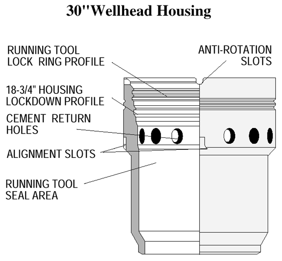
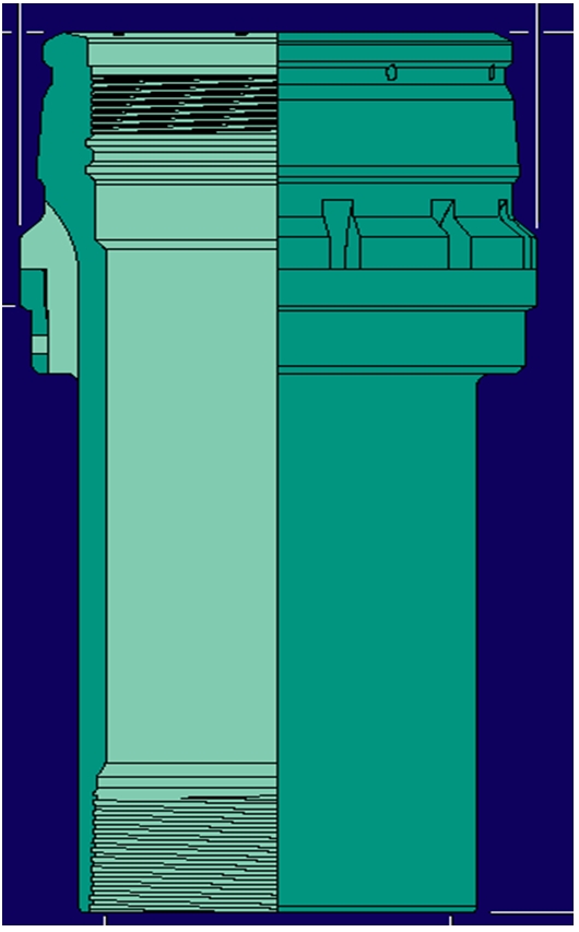
3.10.2 18-3/4 inch Wellhead Housing Joint.
The 18-3/4 inch wellhead housing joint serves as the suspension head for the surface Casing string and provides a mechanical connection and sealing preparation for the BOP stack and tree. It also provides landing, locking, and sealing preparations for the subsequently run Casing hangers. The 18-3/4 inch wellhead housing joint generally consists of an 18-3/4 inch high pressure housing welded to a 20 OD pipe (typically 0.625 inches wall thickness). A 20 inch pin connector is welded to the lower end of the Casing joint.
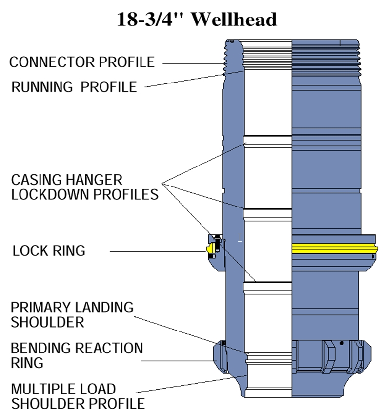
An 18-3/4 inch wellhead housing should generally provide the following features:
Positive mechanical lockdown mechanism into the 30 inch conductor housing.
Provision for the flow of drill cuttings and cement returns between the 18-3/4 inch wellhead and the 30-inch conductor housing.
Control of the elevation and concentricity of the Casing hangers and the Tubing Hanger.
Seal surfaces appropriate for the sealing systems associated with the test and running tools.
Transfer loads from the hangers and bending loads from the BOP and riser into the 30 inch conductor housing. This can be achieved by ensuring two point contact between the 30 inch conductor housing and the 18-¾ inch wellhead housing.
Allow passage of 17-1/2 inch drill bit.
Incorporates an external Wellhead Connector profile to suit the XT connector, BOP connector or Tubing Head Spool connector.
A wellhead gasket seal preparation for metal-to-metal sealing between the wellhead and the connector, inlaid with nickel based alloy Inconel 625.
Suitable working pressure of 10,000 or 15,000 psi
A variety of profiles exist in the market today. There are two primary profiles, licensed by two different manufacturers. All manufacturers produce each other’s profiles through cooperative agreements and license arrangements. The two most common profiles are currently being further developed for deep water requirements demanding higher capacities.
Figure 3.12 - neSubsea Model 70, High Capability (HC) and Deepwater (DWHC) Wellhead Connectors on Standard and Deepwater HC Wellhead Hubs, Connector Versatility and Hub Interconnectability
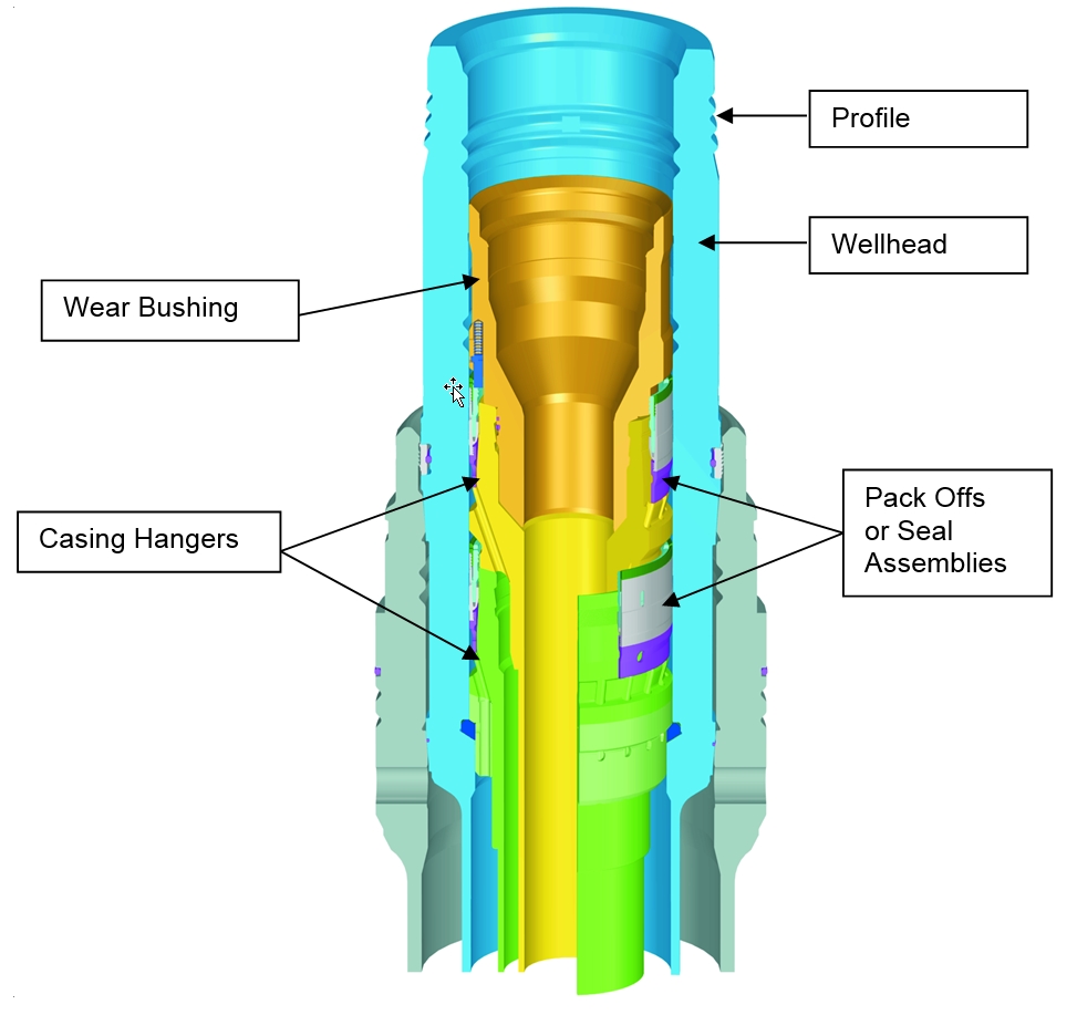
3.10.3 The Casing Hangers
The Casing hangers centralize and suspend the Casing strings inside the 18 3/4 inch wellhead housing. They also provide seal surfaces for the pack off assembly to isolate the Casing annuli. The Casing hangers are normally supplied with a Casing pup joint pre-installed. The Casing pup usually terminates with a pin connection.
Casing hangers should generally provide the following additional features:
Two-point centralization in the 18-3/4 inch wellhead housing.
Sufficient flow-by area to permit flow of drilling mud, cuttings, and cement.
Allows passage of drill bits for the next successive Casing size.
Interfaces with a variety of running tools – such as drill pipe tool, full bore tool, or single trip tool.
Suitable working pressure of 10,000 or 15,000 psi.
Suspend a sufficient working load – usually at least 1,000,000 lbs capacity.
3.10.4 Pack-Off (Seal) Assembly.
Pack-offs or Annulus Seal Assemblies (ASA) in the wellhead seal the Annulus between casings. Older Pack-Off designs used elastomer seals. Newer designs employ metal to metal seals. These are, in some cases, actually composite metal and elastomeric seals designed so that the elastomer provides an initial seal that, with deformation, causes the metal seal to be forced into place or ‘energized’. The elastomer serves as a back-up seal.
The pack off or seal assembly should generally provide the following features:
The necessary seals and components to ensure that the seal is set, energized, tested and if required, retrieved in a single down hole trip.
Seals are protected during running phase.
Single trip tool runs Casing hanger and pack off assembly as a unit.
Complete seal assembly can be retrieved using single trip tool or a pack off retrieval tool.
An effective seal for continuous or intermittent Annulus pressure.
Bi-directional metal-to-metal seal with elastomeric backup seals to pack off the Casing hanger to 18 3/4 inch wellhead housing Annulus.
Suitable working pressure of 10,000 or 15,000 psi.
3.11 Wellhead Running Tools
Running tools are required to install, test and retrieve the wellhead system components. These tools are supplied by the wellhead manufacturer as part of the wellhead system, and are usually available on a rental basis. One aspect of wellhead system design is to design the running sequence and tools so as to minimize the number of trips required. This becomes more important in deep water where rig rates are high and trips take more time.
The tools should be of robust design, debris tolerant and capable of giving strong easily detected signals of correct function that can be observed at the drill floor.
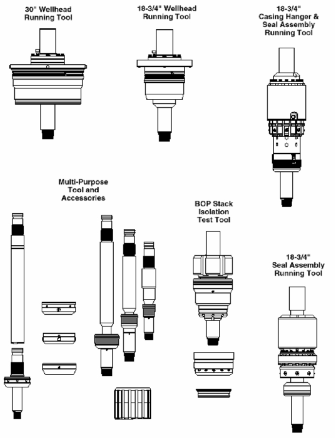
3.11.1 Bore Protector
The bore protector is used to protect the Casing hanger sealing surfaces inside the 18 3/4 inch wellhead housing during the newt drilling section only (after it is the wear bushing which is used). The wellhead housing can usually be deployed with the bore protector installed. Additionally, most systems have tools designed that do not transfer pressure end load into the protector and therefore allow the BOP stack to be pressure tested without retrieving the bore protector. The bore protector is normally mechanically held in place by shear pins or O-ring friction.
3.11.2 Wear Bushing.
The wear bushing protects the bore of the pack-offs and Casing hangers from mechanical wear associated with drilling activities subsequent to the setting of the intermediate Casing string. It is deployed and retrieved on drill pipe and set using a wear bushing running and retrieval tool. These are often used for several functions and called multi-purpose or multi-utility tools. The wear bushings are normally designed to allow BOP testing to be conducted without retrieving the bushing.
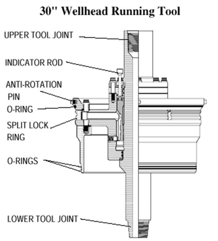
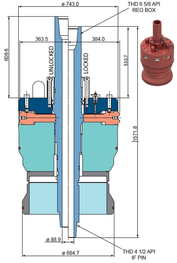
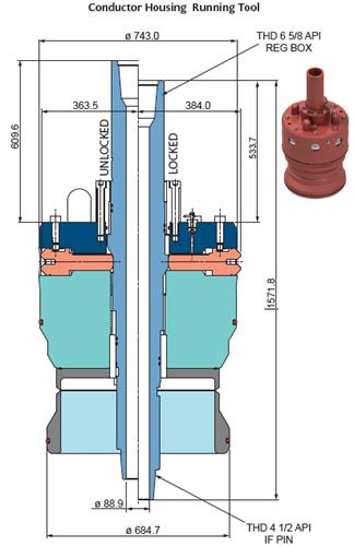
3.11.3 30-Inch Conductor Housing Running Tool.
The 30 inch conductor housing running tool is used to deploy the 30 inch conductor string and housing. Typical features of this tool are:
Locks into the profile of the 30 inch conductor housing.
Seals inside the 30 inch conductor housing below the flow-by ports
Visual position indicator provided.
Anti-rotation feature.
Right hand rotation of the running string releases the tool. This is often a hydraulic function in deeper waters.
6 5/8 inch API Regular box up by 4 1/2 inch API Internally Flush (NC50) pin down.
Valves to allow filling of the string with seawater and then closed.
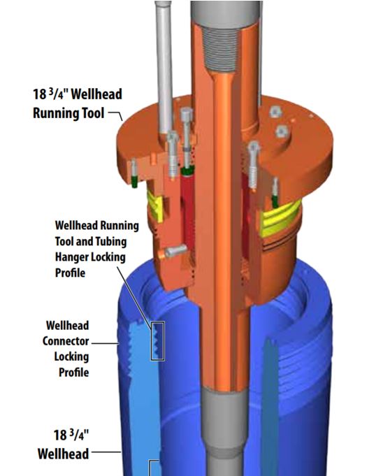
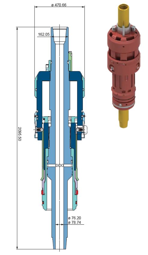
3.11.4 18 3/4 inch Housing Running Tool.
The 18 3/4 inch housing running tool runs the high-pressure wellhead housing. It typically includes the following features:
Locks into the upper groove inside the wellhead bore.
Has visual position indicator.
Right hand rotation of the running string to release. This is often a hydraulic function in deeper waters.
Provides a mean to activate the lockdown mechanism of the wellhead into the LP housing (generally by hydraulic actuation for DW applications).
6 5/8 inch API regular box up by 4 1/2 inch API Internally Flush (NC50) box down.
Anti-rotation pins to prevent free spinning of the tool inside the housing.
Valves to allow filling of the string with seawater and then closed.
3.11.5 Bore Protector Running and Retrieval Tool.
A Bore Protector Running and Retrieval Tool is typically used for running and retrieving all of the 18-3/4 inch bore protectors and wear bushings. It can also be used as a test tool with wear bushings in place or as a washout tool if need be. The tool typically has a 4-1/2 inch API Internally Flush (NC50) box up by 4-1/2 inch API Internally Flush (NC50) pin down.
3.11.6 Single-Trip Tool
Most wellhead systems have a single trip tool available which is used to run, set, and test the Casing hangers with its pack off in a single trip. After the Casing is cemented in place, the tool hydraulically sets the pack off. Most tools are designed so that if the pack off should fail to set properly, the tool will retrieve it. The tool generally has a 6-5/8 inch reg. box up by 4 1/2 inch API I.F. pin down.
3.11.7 Pack-Off Assembly Running Tool
The Pack-Off Assembly Running Tool is primarily used to run, set, or retrieve the pack off independently of the Casing hanger. It will typically enable testing of the pack off in the same running trip. The tool typically has a 4-1/2 inch API Internally Flush (NC50) inch box up by 4-1/2 inch API IF (NC 50) box down.
3.11.8 Drill Pipe Casing Hanger Running Tool.
The Casing hanger running tool runs the Casing hanger without its Pack-Off on drill pipe. Running the Casing hanger and pack off this way is a two-trip operation and in deeper waters is generally avoided.
3.11.9 Full Bore Casing Hanger Running Tool.
The Casing hanger running tool runs the Casing hanger without its Pack-Off on Casing. Running the Casing hanger and pack off this way is a two-trip operation and in deeper waters is generally avoided.
3.11.10 BOP Test Tool.
The BOP test tool is used to test the BOP stack without subjecting the wellhead components below it to the BOP test pressure. The tool is deployed on drill pipe and seals inside the wellhead housing bore.
3.11.11 Emergency Drill Pipe Hang-Off Tool.
The emergency drill pipe hang off tool is used to suspend drill pipe in the wellhead during suspended drilling situations. Drill pipe weight is transferred into the wear bushing. The configuration of the tool is unique to the particular BOP stack involved in the field development.
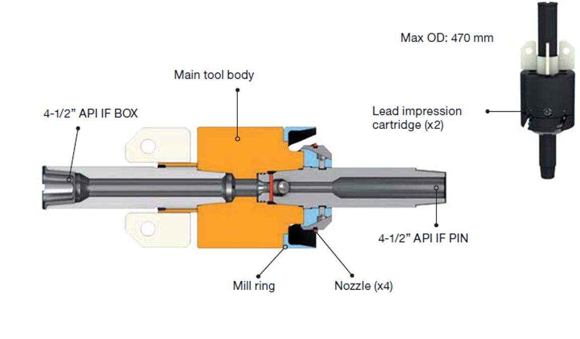
3.11.12 Mill and Flush and Lead Impression Tool.
The mill and flush tool is primarily used to clean out the annular area behind the Casing hanger neck before the installation of the pack off assembly.
Lead impression blocks can be provided to enable the elevation of the Casing hanger to be verified prior to running the pack off or in case of the unavailability to set the Pack-Off.
3.11.13 Emergency Seal Assembly.
The emergency seal assembly is used when the Casing hanger is set high. Height adjustment is built into the design of the emergency seal assembly enabling it to pack off on the high set, Casing hanger. It can then still provide a landing shoulder for the subsequent run Casing hanger or seal surface for the Horizontal Tree stinger at the correct elevation.
3.12 Typical Subsea Wellhead Installation Procedures
Run 30 inch conductor string into open hole with 30 inch suspension joint attached to the guidance cone
Once landed and set to the correct vertical elevation, cement 30 inch conductor in place according to operator procedures
Rotate the drill pipe and pull to release running tool. Pull back to surface.
Drill the next hole to TD and run the 20-inch Casing.
Note
When the conductor string is jetted into place, the running tool may incorporate a drill-ahead tool, allowing the hole for the 20” Casing to be drilled without retrieving the conductor housing running tool, thus saving a trip and cementation operation as in case of jetting no cementation operation is performed.
Attach the 18 ¾ inch wellhead body to the 20-inch Casing. Install the bore protector in the wellhead (if not installed at the factory). Run cement stinger into wellhead housing sitting on rotary table and make up the wellhead body to the running tool. Make up running tool to wellhead.
Run the wellhead body assembly into the suspension joint. Cement.
Release the running string from the wellhead by rotation and pull back to surface.
Place the drilling BOP across the spider beams over the moon pool. Make up the hydraulic umbilicals and check all the functions.
Run the BOP on Marine Riser. Lock BOP connector onto 18 ¾ inch wellhead. Rig up diverter with choke and kill lines.
Make up the isolation test tool onto drill pipe string run into the Marine Riser. Run into the wellhead. Test the BOP stack then retrieve the test tool.
Drill the hole for the 13-3/8 inch Casing. Pull back the string and make it up to the bore protector retrieval tool. Run in and retrieve the bore protector.
Run in the 13-3/8 inch Casing string with attached cementing equipment.
Make up the 13-3/8 inch Casing hanger and the pack off to the single trip tool and make this assembly up to the Casing string, run in the hole with the drill string and Casing.
Land the hanger into the 18 ¾ inch wellhead. Slack off the weight and cement the string into place. Activate the pack off setting mode of the tool
Slack off the string weight and close the BOP pipe rams.
Build up pressure above the tool to set and test the pack off. Open the pipe rams, release the tool from the pack off and then pull it back to the surface.
Run in the 13-3/8 inch bore protector on the bore protector running tool. Land and lock into the wellhead. Release the tool and pull back to the surface.
Repeat the above steps to run the next Casing strings.
Start next functions for well – (e.g. Temporary abandonment, permanent abandonment, completion, etc.).


