4 Subsea Christmas Trees
4.1 Functions of Subsea Trees
![[Tip]](tip.png) | Tip Click these links below for access to 3D resources: |
A subsea Christmas tree is basically a stack of valves connected by flowloops (common wording in TOTAL) installed on a Subsea Wellhead to provide a controllable interface between the well and the production facilities.
Some specific functions of a subsea Christmas tree include the following:
Sealing the wellhead from the environment by means of the tree connector.
Providing two testable barriers between the production fluid and the environment.
Providing a controlled flow path from the Production Tubing, through the tree to the production flow line. Well flow control can be provided by means of tree valves and/or a tree-mounted choke.
Providing vertical access to the well bore via the tree cap (and swab valve in the case of the vertical tree).
Providing access to the Annulus for well control, pressure monitoring, gas lift, etc.
Providing a hydraulic interface for the down hole safety valve and intelligent well completion valves and Tubing Isolation Valves (TIV).
Providing an electrical interface for down hole instrumentation, electric submersible pumps, etc.
Providing structural support for flow line or jumpers and control umbilical interface.
Provide a snag resistant or overtrawlable structure (depending on area and water depth) to prevent damage of the wellhead / tree due to snagging of fishing gear etc.
4.2 Types of Subsea Trees
4.2.1 Dualbore Vertical Tree on wellhead
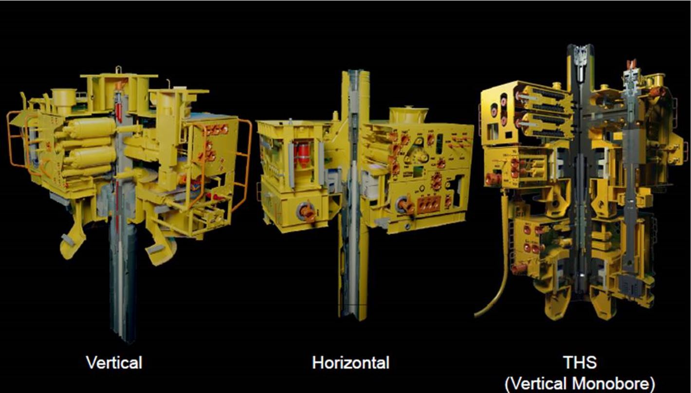
Until recently, most subsea trees were so-called “dual bore” type trees. A typical dual bore vertical tree is illustrated in Figure 4.5, “Example of vertical tree (Aker Solution – KAOMBO PVXT)”. These trees have a production and Annulus bore passing vertically through the tree body with production and Annulus master valves and swab valves oriented vertically in the main block of the tree. They are designed to allow vertical access to the main production bore and to the Annulus bore during installation and workover operations. When a dual bore subsea Christmas tree is connected to a Subsea Wellhead it must interface with the tubing hanger previously installed in the wellhead. The Tubing Hanger and tree must be correctly orientated so they mate properly with one another and the production and Annulus bores as well as associated hydraulic and electrical couplers are properly aligned and sealed. Alignment of the Tubing Hanger in the wellhead is generally accomplished by alignment of the BOP with the PGB, alignment of the Tubing Hanger with the BOP, and subsequently alignment of the tree with the PGB. Alignment of the Tubing Hanger with the BOP is achieved by interaction of a pin mounted in the BOP, or a pre-machined vertical orientation slot in the BOP connector upper body with a helix in the Tubing Hanger landing string, . The reaction between the pin and the helix causes the Tubing Hanger assembly to rotate into the correct position. Alternatively, the Tubing Hanger is rotated until the alignment slot lines up with a spring-loaded alignment key on the running tool.
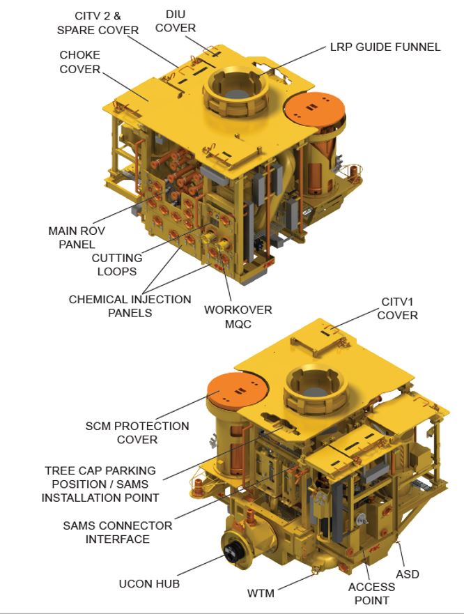
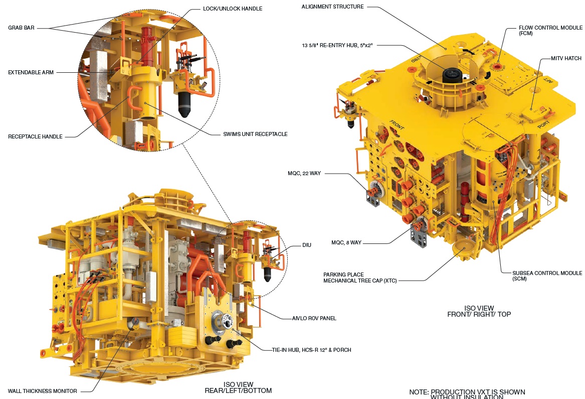
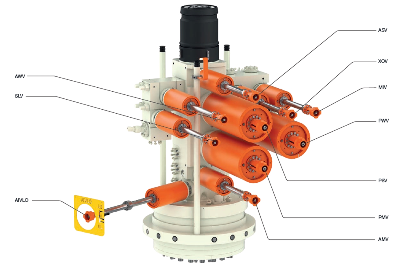
Table 4.1 - Valves body of vertical tree (Aker Solution – KAOMBO PVXT)
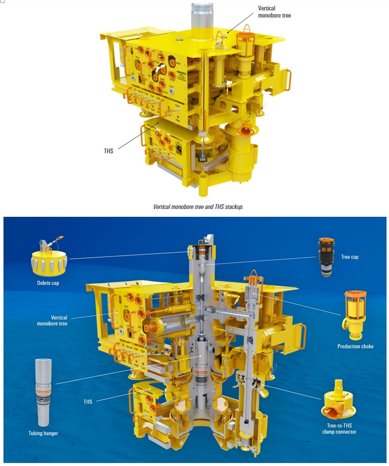
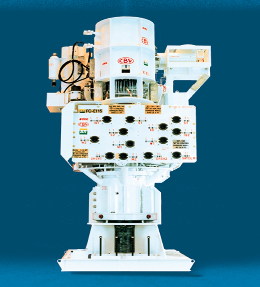
4.2.2 Monobore Vertical XT on Tubing Head Spool
A typical mono bore tree is similar to a conventional dual bore tree but differs in that it utilizes a simpler riser system to install the tree and Tubing Hanger. Main difference is no mechanical/vertical access to the Annulus bore. Monobore vertical tree can be installed either on THS or directly on Wellhead (like Proserv Vertical Concentric Monobore Subsea Tree). The picture below presents Monobore installed on
THS. Additionally simpler styles of monobore trees exist which are generally used on mud line completions in shallow water.
When producing a well, the Annulus between the Production Tubing and the well Casing must be accessible to relieve thermally induced pressure build up. In order to accomplish this, Tubing Hanger and tree systems must enable access to the Annulus under the Tubing Hanger. Vertical trees as opposed to horizontal XT (except the basic mudline style trees) utilize a port through the Tubing Hanger. This port, as well as the production bore, must be closed before removing the BOP or the Subsea Tree.
On a conventional style tree, the Annulus port is typically sealed with a wire line plug run and retrieved through a multi-bore completion riser or a riser with a diverter mechanism. This riser is generally expensive and dedicated to the tree system. Refer to descriptions of riser systems elsewhere in this document for detailed descriptions.
In the mono bore tree system the Tubing Hanger is run on workover riser (typically faster to run than dual bore completion risers) and the Annulus is accessed through a hose bundle, which may be incorporated into the workover umbilical. Opening and closing of the Annulus is accomplished by means of a “shiftable” plug or valve in the Annulus bore of the Tubing Hanger. The disadvantage to this, as compared to the dual bore system, is the requirement for moving parts within the Tubing Hanger that must be left subsea for the life of the completion.
Some designs incorporate a second plug or valve, ported in series with the primary plug, which can be actuated as a backup to close the Annulus if more redundancy is desired.
As the Tubing Hanger Annulus bore has its own closure device, the mono bore tree obviates the need for a true vertical Annulus bore through the tree.
An enhanced version of the dual-bore tree combines the benefits of dual bore and mono bore trees. The tree itself has dual bores as before, but the Tubing Hanger has its own closure devices as per the mono bore tree. The tree is therefore run on a mono-bore (e.g.; drill pipe) riser. In the event of a Tubing Hanger Annulus valve failure, the Annulus bore of the tree can be accessed via a bore selecting mechanism on the running string, e.g. in the EDP, in order to run a shifting tool or contingency plug into the Tubing Hanger Annulus bore.
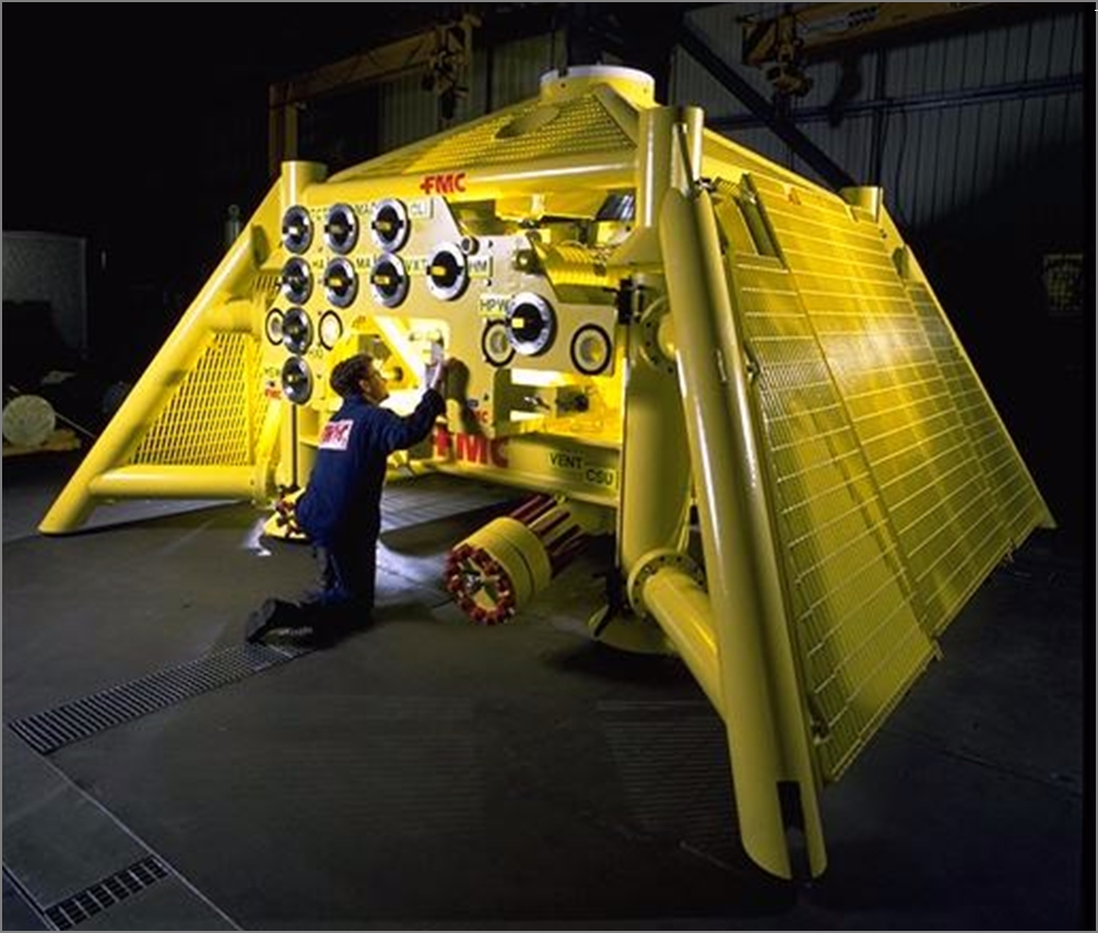
4.2.3 Horizontal Tree on wellhead
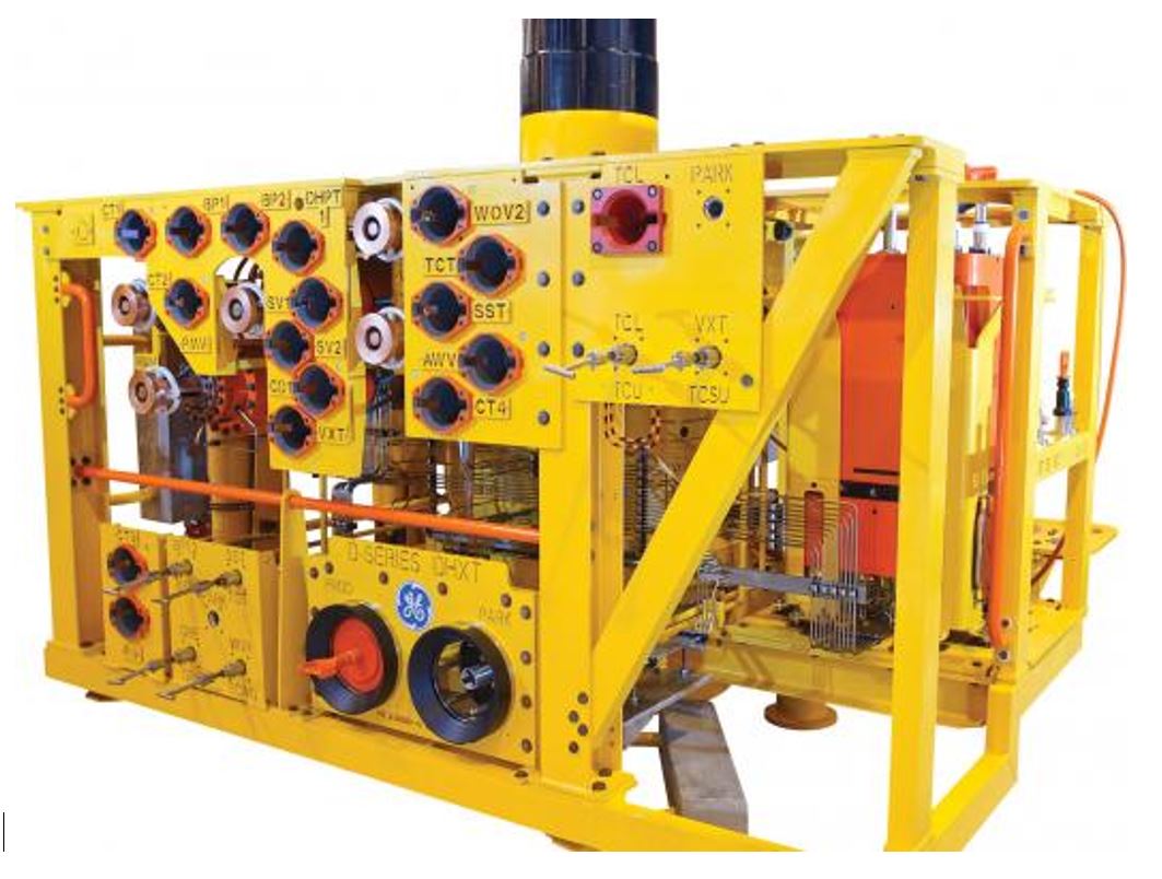
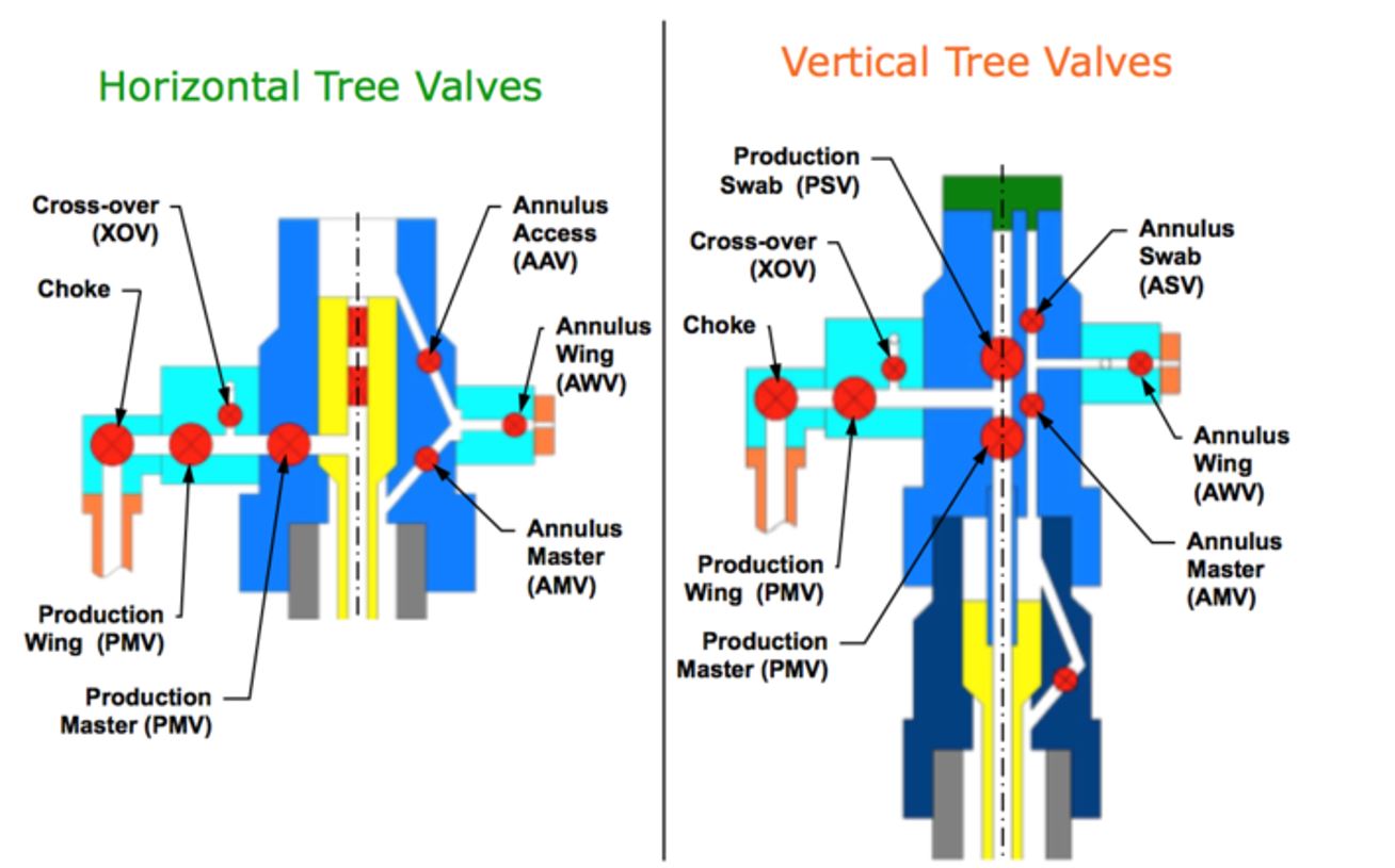
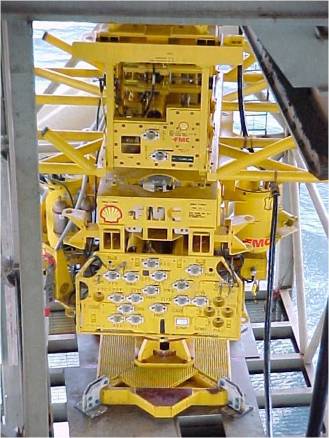
Another type of subsea Christmas tree that has gained popularity since its introduction in the early 1990s is the “horizontal” tree. A typical horizontal subsea trees are illustrated in Figures below. Its most obvious distinction from the Dual Bore Tree is that the production and Annulus bores branch horizontally out of the side of the tree body and the valves are oriented on a horizontal axis. The Horizontal Tree has no production or Annulus swab valves. Access to the well bore is gained by removing the internal tree cap, or a wireline plug within the internal tree cap, and a wireline plug in the Tubing Hanger. The horizontal subsea Christmas tree is sometimes referred to as a “side valve tree” or SpoolTree™.
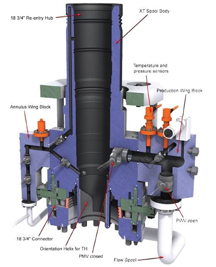
Other distinguishing features of the Horizontal Tree, in addition to the valve arrangement from which it gets its name, are: 1) the Tubing Hanger is installed in the tree itself, rather than in the wellhead and 2) the top of the tree is designed so the BOP may be landed onto the tree. This arrangement allows the tubing string to be recovered without first retrieving the tree.
Horizontal Tree technology was conceived and developed to run and retrieve well bore tubing through an installed tree providing a simple and efficient work-over capability. Originally, this type of technology seemed ideally suited for Electric Submersible Pump (ESP) applications, where frequent pump maintenance or replacement may be required. Well interventions were most commonly caused by the need to repair downhole problems as opposed to Subsea Tree equipment problems.
The concept was extended to include standard production and injection wells in the belief that horizontal technology offered much greater benefit over conventional technology, at least in some applications.
The benefits and drawbacks of both horizontal and conventional tree technologies have been the subject of many debates for several years. The newer Horizontal Tree technology has been shown to have significant merit in order to have acquired at least 50 % of the market in less than six years. It is probable that both completion technologies will have a vital part to play in future oil and gas developments and the possibility of a winner for all applications is unlikely.
4.2.4 Advantages of Horizontal Trees
Tubing recovery is simplified. The ability to perform tubing work-over and some drill-through operations without the need to recover the Subsea Tree and disturb the associated production flowline/controls connection is beneficial. This is particularly attractive for wells with planned or scheduled tubing work-over intervention or complex down-hole completions with the higher probabilities for down-hole failures requiring rig intervention.
The HXT is suitable for tubing up to 7” OD whereas the vertical (either dual or monobore type) tree is generally limited to 5-1/2” OD. The larger bore can also accommodate a larger number of down-hole hydraulic control lines, chemical lines and electrical transducer penetrations with the capability to provide full bore Annulus circulation or injection.
The large bores possible with this system are consistent with the usual objective to reduce the number of wells. However, reliability may be compromised by a more complex completion.
The ability to use standard, drilling BOP stacks for installation and work-over. All the completion operations except for running the Subsea Tree and debris cap are performed through the drilling BOP stack. This eliminates the need for a dedicated open water completion riser system.
All completion work is carried out through or within the protection of a BOP stack.
The ability to use single string tubing or Casing as an installation and completion riser allows a cheaper riser to be configured than a conventional dual bore riser. The BOP stack’s choke and kill lines are used to circulate the Annulus or riser fluids prior to disconnection and recovery of the riser system. The Production Tubing Annulus access bypasses the Tubing Hanger and uses metal sealing valves for Annulus isolation. This provides maximum space through the Tubing Hanger body for big bore completions.
Subsea Tree installation or recovery is greatly simplified by using drill pipe instead of a dedicated riser system.
The Subsea Tree provides an integral and precise, passive Tubing Hanger orientation system with no requirement for BOP modifications, interaction or datum’s.
The Horizontal Tree is arguable more tolerant of damaged sealing surfaces in the wellhead system. Therefore there are greater probabilities for successful installation on existing and perhaps old exploratory wellheads of uncertain integrity. The tree provides new, exact and retrievable Tubing Hanger landing, locking, orientation and sealing profiles, not dependent on the condition of wellhead internal profiles although the Horizontal tree stab does seal to the uppermost Casing hanger in the well. The tree readily adapts to different wellheads from different vendors.
The Tubing Hanger-to-Subsea Tree interface is tested and verified at the time of landing the Tubing Hanger in the tree while the BOP stack is still in place. Should problems arise, this offers the possibility for recovering the Tubing Hanger and taking immediate remedial action without tripping the stack. A conventional tree-to-wellhead/Tubing Hanger interface cannot be verified until after the BOP stack has been recovered and the tree installed. A failure to interface properly can have serious time/cost implications, especially if the Tubing Hanger is damaged or not in the correct orientation when the tree lands.
Subsea Tree single-piece spool body construction provides the maximum tree spool strength characteristics and reliability with minimum failure modes. These are considered to be stronger than conventional trees.
Horizontal trees are compact, have a low profile and an excellent strength-to-weight ratio.
Subsea component ‘building blocks’ can be arranged into many different tree layouts. This has given considerable flexibility to Horizontal Tree configuration and improved the opportunity of mass produced tree equipment by allowing the flexibility to manufacturers. Tree internals can be standardized while external characteristics can be varied or moved to suit the application.
4.2.5 Disadvantages of Horizontal Trees
The tubing must be pulled first before retrieving the tree. Horizontal Tree recovery requires that the down-hole completion is recovered first, with the associated well killing operations through the BOP stack. Rationalization of this disadvantage is based on intervention data, that suggests that Subsea Tree failures, requiring the tree to be recovered, are a low percentage of all major failures requiring intervention. By far, the greatest percentage of failures, relate to the failure of down-hole equipment, such as safety valves, gravel packs, etc. This suggests that intervention savings are actually likely to be accrued due to the use of Horizontal Tree technology, as down-hole work-over frequency is much greater than the probability of tree recovery.
A drill-and-complete scenario for Horizontal Trees currently requires two BOP trips. (Run the BOP stack; drill well; recover BOP stack; run tree; re-run BOP stack; finish complete; recover BOP stack). This disadvantage can be mitigated by batch drilling / completing.
A Horizontal Tree does not include master and/or swab valves in the vertical bore of the tree to provide first-line barrier protection to the environment. It relies on a wireline plug to provide the first line barrier protection. Care must be taken to ensure that the critical wireline plug sealing surfaces in the Tubing Hanger and tree cap are not damaged during wireline operations.
The Subsea Tree must be designed to withstand the loadings associated with a deepwater BOP stack and riser system. The BOP and Marine Riser loads imparted to the wellhead are higher than for a conventional system as the loads are applied at the top of the tree during the completion phase.
The bore of the Subsea Tree may be exposed to a very harsh drilling riser environment requiring special provisions for bore protection and bore cleaning in order to ensure successful tubing hanger installation and valve reliability.
Tubing Hanger installation requires the use of a sophisticated BOP subsea intervention tree and landing string system in order to provide for safe flow testing, wireline and coil tubing intervention and emergency disconnect scenarios. This adds complexity and time to the Tubing Hanger and down-hole completion, installation process. The Tubing Hanger installation requires simultaneous control of the Tubing Hanger running tool, Subsea Intervention Tree and landing string system, BOP and subsea tree’s work-over functions. This involves up to four umbilicals and their control panels.
The Tubing Hanger hydraulic and electrical penetrations exit through the side of the subsea tree’s spool body. Control of hydraulic functions and monitoring of electrical functions is typically not provided although available, during installation of the Tubing Hanger system.
The side outlet penetrations for control and electrical functions are additional leak paths in the primary tree bore during drilling and completion operations
ROV’s must be used to connect/disconnect work-over controls between the BOP and Subsea Tree.
A landing string leak or failure during well test or well clean up can divert hydrocarbons to the rig floor, burst the Marine Riser, or evacuate the Marine Riser allowing it to collapse under hydrostatic pressure.
4.2.6 Advantages of Vertical Dual and Mono Bore Trees
Only one BOP trip is required in a drill-and-complete scenario. In addition, no temporary well abandonment plug is required between the BOP stack recovery and the tree installation as the Tubing Hanger serves that purpose.
The Subsea Tree can be recovered without having to recover the Tubing Hanger and down-hole completion because the tubing hanger lands in the wellhead and not in the Subsea Tree.
The Subsea Tree is not required to withstand high loads associated with a Drilling BOP stack.
In some designs, in particular with direct hydraulic workover control systems, workover control connections are made between stab rings mounted on the Tree Mandrel and the LRP connector, in which case no ROV is required.
4.2.7 Disadvantages of Vertical Dual and Mono Bore Trees
The wellhead bore sets the Tubing Hanger outside diameter, leaving only a limited area for downhole access. This restricts the largest possible production bore size when including all the other down-hole penetrations required. Particularly the Annulus bore that provides a circulation path that can also be sealed with a wireline plug. The 2” Annulus bore is selected for the minimum reliable wireline plug size and exceeds the flow requirements. The available space is even more severely limited when considering a concentric Tubing Hanger design or for the need for Annulus injection or downhole gas lift capabilities.
If deepwater wells tend toward intelligent completions and/or simultaneous production from different reservoirs, conventional tree technology is inherently limited by the restricted space inside a wellhead. An alternative would be to use the hybrid tree, which lands a conventional tree on top of a Horizontal Tree, for these applications.
The Subsea Tree must be recovered in order to perform a tubing work-over. This disturbs the Production Flowline and umbilical connections. This creates new opportunities for damage to other hardware that is often not easily recovered.
A Monobore riser with a remotely operated selector crossover mechanism at its base, in order to provide wireline access to the Annulus can be unreliable. Alternatively, crossover mechanisms which are manually operated (swapping of a joint etc.) require the string to be retrieved resulting in additional rig time.
The Subsea Tree is typically installed on the dedicated workover riser and wireline BOP intervention system in order to provide for flow testing, wireline and coil tubing operations, and emergency disconnect. This adds complexity and time to the installation process.
The integrity of the wellhead interface is an issue. Damaged seal surfaces in the wellhead are not readily replaced and require an expensive Tubing Hanger adapter.
No industry standard interface exists and the formalities of exchanging design information with a competitor and taking responsibility for its performance can be difficult.
The tubing hanger’s orientation system is very complex with very significant orientation tolerances in the system. It relies on accurate setup and active interaction with the BOP stack. The interface between the Tubing Hanger and the Subsea Tree cannot be tested until the BOP stack has been recovered and the tree installed.
A leak or failure of the riser system during well test or clean-up will produce hydrocarbons to the environment. If the failure occurs near the surface safety issues arise.
4.2.8 Other Types of Trees
There are other specialized variations of subsea trees as well. These include Through-Bore-Tree trees designed for use with special “through flowline” (Through-Bore-Tree) workover equipment; “Single-Bore™” or “mono-bore” trees with a vertical production bore and a side valve for Annulus access; “through-bore” trees with the Tubing Hanger in the tree body and “concentric” trees (e.g. Proserv Vertical Concentric Monobore Subsea Tree), used with a concentric Tubing Hanger and not requiring orientation between the tree and Tubing Hanger.
4.3 Components of a Typical Subsea Tree
| Tip Click these links below for access to 3D resources: |
The subsea Christmas tree is a complex engineered system of components. There are several different types of trees as explained above, and the tree configurations available even within a given type of tree may vary widely from project to project however the trend is more and more to standardize P&IDs and SPS equipment (this is the initiative of the IOGP JIP 33 and the issuance of the IOGP spec S561). A subsea Christmas tree will typically consist of the following components:
A Tree Connector to attach the tree to the subsea wellhead.
The tree body, a heavy forging with production flow paths, designed for pressure containment. Annulus flow paths may also be included in the tree body.
Tree valves for the production bore, the Annulus (part of Annulus wing block), and ancillary functions. The tree valves may be integral with the tree body or bolted on.
Valve actuators for remotely opening and closing the valves. Some valves may be ROV operated only and will include ROV interfaces.
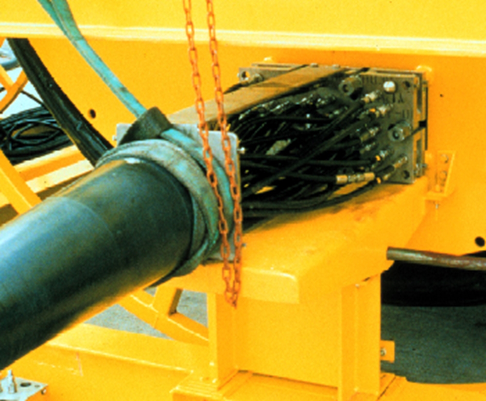
Control junction plates (also called MQC plates) for umbilical control hook up.
Control system. This includes the valve actuator command system and includes pressure and temperature transducers. The valve actuator command system can be simple tubing or a complex system including a computer and electrical solenoids depending on the application
Choke for regulating the production flow rate.
Flowloops for conducting production fluids, crossover between the production bore and the Annulus, chemical injection, hydraulic controls, etc.
Tree guide frame for supporting the tree piping and ancillary equipment and for providing guidance for installation and intervention.
External tree cap for protecting the upper Tree Connector and the tree itself. Tree cap often incorporates dropped object protection or fishing trawl protection.
Downhole Interface Unit, main function is to provide an electrical and communications interface between the downhole instrumentation and the Subsea Control Module.
Some components specific to production XTs like chemical dosing valves, multiphase flowmeters (single phase flowmeter used for water of gas injection XT), fluid sampling point, sand detector.

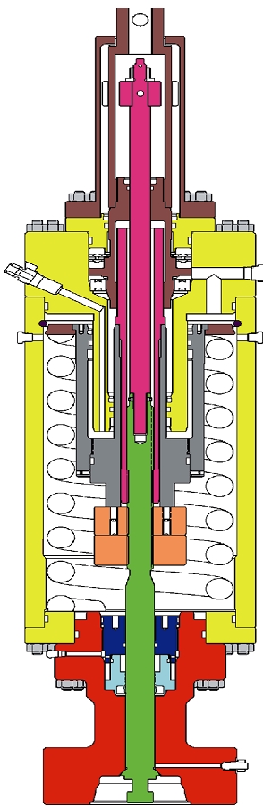
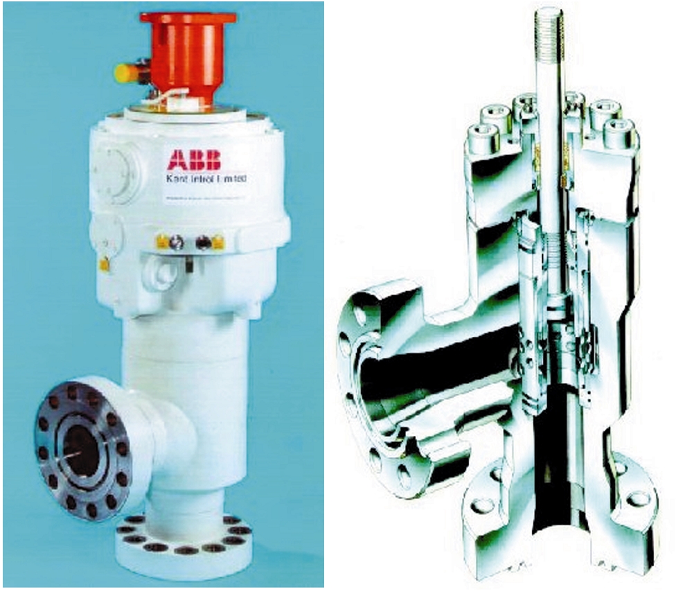
4.3.1 Chokes
Chokes are flow control devices designed to take the rigors of high pressure drop and high fluid velocities through the ports and across the seats. They are normally provided on the Christmas tree or less often, on the manifold, where more than one well produces to a manifold header.
Adjustable chokes provide flexibility for start-up and commingling of fluids from different wells and are commonly used. Chokes can also be used for controlled well shut-ins to prevent cutting across critical sealing valves at high flow rates. Chokes are not expected to be completely pressure tight and act as full flow shut off mechanisms though they often are capable of complete shut off until they wear. Due to the effects of erosion they often experience wear, and occasionally require replacement.
Some subsea chokes are designed to close rapidly for the purpose of saving the critical pressure retaining valves by closing before the valves do thereby eliminating potential cutting across the valve as it closes with high flow.
A fully adjustable choke actuator is a complicated part of the choke assembly with many moving parts and sometimes proves to be the part of the choke that wears out first requiring replacement before the choke trim.
Choke actuators normally include a means of ROV override to allow the choke to be adjusted manually if the actuator fails.
Choke actuators normally come in two design categories. They are either Stepping or Rotary drives. Stepping chokes are robust and provide very accurate trim adjustment but are slow and take significant times to open and usually to close. They may take 100 or 200 or more control pressure cycles to actuate the ratchet and pawl stroke mechanisms to fully open or close the choke. This can often take half an hour or more to fully open or close the choke. Rotary actuators are much quicker but less accurate and less robust than the stepping actuators. They are also smaller and cheaper. At high pressure, the flow rate is very sensitive and requires adjustment accuracy.
Hydraulic and ROV actuated chokes are both usually provided with a visual position indicator. In addition, hydraulically actuated chokes are normally provided with a position transducer.
There are a variety of choke trim designs and each has useful application for flow control depending on numerous factors such as fluid composition, flow rates, pressures, accuracy of control requirements, debris content, bi-directional flow requirements and others. The varieties of trim design for subsea applications include External Sleeve and Cage and Plug and Cage.
Choke trims are normally made from or coated with hard wearing material such as Tungsten carbide to prolong the life of the trim. Trims are sometimes designed so that the high velocity fluid impinges upon itself in the turbulent area of flow in the choke to also assist to prolong the life of te trim.
Reverse flow or even reverse pressure differential can damage some choke trim designs and thus if the possibility of this occurring exists, alternative designs should be selected. Instances where this can happen occur in fields where multiple wells are commingled into a single flowline or even during flowline commissioning pressure testing.
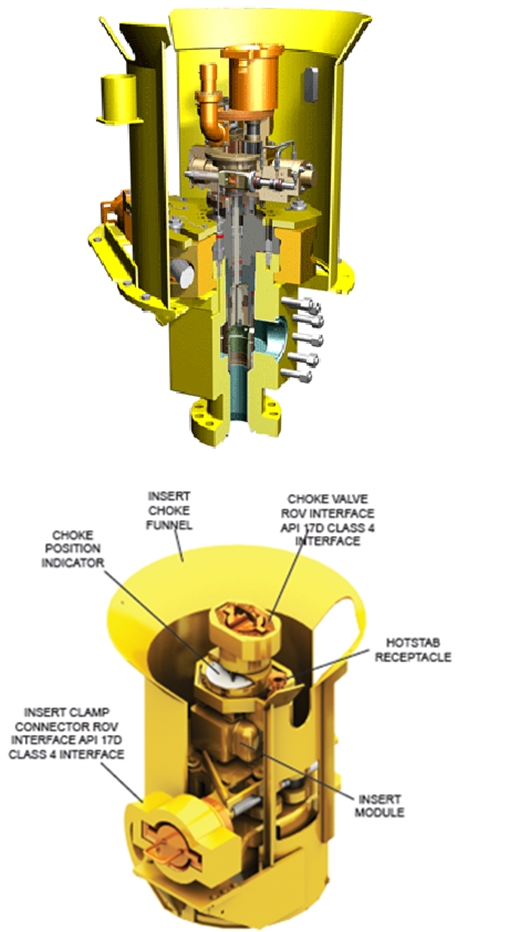
Subsea chokes are routinely designed and built to enable the remote replacement of the choke internals and actuator without retrieving the rest of the subsea hardware. The main outer body of the choke remains in place fixed to the piping on the subsea hardware. The choke internals or “choke insert” can be removed and replaced with a dedicated tool and ROV.
The retrievable choke insert is designed as a module that can be installed and removed using a running tool. These are sometimes run on guidelines, but in deep water are usually guidelineless and directed into guidance funnels by ROV.
4.4 Pressure and Structural Design Considerations of Subsea Trees
4.4.1 Pressure Design
Pressure containing components of subsea trees are to be designed and tested in accordance with API 17D (and also IOGP JIP 33 – S-561 – Supplementary Specification to API 17D Subsea Trees) and API 6A for pressure ratings of 5000, 10000 and 15000 psi (but also can exist for specific high pressure 20000 psi). The tree piping is normally designed in accordance with ASME B31.3. The guidelines in the API specifications are general and in many case open to interpretation. It is up to the manufacturer to apply his engineering judgement.
The sources of pressure in a Subsea Tree include the following:
Production fluids.
Hydraulic fluid. The hydraulic fluid pressure to the SCSSV may exceed the tree pressure rating. Effects of primary seal failures should be considered.
Chemical injection fluids. Seal failures can result in migration of fluids
Thermal expansion of fluids in closed cavities.
Annulus pressure. It should be assumed that pressure will accumulate in the well Annulus.
External hydrostatic pressure.
Test pressure. Seal verification.
Hydraulic lock. When mating parts are engaged, fluids may become trapped in the enclosed cavity and impede the engagement of the parts or cause damage to some component.
4.4.1.1 Seals
The rules of the ASME pressure vessel code apply for the design of pressure containing shells. Seal design, however, is largely beyond the scope of the pressure vessel code, and a great variety of proprietary manufacturer’s designs exist.
While the pressure design of the tree body, tree valves and piping is fairly straightforward, the interfaces between the various tree components require careful consideration or unexpected pressure effects may not be discovered until too late. It should be assumed that all seals are subject to failure, and at least one redundant or secondary seal shall be provided for every primary seal.
The following are some of the seal interfaces to consider:
Sealing between the production bore and the Annulus bore.
Tubing Hanger to tree interface.
Tubing Hanger to wellhead interface.
Tree Connector to tree body interface.
Valve blocks to tree body interface.
Valve seats, stems, gates, and bonnets.
Flowline and valve flanges.
Running tool interfaces.
Riser interfaces
4.4.1.2 Seal Materials:
Metal to metal seals. These employ a soft metal seal ring such as a stainless steel. The sealing seating surface is a harder material. Seal surfaces are usually overlaid with a non-corrosive material such as a high nickel alloy (Inconel). Metal seals come in a variety of forms including gaskets, rings, wedges and other geometric configurations.
Elastomer energized metal seals. These are composite metal and elastomer seals designed such that, the elastomer allows applied pressure to energize the metal seals, or confined elastomer compression squeeze energizes the metal seal during the setting procedure. Even with degradation of the elastomer, the metal component maintains the seal. Some designs include provision for potentially the opposite to occur in which the elastomer provides a backup seal for metal seals that may be damaged during setting or through use – for example fretting if movement occurs with temperature or pressure cycling.
Elastomer seals. The temperature rating and fluid compatibility of the elastomer is very important and shall be carefully considered.
4.4.2 Quality Control and Testing
Rigorous quality control and testing procedures are necessary to assure pressure integrity and correct fit and function of the components. Quality control, non-destructive examination and testing requirements are laid out in detail in API specifications. There are four levels of quality assurance defined in API 6A, called Product Specification Levels. Product Specification Levels dictate the degree of inspection, testing and certification required for the primary pressure containing components.
The following table summarizes PSL-2 to PSL-4. It should be kept in mind that API-6A was developed for surface wellhead equipment. PSL-1 is not usually considered applicable to subsea trees, and the applicability of the other Product Specification Levels is subject to interpretation. Subsea equipment will generally fall into the PSL-3 or PSL-3G (additional gas-testing requirement for assembled equipment) category and manufacturers often offer PSL-3 or PSL-3G for only nominally higher cost than PSL-2 because they have standardized on materials and procedures that comply with PSL-3.
Manufacturers of equipment almost always try to adhere to API specifications, but the customer should specify requirements when purchasing. All factory acceptance testing procedures will be generated by the manufacturer and should be reviewed by the customer to ensure that specific field requirements will be met by the equipment. System integration testing is another process that verifies that the equipment is suitable for use. These procedures are normally very project specific and relate to various equipment interfaces within the project. Refer to the section on testing.
Most manufacturers maintain a quality assurance system within their manufacturing and testing facilities to monitor and identify problems as early as possible in order that rectifying actions can take place as early as possible to prevent schedule delay. The method that most companies employ is for a report, often call a non-conformance report or NCR, to be generated. This report is created so that experienced engineers and/or customer representatives can review and decide on what course of action to take to assist the project meet schedule and quality goals. These quality systems are normally in compliance with ISO 9000 series specifications or API Q1 specification.
Manufacturing records of the material certificates, pressure tests and charts, non-conformance records, weld maps, non-destructive testing reports, x-rays, dimensional and weight logs and other critical information such as test reports are collected, maintained, and published by the quality assurance group in the manufacturing companies. These records or parts of these records are required by regulation in many parts of the world in order to be able to deploy and use the subsea equipment.
4.4.3 Structural Design
The Tree Connector, tree body, tree guide frame and tree piping must be designed to withstand internal and external structural loads imposed during installation and operation. The following are some tree and tree component load considerations:
Riser and BOP loads.
Jumper / Spool / Flowline connection loads.
Snagged tree frame, umbilicals or flowlines.
Thermal stresses – trapped fluids, component expansion, pipeline growth.
Lifting loads.
Dropped objects.
Pressure induced loads – external and internal.
Non-pressure containing structural components should be designed in accordance with AWS D1.1/D1.1M.
Tree framework is usually designed around standard API post centres. This is typically, but not always true, even if the tree is designed to be guidelineless. API defines the position of four guideposts evenly spaced around the well centreline at a six foot radius. This equates to 101.82 inches between the posts on any side of the square corners that they form.
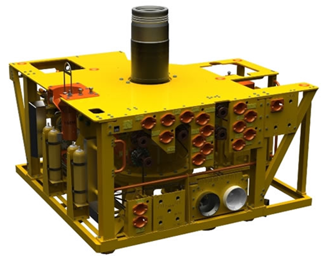
4.5 Tree Mounted Controls and Instrumentation
Tree mounted controls are dependent on operational, functional, and interface to the subsea system requirements. Typical tree mounted equipment includes the Subsea Control Module (SCM or pod) with mounting base and funnel, pressure and temperature sensors, choke position indicator, sand detectors, flowmeters, erosion detectors, downhole gauge interface, junction plates, and parking positions for both hydraulic and electrical jumpers.
The SCM is responsible for gathering all instrumentation data on the tree, including sensor readings from all tree mounted gauges as well as downhole gauge readings and sending that information to the topside control system for action and interpretation. The SCM also directs the hydraulic fluid supply via the appropriate solenoid valve to actuate a valve on the tree. The SCM can also record the “signature” of the valve by monitoring the outlet pressure on that line. The signature can be used as a diagnostic tool to by comparing to the normal signature of the actuator.
Junction plates are mounted on the tree to provide an interface point for the hydraulic, chemical and/or electrical jumpers or umbilical to mate to the tree to supply hydraulic signals, hydraulic power, chemicals for injection, electric power, or electronic control signals of the tree. The jumper Work-Over (WO) umbilical plates are also connected during installation and workover functions to allow the rig local control of the tree during these operations.
There are a variety of gauges that can be placed on the tree, separate (or combined) pressure and temperature sensors (intrusive sensors) can be placed in the Annulus and the production bore and upstream and downstream of the choke. The sand detector can be either intrusive or acoustic and be set to warn the operator in case of sudden or progressively increasing sand production.
Parking positions are included on the tree to allow parking of chemical/hydraulic jumpers, and electrical jumpers during workover, pulling of the tree or retrieval of the SCM.
The control system is described in detail in Section 6.
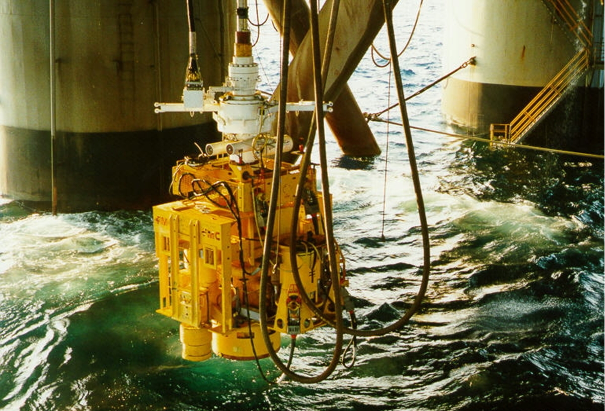
4.6 Subsea Tree Installation
4.6.1 Running Sequence on drill pipe/workover riser
The following is a summary of the typical sequence of operations for installing a Subsea Tree onto a predrilled well:
Move the rig onto location.
Launch ROV to locate the wellhead.
Establish final position over wellhead with the aid of the ROV and drill string reference positioning system.
If a guideline system is being deployed, re-establish guidelines.
Retrieve the corrosion cap from the wellhead. Check the condition of wellhead sealing surface with the ROV and flush if necessary.
Verify that a wellhead wear bushing is not in place. If it is, it will need to be retrieved. This is normally done through the BOP stack after it is run. For a Horizontal Tree, it may be retrieved in open water to avoid having to trip the BOP stack for just the wear bushing retrieval. This exposes the wellhead gasket sealing area to potential risk of damage. Extra precautions may be taken to avoid this such as an extended rubber tipped bull nose being run below the retrieval tool, or other means or guidance such as a guide frame.
Depending on the system design, a completion guide base or Tubing Hanger adapter spool may be deployed next. If not, the tree in a Horizontal Tree system will be deployed and then the BOP stack. Alternatively for a conventional system, the BOP stack will be run before the tree.
Horizontal Tree – An elevation check tool may be optionally run to confirm the height of the last Casing hanger in the wellhead with the same precautions mentioned above. The Horizontal Subsea Tree is then run on drill pipe with the Tree Running Tool and landed on the wellhead. The operation should be monitored by ROV. The umbilical should be strapped to the drill pipe as the tree is being run. The tree is then locked onto the wellhead and the gasket tested. The ROV then disconnects the work over umbilical junction plate and parks it above the Tree Running Tool. The Tree Running Tool and umbilical is then retrieved. The BOP and Marine Riser is then run and latched onto Subsea Tree. The BOP can then be tested by running the isolation test tool which is then retrieved. Completion work is then carried out and the tubing hanger run after the bore protector has been retrieved. The tubing hanger is run with the landing string and usually subsea test tree – refer to the section on work over risers. The well typically flows through the landing string for well clean up and well test purposes. A crown plug is set in the Tubing Hanger after the well test or clean-up is finished. An internal tree cap is then set and the BOP stack retrieved. A debris cap is then run onto the tree.
Conventional Dual Bore Tree – The BOP stack is run onto the wellhead before any completion work commences. An elevation check tool may be optionally run to confirm the height of the last Casing hanger in the wellhead through the BOP. Completion work is then carried out and the Tubing Hanger run after the bore protector has to be retrieved. The Tubing Hanger is run and oriented with the installation and work over riser configured for the Tubing Hanger running tool – refer to the section Section 4.7, “Installation and Workover Riser Systems” on work over risers. Plugs are then set in the Tubing Hanger and the installation riser and BOP stack are retrieved. The tree is then run on the installation and workover riser configured for the Tree Running Tool and lower Marine Riser package (LMRP). The plugs in the Tubing Hanger are then retrieved and the well tested or cleaned up through the installation and work over riser. The riser system is described in detail in section 4.7 below. The riser is then retrieved and a debris cap is run onto the tree.
The guidelines are then cut or released usually by ROV.
The rig then departs.
All of the above operations must be carefully planned before mobilizing offshore in order to avoid costly errors. In addition to all the logistical issues to be addressed, a part of the pre-planning should include consideration of weather limitations for the various operations and contingency plans for abandoning or suspending operations in case of bad weather.
4.6.2 Trees on Wire
Where drilling rig availability and cost are at a premium, operators have opted to run subsea trees on wire from a lower cost intervention vessel. The Tree Connector can then be locked to the wellhead and the connection tested via an umbilical from surface, or by ROV.
Light intervention systems have been developed to allow wireline operations to be performed subsea, such as running or retrieving plugs, using a subsea lubricator system. I.e. no riser required. With such a system, once the tree is run, the plug from the Tubing Hanger can be retrieved.
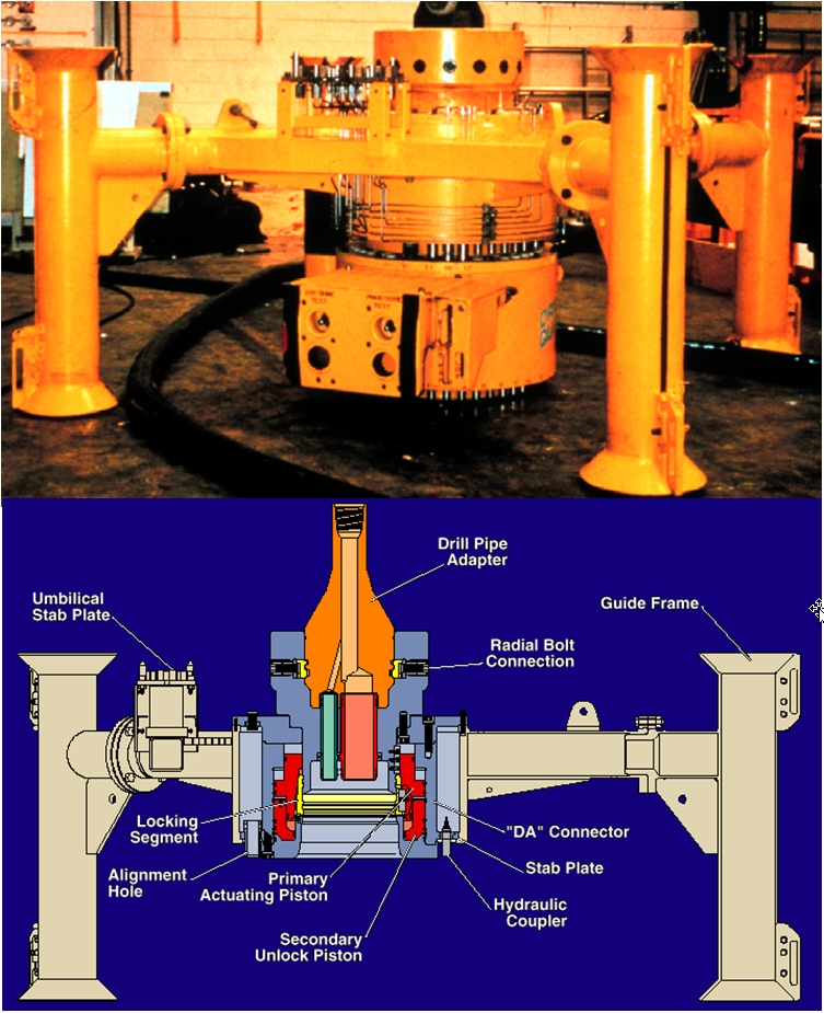
4.6.3 Tree System Running Tools
Subsea Tree and other equipment deployment require a suite of dedicated purpose designed running tools for the tree and tubing hanger. These are typically hydraulically actuated if they cannot be weight or tension activated. In deeper water, torque gets difficult to transmit and control to the subsea equipment because of the flexibility in the pipe being used to transmit it. In addition the pipe can have a tendency to curl if torque resistance is offered by the subsea tool. It is difficult to count the number of turns that the subsea tool receives because the observed number of turns at the surface may be different to the number of turns at the seabed. Visual indication of the function of the tool can thereby be confusing or lost leading to problems and often damage if test pressures or over pulls are applied with a tool incorrectly functioned.
Hydraulic tools can have hydraulic signals built into their design to confirm the correct function of the tool. Hydraulic signals can generally be assumed to reach the tool function if no pressure loss occurs which would otherwise indicate a leak. Hydraulic tools must be designed with a means of secondary override or fail safe to prevent problems in the event that the hydraulic system or umbilical fails while the tool is subsea. It would be undesirable to have a tool latched into a wellhead or tree with failed hydraulics so that it is stuck in place.
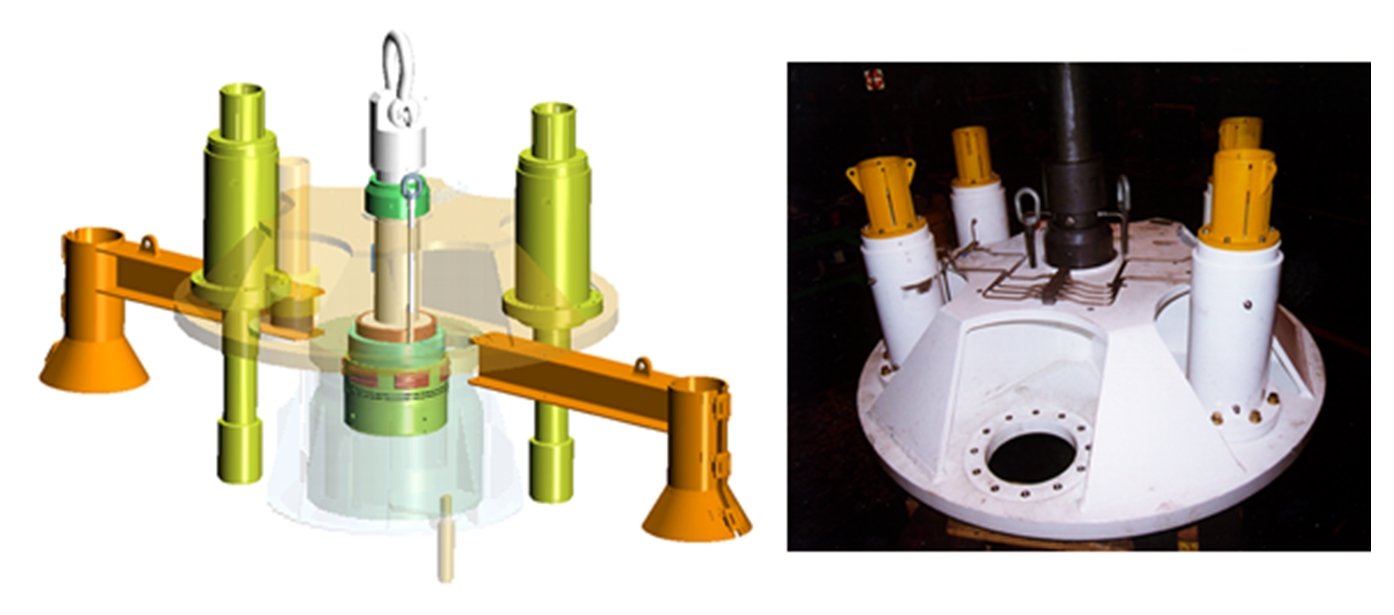
Figure 4‑20: Typical Tree Running Tool for Mechanical Connector (Hydraulics Are In the Tool)
4.6.4 Re-entry
Installation and workover systems are discussed in the section below. It also describes various options for umbilical connection.
The re-entry mandrel profile is a profile that is provided on the top of the tree. It is designed to provide a mechanical connection and pressure containment for the mating connector on the “Installation and Workover” riser system, or the subsea BOP in the case of a Horizontal Tree.
As an alternative to running a completion or Marine Riser, light intervention systems with a subsea lubricator may be used to perform certain through tubing interventions.
Recovery of the downhole tubing is another issue. With all vertical tree designs, the tree must be retrieved before pulling tubing. With horizontal trees, the tubing may be retrieved without pulling the tree.
4.7 Installation and Workover Riser Systems
4.7.1 Introduction
The primary functions of an installation and workover riser and associated equipment are to provide a means of lowering and setting subsea tubing hangers and/or trees and then to provide a pressure conduit into the well bore while simultaneously facilitating acceptable well control operations and disconnect possibilities during inert and live well flowing conditions.
There are different designs of installation and workover riser systems for different types of subsea trees and for different sized subsea trees.
4.7.2 Riser System Design Considerations
The design of a riser system requires investigation of a complex interaction of the following variables:
Pressure rating – the riser must be able to contain well shut in pressure
Bore size – wireline or coiled tubing equipment that will be used in the well must be able to pass through the riser, additionally the well fluid flow regime will be dictated by the bore
Structural strength – the riser shouldn’t fail when being handled, or with applied tensions and bending moments
Fatigue life – the riser must have a reasonable fatigue life – particularly if being utilized for a number of wells and for the life of a field.
Practical operating limitations for the riser – driven by factors including allowable operating envelopes to prevent over stressing the riser, handling and make up time on the drilling rig, and physical size and weight limitations.
Water Depth – affects loading on the riser
Sea States - affects loading on the riser
Current - affects loading on the riser
Vessel Characteristics - affects loading on the riser
Vessel Offset - affects loading on the riser
Rig Handling and Deployment
There are two basic operating scenarios for an Installation and Workover Riser. These are 1) Deployment within a Drilling Riser and 2) Deployment in open water.
Deployment within a drilling riser can be considered to be less severe service than deployment in open water in that the workover riser is shrouded within the drilling riser, but the variables noted above affect the performance characteristics of the riser in both scenarios as discussed below.
As the water depth increases, the bending loads on the riser reduce, but the tensile loads increase. In shallow water, the problems are associated with the limitations to the operating envelopes for the vessel. Very small offsets can produce high bending loads in shallow water. The vessel’s motion characteristics in response to the Sea State also have a greater significance on the loading and a greater influence on the fatigue life in shallow water.
In deeper water, the Sea States and vessel characteristics tend to have less influence and fatigue life improves. However, high currents can produce increased bending loading on a riser. This can lead to a lower fatigue life and a reduction in the operating envelope. When designing for deeper water, the wall thickness of the riser tubular may need to be increased in order to withstand the increased tensile loading, resulting in an increased stiffness. As the stiffness of the riser increases, the bending loads become greater and this again reduces the fatigue life.
Sea States provide the forcing functions that are applied to the vessel. The vessel characteristics determine the vessel’s response to these forces that result in the vessel motions. These motions are more significant to the riser in shallower water than deeper water and in combination with vessel offset influence the allowable operating envelope for both riser strength and fatigue life.
Sea currents have significant effects in deeper water. They cannot be neglected in shallow either. The currents can vary with depth, magnitude, and direction. The larger the diameter of the riser is, the greater the loading will be. In deep water, these loadings can create significant bending loads and fluctuating currents can result in greater fatigue loading despite depth.
To design a large bore workover riser for a multiple field role, a reasonably open operating envelope, a long fatigue life, shallow to deep water flexibility, under all conditions is probably impossible.
It is therefore preferable to define all these variables prior to initiating the riser system analysis. The resultant design would be specific to a fixed set of conditions, but could then be analysed for any variations in the conditions.
The specific limitations need to be developed and presented in usable form, usually as a set of operating envelopes of rig offset vs. sea state for each mode of operation of the riser.

4.7.3 Interface Considerations
A number of riser system interfaces that need to be considered whenever planning to deploy a rig and subsea system for installation or workover work on a subsea well include the following.
Vessel Response Amplitude Operator (RAO)
Met-ocean Design Criteria
Rotary Table
Vee Door Size
Rig Floor Facilities / Geometry
The BOP and component elevations
Effective Derrick Height
Coil Tubing Equipment
Drilling Riser System
Pipe Handling Facilities
Wire line Equipment
Riser Tensioning System
Maximum Hook Load
Riser Storage Capability
Subsea Production Tree
Control System Requirements
Subsea Intervention System
Tubing Hanger Running Tool
Coil Tubing Lubricator
Coil Tubing Lift Frame
4.7.4 Types of Installation and Workover Riser Systems
The primary Installation and Workover riser configurations are:
Conventional dual bore riser for operations carried out within a drilling riser while it is attached to an 18 ¾” wellhead and installing a dual bore Tubing Hanger.
Conventional dual bore riser for intervention operations carried out in open water while attached to a conventional dual bore tree.
Mono-bore riser for operations carried out within a drilling riser while it is attached to a Horizontal Tree and installing a mono-bore Tubing Hanger.
Mono-bore riser with a cross-over or selector mechanism for use with a conventional Dual Bore Tree system
Simple drill pipe or tubing configurations for basic functions are also deployed for running basic systems or simple elements such as debris caps and are not discussed here as an installation and workover riser configuration.
A brief discussion of these configurations is included in the following pages. Generally the descriptions of the riser systems and its major components start at the wellhead and move up the riser to the surface. Many of the principles for deployment and reasons for employment of different riser systems elements are shared between the different systems described. Obviously the design details may not remain constant between the various systems but will share common principles.
4.7.4.1 Dual Bore Conventional Riser System
Dual bore conventional risers are so named because they have two bores which enable wireline tool access into both the Annulus and production bores and because this is the traditional configuration for subsea trees until the advent of the horizontal tree design.
Subsea Christmas trees were originally designed so that the Production Tubing and Tubing Hanger would be installed in the wellhead through a subsea BOP stack and the tree later landed on top of the wellhead.
Access to the two bores is required in order to be able to plug the bores off with wireline set plugs to mechanically isolate the well. This isolation allows in turn enable the removal of the subsea BOP, allowing the installation of the Subsea Tree which mates with the Tubing Hanger.
Thus conventional dual bore tubing hangers and trees are generally run on dual string risers. The Tubing Hanger being run through the marine drilling riser and BOP stack before the tree is run.
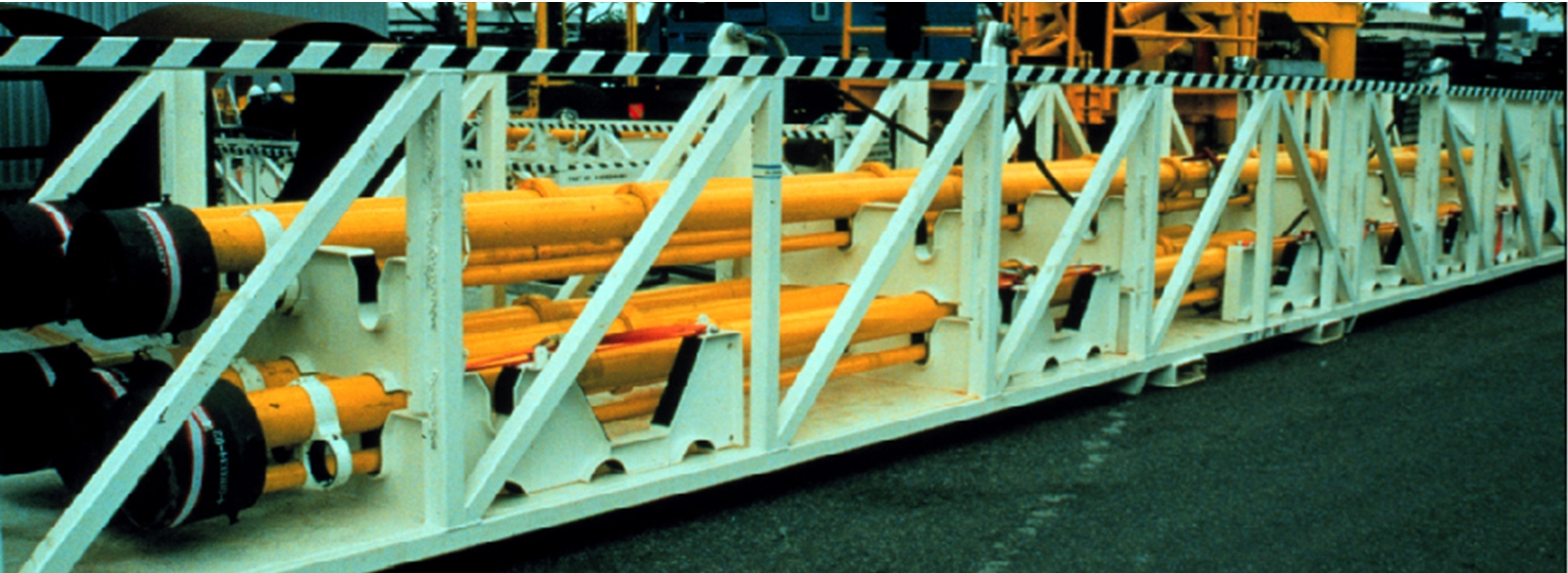
Dual bore risers are normally specially built for each conventional specific tree size and type. Refer to the accompanying figures for an outline of the different components of a dual bore riser string.
Figure 4.26 - Typical Dual Bore Conventional Riser System with Associated Tools, Adapters, And Accessories
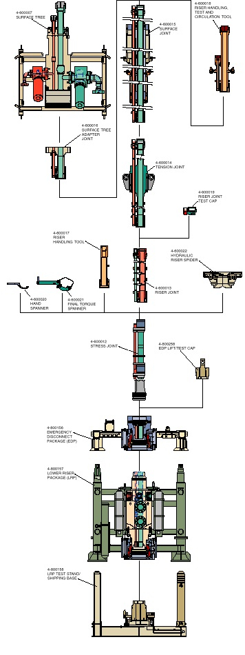
![[Note]](note.png) | Note The diagram shows only one riser joint (below the tension joint). The majority of the riser length in the field is made up of several of the standard riser joints. Various shorter length standard riser pup joints may be used to adjust to overall make up length – particularly if the riser is used for several different wells. The riser system is shown in tree mode. The tree (not shown) is picked up using the LRP. |
Figure 4.27 - Typical Dual Bore Conventional Riser System with Associated Tools, Adapters, And Accessories
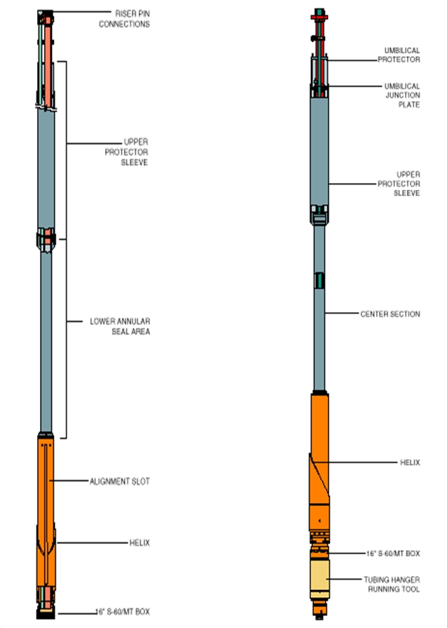
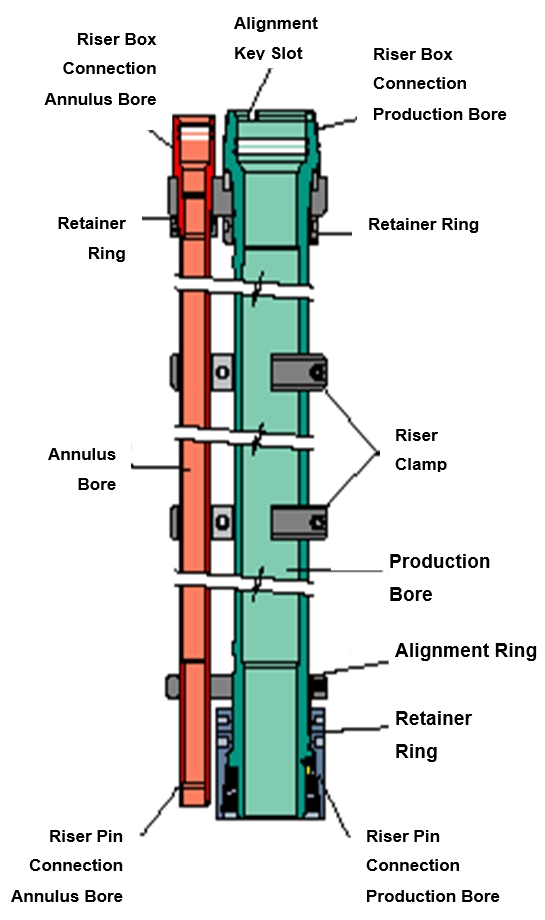
Figure 4.28 - Dual Bore Riser Configured With Orientation Helix (Rotated 90 Degrees In View On The Right). The Tubing Hanger Running Tool Is Shown With The Riser On Right – Omitted On The Left.
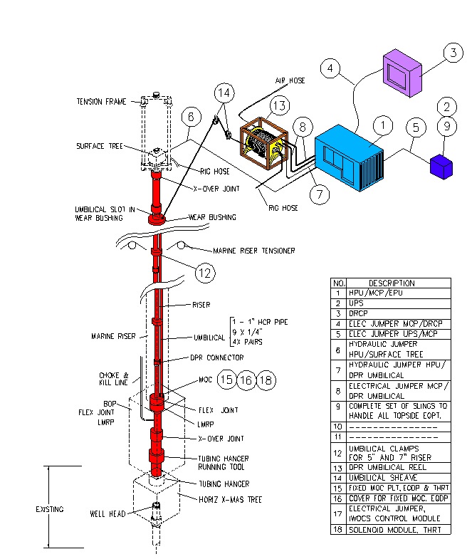
Figure 4.29 - A Dual Bore Riser System Configured To Run A Subsea Tubing Hanger Inside A Subsea BOP And Marine Riser
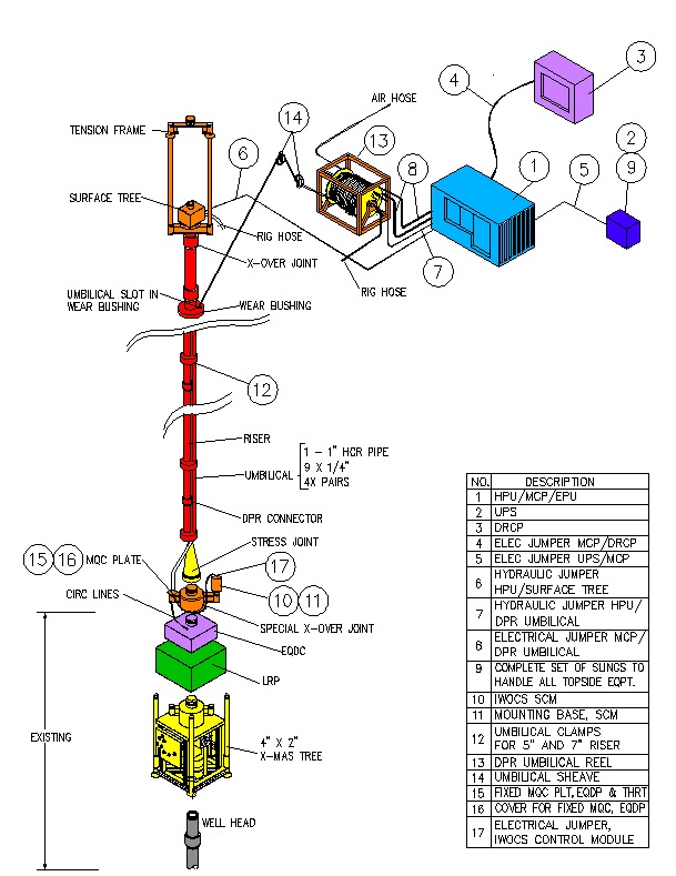
Figure 4‑28: Dual Bore Riser System (See Previous Diagram) After Retrieval of the Subsea BOP and Marine Riser, Ready to Run the Subsea Tree Onto the Preinstalled Tubing Hanger
Dual bore risers are typically specially built for individual tree designs and can represent significant investment. Consequently, operators may try to use a single riser design across a variety of projects, which can impose restrictions on tree design or selection options. This can also have the disadvantage of leading to equipment availability conflicts if more than one field requires work at the same time while a restricted number of riser systems are available.
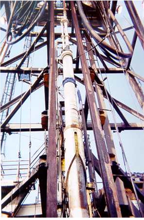
Figure 4.30 - Typical Dual Bore Riser Configured With An Orientation Joint Ready To Run A Tubing Hanger. Note The Helix Clearly Visible At The Lower End Of The Riser And The Dual Pipe Above The Slick Joint.
Dual bore risers have historically not been available on the market for rent. This may traditionally have been due to the fact that there are many different Dual Bore Tree designs with variables such as pressure, bore sizes, bore spacings and water depths different on different projects. Consequently large numbers of varieties of riser systems are required to accommodate all tree designs and equipment suppliers were not prepared to invest and have money tied up in varieties of riser systems.
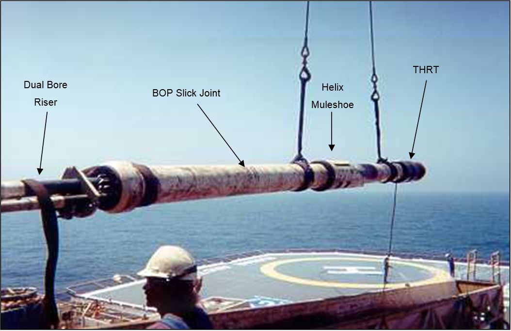
4.7.4.1.1 Riser System in Tubing Hanger Mode (THRT and THOJ)
The Tubing Hanger Orientation Adapter can also be referred to as the "Tubing Hanger Orientation/Extension Joint." An acronym for this item of equipment is "THOJ". As described above, the lower section of the THOJ includes an orienting sleeve configured with a helix leading longitudinal slot.
The Tubing Hanger orientation/extension joint includes two sections of flow pipe for the production bore and the Annulus bore. The lower end of the THOJ includes stab subs to connect the THOJ production and Annulus bores to the Tubing Hanger.
The middle section of the THOJ is smooth and has a reduced ID to allow both annular preventers of a typical subsea BOP stack to close for well control and for pressure testing of the tubing hanger seal. This area of the riser is often referred to as the “slick joint”. The lower end of the THOJ will normally include hydraulic stabs and sometimes electrical connectors that interface with the Tubing Hanger running tool.
Figure 4.31 - Dual Bore Tubing Hanger Orientation Joint With “Slick Joint” Clearly Visible – Shown Being Lifted From Its Shipping Basket To The Rig Floor
Umbilical clamps are located near the riser connections including at the top of the THOJ. The clamps secure the umbilical lines to the top of the THOJ. Hydraulic functions pass through the THOJ. This allows the BOP rams or annular bags to be closed on the joint and external pressure to be applied to the joint without affecting the hydraulic functions passing through it.

When the Tubing Hanger is tagged out during installation, a hydraulically actuated BOP orientation pin mounted through the BOP makes contact with the THOJ and engages the slot on the orienting sleeve. As the THOJ is raised, the BOP orientation pin contacts the edge of the orienting helix and forces the THOJ to rotate until the pin engages the longitudinal slot. While landing the Tubing Hanger, the pin remains engaged in the slot to ensure proper orientation of the Tubing Hanger. Note that the hydraulically actuated orientation pin is not normally standard on BOP stacks and has to be purposely installed for subsea installation and workover work. Note additionally, that various rigs have a huge variety of different BOP designs and stack up configurations. This means that the orientation system must be individually tailored to each rig. Consequently, the orientation system that may have been used to install a Subsea Tree system will more than likely have to be reconfigured to work the well over if a different rig is used for the workover.
After the Tubing Hanger has been run, orientated and set or locked down, wireline plugs are set in the two bores and the riser retrieved to surface. The BOP stack is then retrieved to surface.
4.7.4.1.2 Riser System in Tubing Hanger Mode (LRP and EDP)
The riser is then reconfigured to deploy the Subsea Tree. This reconfiguration starts at the bottom of the riser where a Lower Riser Package (LRP) and Emergency Disconnect Package (EDP) are installed. The logistics of how and when this is done will depend on particular rig operating designs and procedures but generally, the Subsea Tree is prepared in the moon pool and the LRP and EDP are stacked on top of it to be connected to the riser.
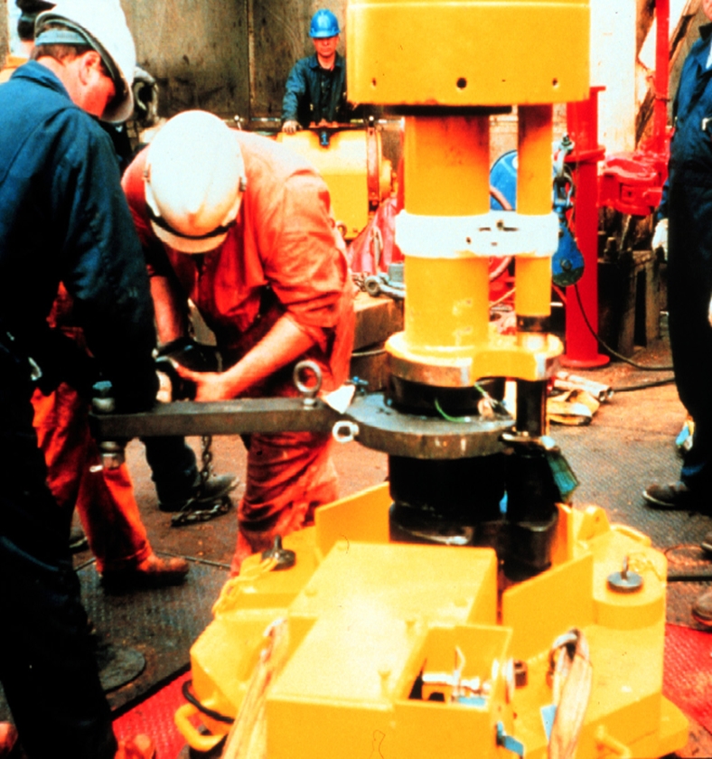
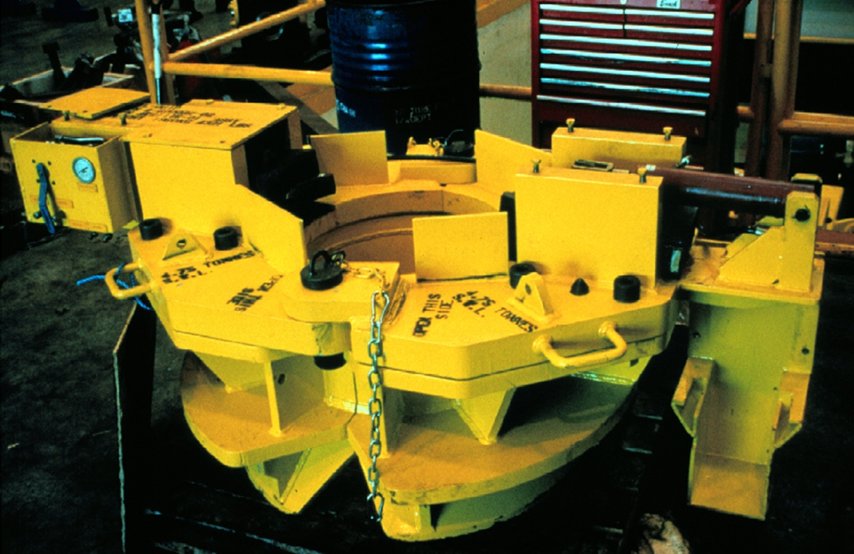
4.7.4.1.3 Riser Spider
When any type of pipe or riser is being run from a drill rig, some means of supporting the weight of the pipe must be provided. When drilling, rigs are equipped and set up to handle pipe at the rotary table through the use of “slips”. These are friction devices that are easily and quickly set and removed each time a connection is made at the pipe. Rotary tables and slips are designed for single round pipe.
Dual bore risers have two sets of pipe and therefore cannot be hung off at the rotary table with conventional slips. The method that is used to run dual bore riser is to employ a device often referred to as a spider.
The primary function of the Riser Spider is to provide a means to support the weight of the entire Riser or Landing String at the rotary table and thus relieve the hang-off weight from the travelling block. This allows the elevator to be unlatched in order to pick up another riser joint. The elevator is then available for handling joints as required, during the running and retrieving operations. For a dual bore riser, the spider enables slips to be set to hang off two strings. For all riser types, it also provides an opening for umbilicals, DHSV control tubing, and/or downhole gauge line(s) to exit from the rotary table master bushing to the rig floor.
The Spider’s last function can often be to provide guidance to the Surface Joint as it strokes through the rotary with the vessels’ heave, after the Tubing Hanger has been landed.

Figure 4.34 - Dual Bore Riser Being Made Up At The Drill Floor. Note Use Of Dedicated Spider For Supporting The Already Suspended Riser.
4.7.4.1.4 Lower Riser Package (LRP)
The Lower Riser Package (LRP) plays a major role in emergency shutdown (ESD) operations as dictated by the rig well test or other control logic system. Additionally, the LRP provides unrestricted access for wireline tools and coiled tubing when the LRP, tree, and Tubing Hanger are connected together. The LRP shuts the well in at the tree and is almost always designed to be capable of cutting wireline or coiled tubing in the event that they are in the well when the shut is required. The LRP, when shut in, will allow a safe disconnect of the riser and therefore the rig from the Subsea Tree and well even if the well is live.
Figure 4.37 - Typical Lower Marine Riser Package (LMRP) and Emergency Disconnect Package (EDP) On Its Test Stand.
All pressure containing components must have the same rating as the tree. A Lower Riser Package (LRP) usually includes three major components:
Valve block or Ram assembly with LRP connector and Re-entry mandrel
Frame
Control System
The LRP valve block assembly can be described as consisting of three portions: upper, center, and lower. The upper portion of the valve block assembly includes a re-entry hub. The re-entry hub includes production and Annulus bore seal pockets that mate with the EDP. The re-entry hub is the part of the riser system that enables disconnect and reconnect and is designed with seals that make up remotely.
A hydraulic stab plate is usually set at the re-entry hub, or is an integral part of the hub. It contains hydraulic couplers that provide communication to the LRP functions and to selected tree functions. It allows the installation workover control (IWOC) umbilical to be disconnected without damage if required with the EDP.
The center portion of the valve block assembly is usually a composite valve block and may contain small BOP rams or valves corresponding to the bore sizes in the tree and riser. The block houses production and Annulus valves or BOP rams or both.
The valves or BOP rams on the production and Annulus bores are normally fail safe-close design with a facility to shear. That is to say, if hydraulic power to the tree is lost, by for example umbilical damage, the valves or rams will close automatically, and will shear wire if in the well.
Often a crossover valve is an integral part of the valve block assembly and provides communication between the production and Annulus bores.
Methanol injection valves are often included in or on the valve block. Communication is achieved by direct porting into the production bore.
The lower portion of the valve block assembly is a hydraulic connector that locks to the subsea Tree Mandrel. The connector is designed for remote operation and often has facility for both primary and secondary hydraulic unlocking. The connector includes production and Annulus bore stab subs that seal in the tree upper seal pockets, and will also have visual indicators that enables an ROV, or other conveyed camera, or diver to ascertain the status of all relevant, remotely operated functions for the connector.
Control system hydraulic communication to the tree may be via a jumper with stab plate or via a lower LRP stab plate which fits onto, or is an integral part of the connector. Certain couplers connect to valves that can vent fluid pressure upon disconnect. All others are able to seal to prevent ingress of seawater upon disconnect.
Many tree systems are designed so that the when the installation and workover riser system is connected, it disables the host Production Platform control of the tree. This is often achieved by bridging hydraulic circuits through the tree cap. In workover mode, the tree cap is removed, breaking communication with the Production Platform. Communication to these ports is then from the rig via the LRP connector. A disadvantage of the tree cap which bridges the hydraulic lines is that this is invariably a complex and heavy design which must be run on rig time. If hydraulic functions are removed from the tree cap, then it is possible to design a ROV installable tree cap, which can then be done in parallel with other rig operations.
The LRP frame is a protective structure with bumper bars for protection of exposed equipment and guidance. Landing alignment posts on the LRP frame, or a guide funnel on the LRP connector provide, primary guidance for orientation of the EDP/LRP to the tree.
The LRP runs at the bottom end of the workover/completion riser string with the emergency disconnect package (EDP) latched to its upper mandrel profile. The assembled unit is then run on the dual bore riser system. The LRP lands and locks to the tree upper mandrel profile. The workover umbilical, which mates with a stab plate on the EDP/LRP assembly, provides communication from the workover control panel to selected tree functions.
4.7.4.1.5 Emergency Disconnect Package (EDP)
The Emergency Disconnect Package (EDP) provides the means for rapidly disconnecting from the Lower Riser Package (LRP) during completion or workover operations.
The top of the EDP consists of a connector which mates with the lower end of the stress joint at the bottom of the riser. The base of the EDP consists of a hydraulic connector, which engages with the re-entry (upper) mandrel on the LRP. The EDP is run latched to the re-entry mandrel of the LRP. EDP assemblies are designed to be capable of being unlocked with the riser being pulled over at angles of 3 or more degrees from vertical.
The connector will normally be designed to allow high angle release but sometimes, lift-off cylinders or jacks, which are activated after the EDP has been unlocked, are employed to lift the EDP connector up to make high angles of release possible.
Seal subs provide communication in both the production and Annulus bores. The bores have a pressure rating equal to the tree and provide unrestricted access for wireline tools and coiled tubing.
A hydraulic stab plate which mates with a corresponding plate mounted to the frame of the EDP is usually employed to terminate the installation and workover umbilical. Hydraulic communication to the EDP, LRP, and tree functions are typically routed through a stab plate mounted on the EDP frame. A hydraulic stab plate containing female hydraulic couplers is fitted to the body. This plate engages with a corresponding plate on the LRP to establish communication.
The EDP may contain a retainer valve, designed to close during the disconnection sequence preventing fluids in the riser spilling into the sea.
The EDP will normally also include a frame which acts as a protective structure and provides guidance for remote make up to the LRP Subsea Tree during running.
4.7.4.1.6 Stress Joint
A Tapered Stress Joint or stepped stress joint is included in almost all installation and workover riser designs. It engages with the emergency disconnect package (EDP) and provides a transition from the relatively flexible riser joints to the rigid EDP below, accommodating high bending loads.
It is called tapered because the wall thickness of the joint tapers from very thick at the bottom to thinner at the top – thus distributing stress more evenly through the joint than a straight pipe would. Alternative designs use a series of steps to provide the transition from thick wall at the base to thinner at the top. This is done because it is cheaper to manufacture and is almost but not as good as a true taper.
| Note The design of an installation and workover riser system and the stress joint in particular, is based on analyses that take into account the characteristics for a specific range of drilling rigs and the operating conditions under which it is anticipated to operate. |
4.7.4.1.7 Standard Riser Joints
Standard Riser Joints make up the largest length of the dual bore workover/completion riser system. They are used to run the EDP/LRP and Tubing Hanger running/orientation joint.
The riser joints have a dual bore design. One bore is the production line, which is normally the main load-carrying member. The second bore is the Annulus line. It provides communication to the Annulus bore but typically does not support any of the riser loads. It typically does not have connectors that restrain the pressure end load. Instead it is fixed to the production pipe with clamps that hold the pipe rigidly.
The riser joints are typically compatible with all other joints in the system. The joints are normally fitted with clamps, which can accommodate the Tubing Hanger running tool or installation and workover umbilical(s). The joints will be designed to land out securely in manual and hydraulic riser spiders for running purposes.
In addition to standard riser joints usually about 40- 45 feet long, there are typically 20 feet, 10 feet, and 5 fee. pup joints. These pup joints allow for optimization of space-out.
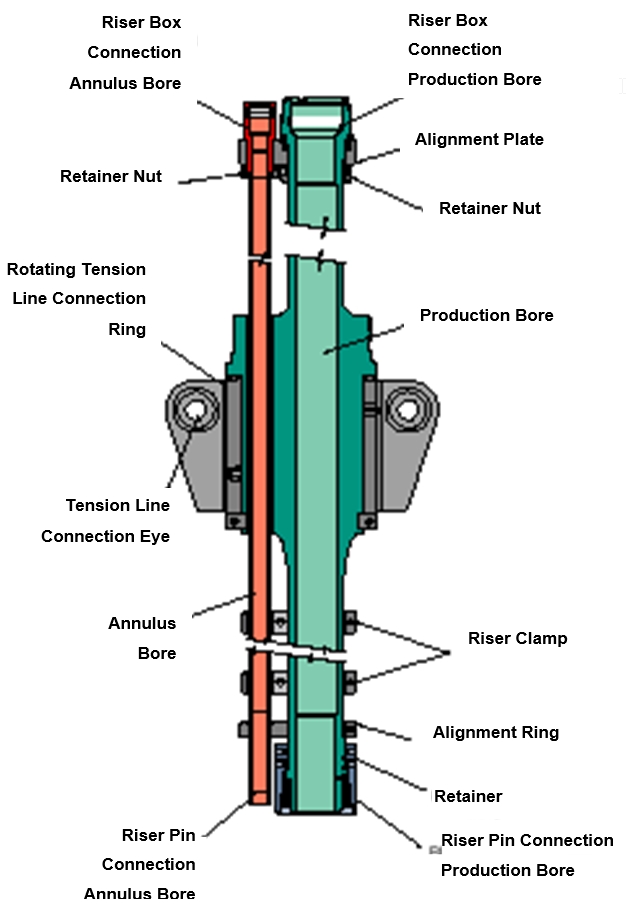
4.7.4.1.8 Tension Joint
A tension joint assembly is positioned near the top of the riser below the drill floor. It is used to attach motion compensated tensioning cables. The tension joint is a dedicated joint that provides a means of tensioning the dual bore riser system during completion and workover operations.
It is generally equipped with tension line connection eyes fitted to an independently rotating ring. The ring allows rotation without affecting the riser system.
The tension joint is compatible with all other joints in the riser system. It should be sized to be run though the 37-1/2" diameter hole in the rotary table after removal of the riser spider assembly.

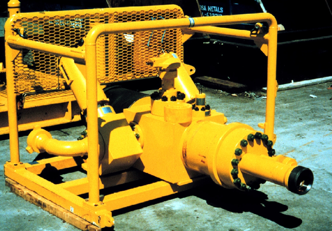
4.7.4.1.9 Surface Tree or Surface Flow Head
A Surface Tree is run at the top of the riser often just above an optional surface protection joint on the dual bore completion riser system. The surface tree is the primary control for the well during normal well testing or clean-up operations.
The optional surface protection joint protects the production line, Annulus line, and the Tubing Hanger running tool umbilical from damage at the point where the riser passes through the rotary table.
Valves fitted in both the production and Annulus bores provide a shear/shut-in mechanism during completion and workover operations. Both valves are normally capable of shearing braided cable or slickline.
The surface tree provides an upper flow control barrier for the riser. Its wing valves direct production flow to the choke manifold and well test equipment on the rig. Generally, a swab valve allows vertical access into the riser bore for wire line or coiled tube deployed tools.
Figure 4.43 - A Photo Of A Simple Surface Tree (Or Flowhead) For A Dual Bore Riser System –Shown On Its Side.
The riser weight is suspended from the surface tree that is in turn suspended from the crown block. A swivel is generally installed beneath the tree to enable the tree to be rotated to assist with the line-up of the choke and kill lines above the drill floor. For DP drill ships, this also allows the vessel to weathervane to suit the prevailing conditions. In a horizontal tree system, the swivel allows the Tubing Hanger to orientate when landing, or the tree to orientate in a Dual Bore Tree system. The swivel also eases the make-up of the last riser connection, if the connection is threaded or requires orientation.
The surface tree must also be elevated above the deck to accommodate vessel vertical movement. One of the limiting features of the surface tree is its overall stack-up height when combined with the Swivel, the Surface Joint and a Coiled Tubing Tension Frame inside the derrick.
Typically an elevator profile is machined below the upper connection on the surface tree to enable the tree and riser to be supported by the draw-works. A working platform is often mounted around the surface tree to enable personnel to operate manual valves and work the connection of the lubricator unit.
Lubricator adapters at the top of the tree block assembly enable the attachment of wireline or coiled tubing lubricators which in turn allow tool access to a live well bore. The production lubricator adapter is normally shouldered to be compatible with elevators for handling purposes.

| Note Only One Master Valve In The Annulus And Production Strings. Many Systems Contain Additional SWAB Valves Above Master Valves. |
Wing valves are fitted to outlets on the production and Annulus bores and are typically hydraulically actuated so that they will shut in automatically when tripped by the rig well test ESD.
A large (e.g. twenty-inch) Casing elevator profile on the block allows the tree to be suspended by a tension frame assembly – see description below.
The derrick system applies motion compensated tension to the installation riser. The load path could pass down bails hung from the travelling block, through an elevator to the surface flow tree and on down to the riser. However, this method restricts coiled tube and wire line access to the top of the tree. To obtain this access a tension frame is used above the surface tree. A coiled tubing gooseneck, injector head, and the lubricator can then be installed within the frame if required. It can take 24 hours rig time to change from the bails system to the tension frame and operators install the frame as a safety precaution.
| Note It is suspended from the travelling block in the derrick and it in turn suspends the surface tree (shown) and riser (not shown). It provides room above the surface tree for wireline lubricators (not shown) and enables the easy placement of a coiled tubing or snubbing unit if required. |
A surface tree is run at the top of the riser in the same manner and for the same reasons as in the dual bore riser system.
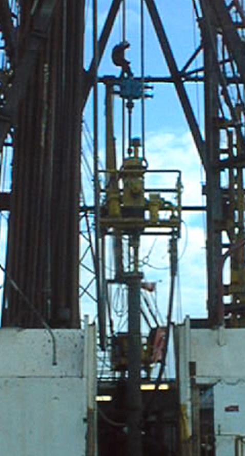
Figure 4.46 - Surface Tree In The Derrick – Note The Man On The Sling At The Wireline BOP To Install The Lubricator Above The Surface Tree.
4.7.4.2 Horizontal Tree Riser System
Horizontal trees are generally run on drill pipe with a tree running tool at the bottom of this “drill pipe riser”. The drill pipe riser and Tree Running Tool are then retrieved. Unlike the riser system for a conventional Dual Bore Tree described above, the Tubing Hanger is not run before the tree in a Horizontal Tree system and thus only one pressure containment riser is deployed.
The marine drilling riser which is part of the BOP system on the drilling rig is then used to deploy the BOP stack and become the environmental riser for access into the well through the tree, primarily for drilling and completion tubing deployment.
As the pressure rating of the marine drilling riser is typically very low – around 500 psi – and is almost certainly expected to be rated less than the well shut in pressure. The BOP rams or annular bags are utilized to isolate the Marine Riser from the well pressure if there is any form of kick during any of these preliminary Horizontal Tree operations by closing them.
Finally, when the Tubing Hanger is landed in the horizontal tree, it is done with the installation riser inside the marine-drilling riser. This riser is often referred to as the “landing string” because it is used to land the completion and Tubing Hanger. The riser is designed so that the BOP rams are closed on the riser during well operations once the riser is installed. This ensures that the Marine drilling riser is not exposed to high pressures.
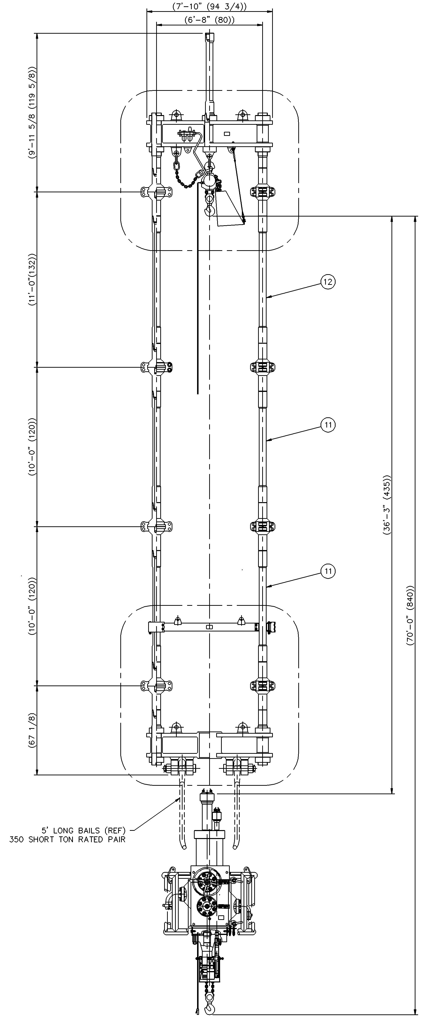
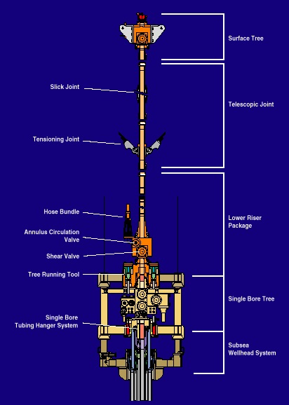
Figure 4.47 - Typical Horizontal Tree Installation and Workover Riser System Deployed Inside a Subsea BOP Stack.
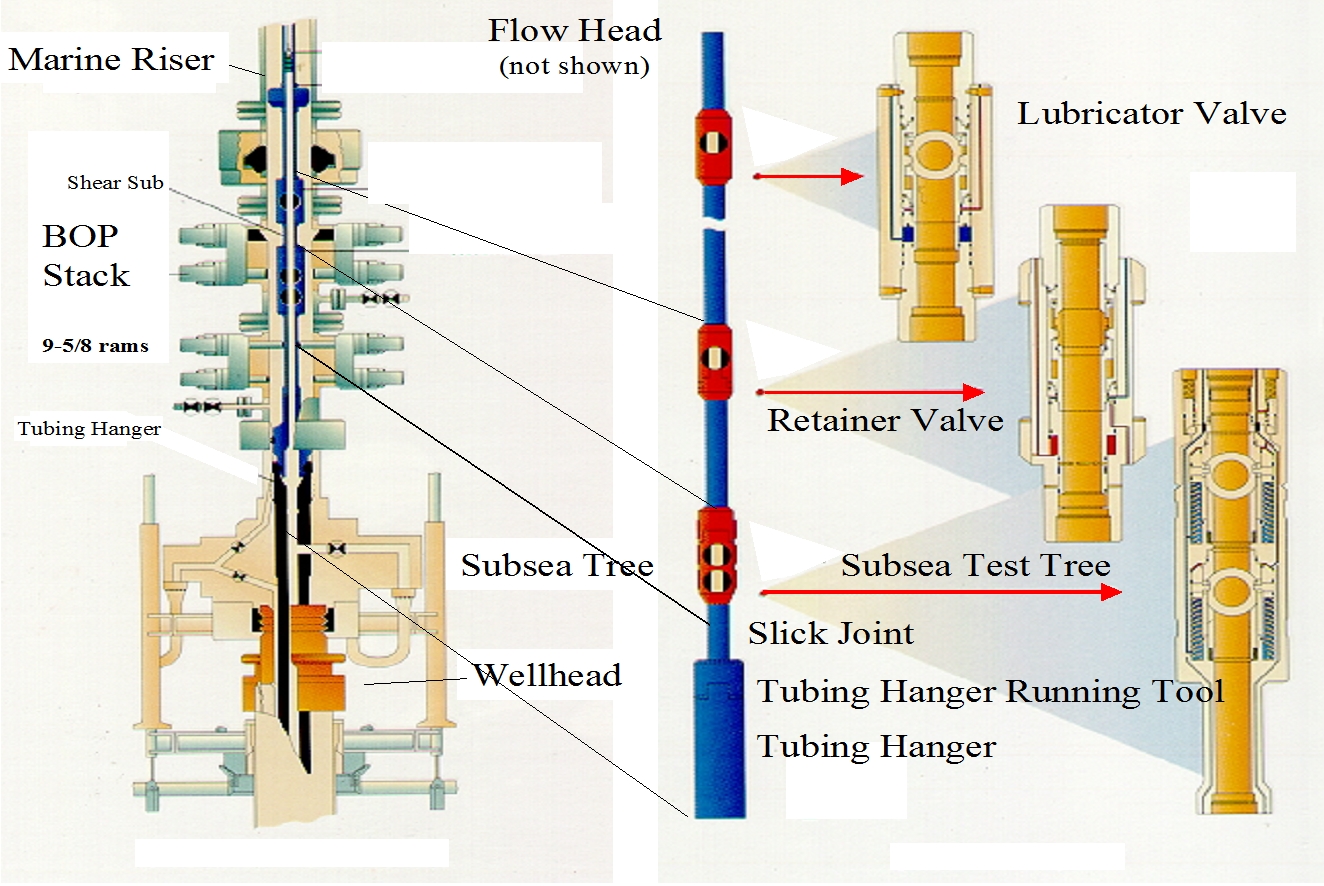
The installation and workover riser for a Horizontal Tree normally consists of premium threaded tubing or Casing and is additionally normally configured with a number of valves and disconnect mechanisms to safely handle a number of unplanned possible events that could occur that may compromise safety. This is the riser of interest and discussed below. All the valves and bore sizes must be suitable to pass the wireline plugs required in the tree. These are normally larger than any other tools or device than must pass into the Production Tubing down hole and usually dictate the size of the riser or landing string.
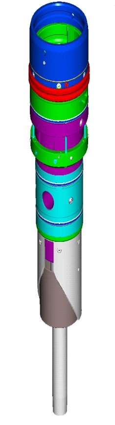
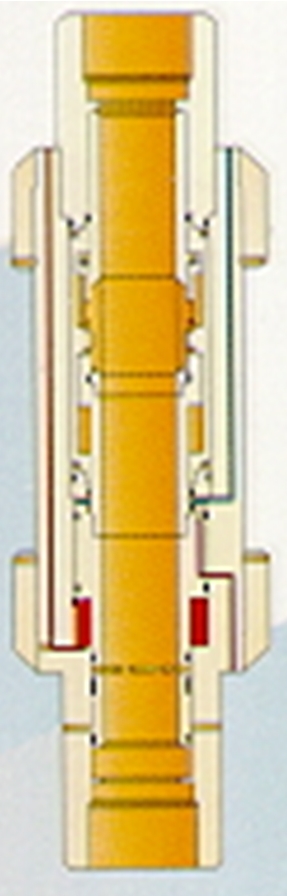
4.7.4.2.1 Test Tree
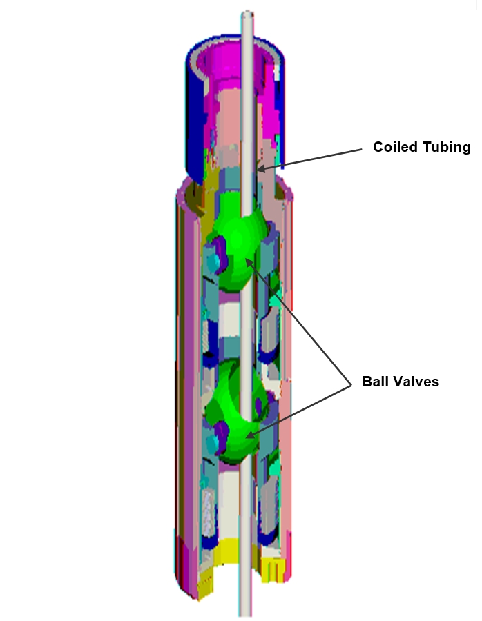
The subsea test tree (SSTT) is deployed at the bottom of the installation and workover riser for a Horizontal Tree system. The SSTT is typically configured with two valves. The tree is hydraulically operated and requires an umbilical to be run with the riser system inside the marine drilling riser. They are normally fail safe close valves.
The SSTT serves several functions.
The primary function of the SSTT is to provide valves at the bottom of the riser to shut-in the well at the tree if desired because there are no valves in the vertical bore of the tree. The valves are designed to be capable of cutting wireline or coiled tubing if they were in the bore at the time of closure and to be capable of sealing after cutting.
Another function of the tree is to allow the riser to be disconnected above the closed valves on the SSTT if desired. This feature is reversible and enables a remote reconnect if disconnection did take place. The SSTT connection system includes a hydraulic interface for all the hydraulic functions for the SSTT and the Tubing Hanger running tool. The reconnect feature is designed to be self-aligning and all stingers will only make up once the correct alignment is achieved.
The SSTT also incorporates a slick joint, which allows the BOP rams to be closed on the riser system. This serves to prevent high pressure from entering the marine drilling riser and as a secondary hold down of the lower end of the riser. The slick joint is generally at the bottom of the SSTT. If the Tubing Hanger running tool is hydraulically functioned (for deep water, they virtually all are), the slick joint will have porting through it for the Tubing Hanger functions. This allows hydraulic communication without hose or piping and thus prevents the rams or externally applied pressure from affecting the hydraulic functions. The slick joint is the interface between the SSTT and the Tubing Hanger running tool. Once the riser has been run, it can be tested against a closed valve in the SSTT for pressure integrity.
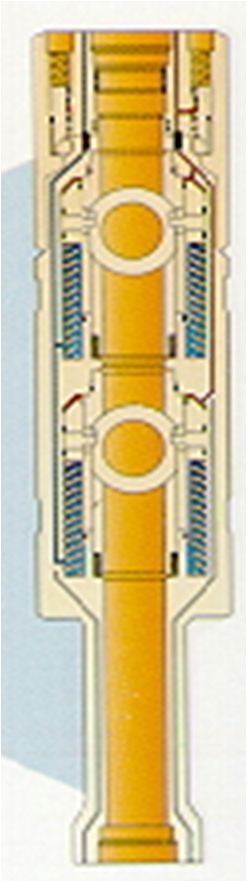
Figure 4.49 - Cut Away Section View of Subsea Test Tree (SSTT) Used With Horizontal Tree Riser Systems
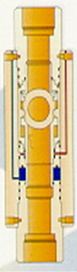
4.7.4.2.2 Retainer Valve
The retainer valve, or riser containment valve, is deployed low in the installation and workover riser, above the SSTT. The purpose for the riser containment valve is to prevent high pressure and/or hydrocarbons in the riser from being released into the marine drilling riser in the event of an emergency disconnect.
The release of hydrocarbons into the marine drilling riser or open sea is problematic, but the uncontrolled release of riser pressure into the marine drilling riser could prove to be catastrophic. This could launch the riser up into the rig floor. It could burst the drilling riser. It could divert large quantities of hydrocarbons including gas to the drill floor, which could burn or explode. It could evacuate the drilling riser then allowing external hydrostatic pressure to collapse it.
The retainer valve typically incorporates logic that does not allow a disconnect to occur until the valve is closed. The valve is hydraulically actuated. It is normally the termination point for the Tubing Hanger running tool and SSTT control umbilical(s). The hydraulic lines are typically ported through the body of the valve to the SSTT from the umbilical termination.
4.7.4.2.3 Lubricator Valve
The lubricator valve is an optional valve usually installed in the installation and workover riser just below the rotary table.
It allows long tool strings to be deployed in the well without exceptionally long lubricators being deployed above the surface tree above the drill floor.
4.7.4.3 Other Installation and Workover Riser Systems
Other tree types such as the “Thru-Bore” tree and mono-bore trees have utilized slightly different riser configurations from those described but they employ the same principles of well control issues and disconnect. The systems utilize hose access to the Annulus for circulation and pressure relief functions. The hose is typically of high collapse resistance design, and may be incorporated into the workover control system umbilical.
4.7.5 Well Test and Clean-Up of Wells
Among other things, installation and workover risers are used to flow wells for test purposes and/or for clean-up of wells before turning the well over to production operations.
This requires that the riser be connected to well test equipment on the rig, such as test separator. The well test equipment is used to handle the produced fluids. The well test equipment is not covered in the scope of this section.
4.8 Installation and Workover Control Systems
The Installation and Workover Control (IWOC) System provides control during installation, workover or other intervention operations. The IWOC system is an essential consideration in the design of the overall Subsea Tree controls and involves many interfaces.
As with the production controls, there are four main types of workover control systems. These are, direct, piloted, electrohydraulic (EH), and electrohydraulic multiplexed (EH-MUX) systems. The most common are the direct and multiplexed electrohydraulic systems with the others being considered to be older technology. Electrohydraulic systems typically employ subsea control modules in both Tubing Hanger and XT running mode. In Tubing Hanger mode, the module is mounted above the Tubing Hanger running string inside the Marine Riser. In XT mode, a module is mounted on the EDP or LRP and communicates with the XT subsea control module.
Selection of direct or electrohydraulic is a function of water depth, required response time, and number of functions to be controlled. Electrohydraulic systems can provide better feedback of volumes of fluid supplied or returned from subsea and downhole functions as volumes may be measured by flowmeters in the control modules close to the function. In direct hydraulic systems, all volumes are measured at the HPU, so include the uncertain volume of workover umbilical expansion / contraction.
In Tubing Hanger running mode, the IWOC system provides control of the Tubing Hanger running string. As well as operating Tubing Hanger running tool and subsea test tree (if applicable) functions, the IWOCS can provide control of downhole functions allowing their operation to be checked following running.
In XT running mode, the IWOC system must integrate with the production control system on the Subsea Tree and in many ways mimics the production control system to allow the rig control of the tree during installation or workover operations.
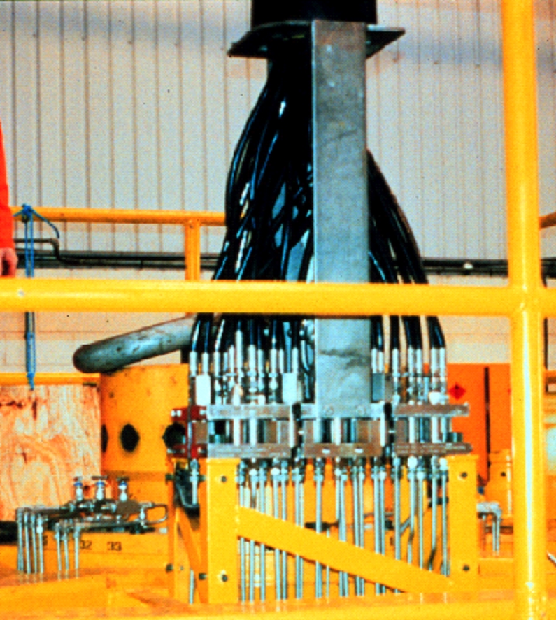
When first installing a tree, the rig must control the tree connector, valves for circulation, running tool hydraulics and other functions. The IWOC system also controls the LRP and EDP for a conventional or Mono-Bore Tree system.
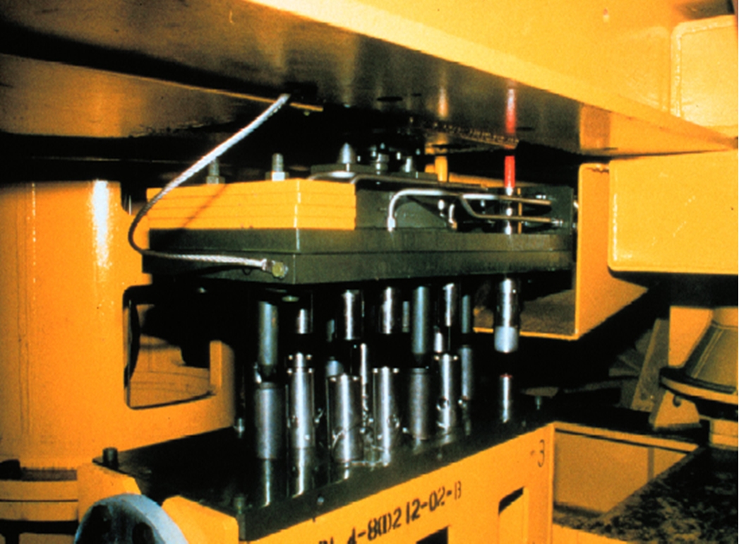
The hydraulic power unit (HPU) is the source for hydraulic pressure and power. The HPU will often include a control panel for directing hydraulic power as required. Larger systems may have a separate control panel. Direct hydraulic systems require a complex panel with panel mounted valves, gauges, hydraulic tubing and relays. An EH-MUX system relies on a computer as the control interface. The HPU typically includes a number of accumulators to store hydraulic power. These help to speed up response time when opening valves and prevent the pumps from stopping and starting continuously to compensate for pressure bleed-off.
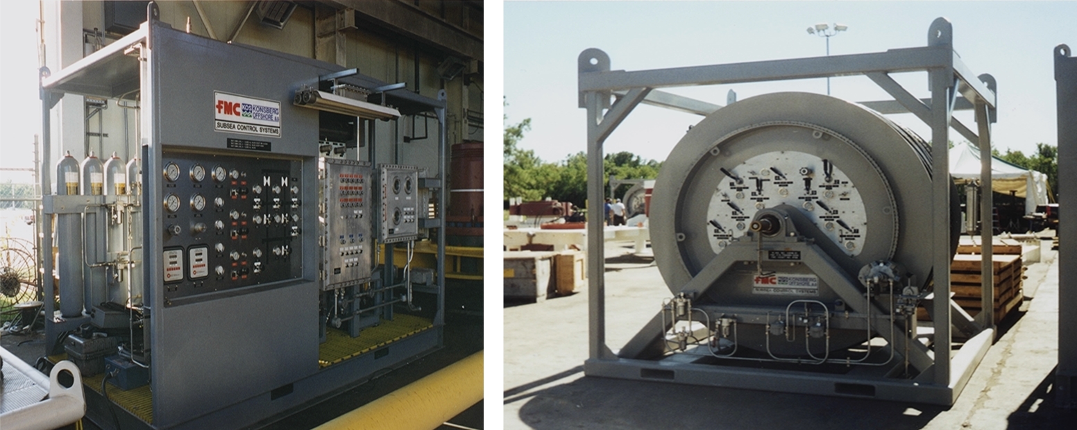
In addition to the main IWOC panel, some control functions may be included on the umbilical reels and often the side of an IWOC umbilical reel will be a mini panel. Hydraulic functions that are required to remain “live” (such as a Tree Running Tool or Tubing Hanger running tool) during the spooling out of the reel can be isolated at controlled on the reel. A single supply line can be connected through a swivel at the axis of the reel and distributed to the appropriate hoses in the umbilical through the reel mounted panel. After deployment of the umbilical the main supply jumper can be hooked up.
The IWOC system provides the controls and umbilical to operate the Tubing Hanger running tool, perform seal and gallery tests within the tree system, and the means for chemical injection for the tree and down hole as required.
Proper placement of the IWOC on the rig is important for running the umbilicals. The umbilicals are passed from reels through roller sheaves above the point where the umbilicals go down into the riser or splash zone. The umbilical reel needs to be located within line of sight of the sheave. The sheaves must be securely attached because the weight of the umbilical will be supported by them. It is good practice to have sheaves certified with a proof load and include weld NDE and load testing of the mounts.
The HPU can be located anywhere because the hydraulic power can be relayed or distributed to the various reels by hoses as required. The HPU is distributed to the umbilical and reel through jumper hoses that may run around the deck of the rig. The umbilical reels are typically air powered for paying out and hauling in the umbilicals. They should include a fail-safe brake that is released when air is supplied to the drive motor.