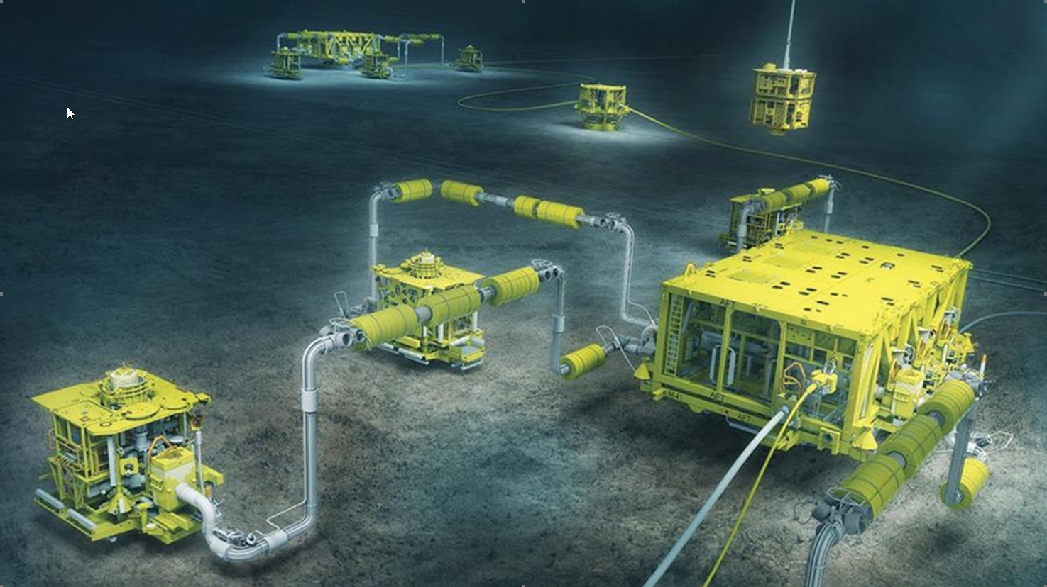
2 Field Architecture
2.1 Field Architecture Considerations
The purpose of the production facilities is to safely and efficiently recover the reservoir hydrocarbons, process them, deliver them to market and dispose of unwanted by-products. This involves many considerations and, as is the case with most field developments, must usually be undertaken with less than the desired amount of information. The objective is to maximize the return on investment within a tolerable level of risk. The numbers of issues to be considered are many. The following is a summary of some important ones:
Existing Infrastructure. Installation of new infrastructure in deep water is exceedingly expensive. The first thought when considering a new development should be to make use of existing infrastructure if possible. This includes existing production platforms, pipelines and even wells.
Well groupings. Clustering wells or installing well templates can facilitate drilling operations and save flowline cost. Drilling and well intervention considerations.
Optimizing intrafield flowline configuration. Well testing requirements. Pigging requirements.
Possible need for subsea production boosting (pumping) as part of the initial development or future needs ([137]).
2.2 Well Grouping
Field development planners need to work closely with the reservoir and drilling engineers early in the planning stages to establish a good well location plan. Once the reservoir is mapped and reservoir models created the number of wells, types of wells and their locations can be optimized. Well layout is usually an exercise of balancing the need to space the wells out for good recovery of the reservoir fluids against the cost savings of grouping the wells in clusters. Add to this the consideration of using extended reach wells, and the number of possible variables to consider becomes great.
A further consideration, reservoir conditions permitting, is the use of fewer, high production rate wells through horizontal well completions or other well technology. Here again, there are cost trade-off considerations.
![[Tip]](tip.png) | Tip Click these links below for access to 3D resources: |
2.2.1 Satellite Wells
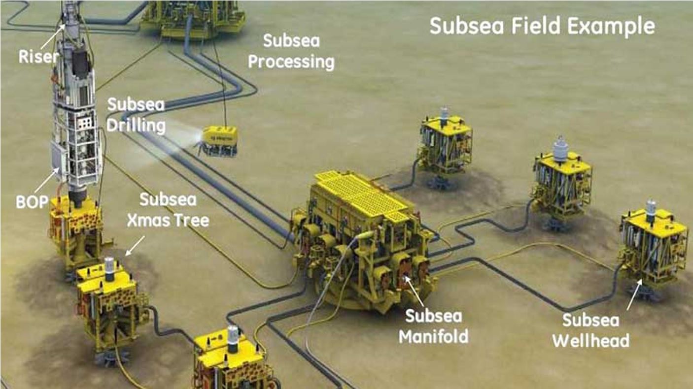
A satellite well is an individual subsea well, usually supported in a single free standing conductor. Satellite wells are typically used for small developments requiring few wells. Often the wells are widely separated and the production is delivered by a single flowline from each well to a centrally located subsea manifold or production platform. Various field layouts must be examined. This evaluation must involve hydraulic calculations and cost sensitivity analyses taking into consideration flowline cost, umbilical cost, installation cost, subsea production availability and flow assurance issues.
2.2.2 Template and Clustered Well Developments
If subsea wells can be grouped closely together, the development cost will usually be less than for an equivalent number of widely dispersed wells. Well groupings may consist of satellite wells grouped in a cluster, or a well template, in which the well spacing is closely controlled by the template structure.
2.2.2.1 Clustered Satellite Wells
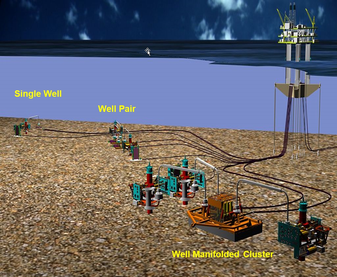
Clustered satellite subsea well developments are less expensive than widely spaced satellite wells mainly because of flowline and control umbilical savings. If several satellite wells are in close proximity to one another, a separate production manifold may be placed near the wells to collect the production from all the wells and deliver it in a single Production Flowline to the production facility. Also, a single umbilical can be used between the well cluster and the Production Platform. Figure 2.4, “Typical Well Cluster” shows a field with three clustered satellite wells, a Subsea Production Manifold and a single production umbilical and UTA.
In the case of clustered satellite wells, wells may be placed from several meters to tens of meters from one another. The wider well spacing is often dictated by a desire to be able to position the drilling rig over one well without imposing dropped object risk on adjacent wells, whereas a more compact well spacing can optimise well jumper construction and installation.
It is hard to precisely control the spacing of individual satellite wells, so well jumpers and control umbilicals must be able to accommodate the variations in spacing.
| Tip Click these links below for access to 3D resources: |
2.2.2.2 Template Manifold Systems
Another way of clustering wells is by means of a template manifold. Templates are structures that are designed to closely position a group of well conductors. Templates may support two wells or more than a dozen wells, as well as a manifold allowing direct tie-in of XTs.. Apart from reservoir considerations, the number of wells in a template is only limited by the size of the template that can be handled by the installation vessel. Small templates may be deployed from the drilling rig. Larger ones may require a special installation vessel with large crane capacity and without the moonpool dimensional constraints of a drilling rig. Heaviest ones (like template with overtrawlable structure) will require a heavy lift vessel. A discussion of the relative advantages and disadvantages of templates vs. cluster arrangements is given in Section 5.
| Tip Click these links below for access to 3D resources: |
2.3 Drilling and Well Intervention Considerations
Some of the drilling and well intervention issues that should be considered during subsea field development planning are:
DP rigs / drill ships are becoming more commonplace. However, where a moored rig is to be used, or where there is a possibility that moored rigs will be used during future workover operations, then the field layout should provide dedicate locations for rig anchors.
Again for moored rigs, the maximum excursion of the rig on its moorings should be considered, to position wells such that they can be drilled without relocating the rig anchors.
Safe handling zones should be defined, within the maximum excursion for moored rigs where applicable.
Wells should be spaced a minimum distance from other objects in elevation to avoid damage of other equipment due to BOP swing etc.
Installation schedule may be a consideration. Where drilling and installation vessel operations are planned to occur simultaneously, this may have implications for spacing of wells / manifolds.
2.4 Intrafield Flowlines
Intrafield flowlines are the network of pipelines between the individual wells, subsea manifolds, and production platforms. Intrafield flowline requirements will be established by the number of wells, well locations, well grouping and manifolding arrangements, well testing requirements, pigging requirements, gas lifting requirements, gas injection requirements, water injection requirements, operating pressures, production rates and shut-in pressures.
| Tip Click these links below for access to 3D resources: |
2.4.1 Flowline Routing
The most efficient arrangement of wells, flowlines, manifold and Production Platform is usually the one that results in the fewest number of flowlines of the least combined length. Other factors may force developers to consider other flowline routings, however. These include the following:
Differences in reservoirs and well performance. Some wells are capable of flowing greater distances than others due to their higher pressure or lower pressure drop (such as a high gas-oil ratio well versus a low gas-oil ratio well). This might affect where the production facilities are located or how the flowlines are routed.
Tie-back distance constraints, see section below.
The minimum laying radius for flowlines may constrain the possible flowline arrangements.
Direction of approach to the Production Platform. The flowlines must approach the hang-off on the side of the platform. Particularly in the case where the “platform” is a ship shaped FPU / FPSO, it may have a pre-determined orientation determined by the prevailing sea conditions. The type of riser system selected (tower, steel or flexible catenary risers, etc.) will also be an input to determining the flowline routing approaching the platform.
Avoiding hazards such as debris, outcroppings, canyons, or geotechnically unstable areas. Avoiding existing pipelines or cables.
Avoiding or minimising crossings of flowline / flowline and flowline / umbilical.
Differences in flowline metallurgy (such as a well high in CO2 versus one that is low in CO2). Minimizing the length of the more expensive (alloy) flowline might result in net savings.
Differences in pigging requirements. The platform might be best located nearer the wells requiring frequent pigging versus those that do not.
Providing clear areas or easements for future wells or flowlines.
Avoiding interference with Production Platform moorings. The same applies to drilling rig moorings if anchored rigs are considered.
The direction of approach to Production Platform, often dictated by the riser configuration.
The type of well fluid and thermal insulation requirements. A water injection line may be cheaper than a production line.
2.4.2 Tie-Back Distance
For a large scale new field development involving the installation of new production facilities, the Production Platform is usually optimally located relative to the planned production wells. Many marginal fields are developed using a subsea production system with subsea tie-back flowlines to existing production facilities some distance away. Subsea tie-backs are an ideal way to make use of existing infrastructure. Long tie-back distances impose limitations and technical considerations, however. The following are some of the main considerations:
Reservoir pressure must be sufficient to provide a high enough production rate over a long enough period to make the development commercially viable. Gas wells offer more opportunity for long tie-backs than oil wells. This issue can be overcome with subsea boosting technologies (subsea pumps or gas compression). Hydraulic studies must be conducted to find the optimum line size.
Because of the long distance travelled, it may be difficult to conserve the heat of the production fluids and they may be expected to approach ambient seabed temperatures. Flow assurance issues of hydrate formation, asphaltene formation, paraffin formation and high viscosity must be addressed. Insulating the flowline and SPS might not be enough. Other solutions can involve chemical treatment and active heating.
The gel strength of the cold production fluids might be too great to be overcome by the natural pressure of the well after a prolonged shutdown. It may be necessary to make provisions to circulate out the well fluids in the pipeline upon shutdown, or to push them back down the well with a high pressure pump on the Production Platform, using water or diesel fuel to displace the production fluids.
2.4.3 Commingling of Production
Commingling production is a good way to reduce the number of flowlines and save cost. Production from a group of individual wells may be commingled in a Subsea Production Manifold situated near the wells. The commingled production may be delivered in a single flowline to the production facilities.
When wells are commingled, the performance of the wells must be matched. Higher pressure wells must be individually choked so as to not impede the flow of weaker wells. If the expense can be justified, a HP and LP manifold can be provided with separate flowlines for each.
2.4.4 Well Testing and Multiphase Flow Metering
Good reservoir management requires individual wells to be periodically flow tested to measure their individual performance and production fluid characteristics. For dry tree production, a well testing manifold and test separator are usually provided as part of the topside production facilities. The flow from each well may be individually diverted through the test header to the test separator. The same can be done in the case of subsea wells.
For satellite wells with individual flowlines tied back to the Production Platform, it is often simply a matter of connecting the well flowlines to the well test manifold. A well test header may be needed ahead of the separator that otherwise might not be necessary in the case of dry tree production.
If the subsea production is coming from a subsea manifold, the subsea manifold could be provided with a well test header. This requires additional manifold valves for each tree, and a separate well test flowline to deliver the test well production to the test separator on the Production Platform. Sometimes, if only one flowline is available and several wells are producing into it, the wells may be “tested by difference”, that is one well which is individually shut-in and the difference in the production rate of each phase of the remaining production is measured. This requires a test separator large enough to handle production from more than one well, or metering on the production separator. Also, once the flow from one well is shut in, the flowline backpressure will change altering the flow from the remaining wells, making accurate assessment of individual well performance difficult.
This has led to the development of subsea multiphase flow meters. In most of the recent subsea production systems, a multiphase flow meter is provided for each well, mounted either on the XT (like on Laggan Tormore field), well jumper (like on Moho Bilondo field) or manifold (like on PAZFLOR field). As the name implies, a multiphase flow meter is capable of measuring the oil, water and gas phases separately, without the need for separation of the phases first. Further information on multiphase flow meters is provided in Section 6.
2.4.5 Pigging
Flowlines typically need to be pigged during commissioning to displace water following the hydrostatic testing of the system.
Pigging of flowlines is often necessary as a routine measure during production operations to remove paraffin deposits, produced sand and other debris that may accumulate in the flowline. Pigging may be done also as preventive maintenance, e.g. measurement of pipe wall thickness, as a remedy to an unforeseen fouling problem, or as a diagnostic tool.
In cases where hydrates can form at seabed ambient conditions, pigging of flowlines is often necessary to displace live production fluids and replace them with a stabilised oil to prevent hydrate formation during a prolonged shutdown (depending on heat performance and shutdown duration, recirculation is not required).
Different types of pigs are available for different situations. Some impose limitations on the pipeline design and should be considered beforehand. The following are a number of issues that should be considered when planning a field development that will include provisions for pigging flowlines:
2.4.5.1 Pigging Loops (Round Trip Pigging)
Because only one end of the pipeline is usually accessible from the Production Platform it is common to provide a looped path for the pig with the pig launcher and receiver on the same platform. The loop may be two pipelines parallel to one another with a pigging crossover valve at the far end from the Production Platform. The far end of the lines might be at a production manifold or an individual satellite Subsea Tree. Pigging operations require pushing the pig from the platform, through the crossover, and back again. A production well, pump, compressor, buy-back gas or other fluid pressure source must be available on the platform to displace the pig. Production operations might have to be curtailed, some wells shut-in or production re-routed during the pigging operations.
The extra line required for pigging may have uses other than pigging. During normal operations both lines could be used to handle production fluids, or one line might be used for flow testing one well while the other handles production from other wells, or one could serve as a high pressure (HP) production line while the other serves as a low pressure (LP) production line, or one is used to handle production while the other is filled with dead oil like in the case of an hybrid loop
(Hybrid loop available on Moho 1Bis Alpha Beta or on KAOMBO North and South production).
Satellite wells, each with a separate flowline to the Production Platform, may be connected to one another to create a pigging loop. A pigging tee would be required on each tree and a pigging crossover valve on one or both trees.
2.4.5.2 Subsea Pig Launchers and Receivers
Pigging loops become expensive for long tiebacks and pigging very long distances may be problematic due to the amounts of fluid involved, the time involved, or the pressure required to displace the accumulated wax and debris.
If operating conditions allow, consideration might be given to using a subsea pig launcher and pigging from the subsea production manifold or tree to the Production Platform. The production fluids can be used to propel the pig. It may be necessary to regulate the production rate so as to control the pig speed. The optimum speed is usually 1-2 m/sec.
Alternatively a subsea pig receiver may be installed at the far end of the pipeline and the pig driven from the platform to the receiver. Because of the problem of where to deliver the displaced fluid, this method is best reserved for pipeline de-watering, or other situations where displaced fluid disposal is not a problem. Sometimes a loop may be available but the pipeline sizes are incompatible. In such cases one-way pigging may be possible, by displacing the fluids from one section of the line into the other.
Because of the need for subsea intervention for subsea pig launching and receiving, this is best approached as a contingency provision for service that would require only very infrequent pigging. It is possible that a loaded pig launcher could be pre-installed on a subsea structure (FLET or manifold) prior to initial deployment so that subsea intervention would not be required the first time. Subsea pig launchers and receivers have not found wide usage. They are typically unique, project-specific designs.
2.5 Future Development, Expansion
Good field development planning requires making provisions for future development or expansion. Unfortunately, contingency provisions usually add cost, and it is often very difficult to foresee what the future development needs may be. The following are some future development planning ideas the subsea field development planners might consider:
Allow space for future satellite wells, including rig access. Make subsea trees compatible with piggy back flowbases (like used on GirRI Phase 1), such that future wells can be tied back to the manifold or platform via existing well jumpers or flowlines.
Provide spare subsea manifold valves and flowline tie-in provisions. Provide spare slots in templates for future wells.
Allow for tie-in of a “piggy back” manifold, e.g. via a removable pigging loop.
Allow space for future flowlines, or size flowlines to handle future capacity. Provide space for future risers on the production platform, or pre-install risers.
Design capacity for future wells into the production control system and production control umbilicals. Allow space for future umbilicals. Provide interfaces for additional flying leads on subsea manifolds or subsea trees.
Make provisions for future gas lift, such as pre-installing gas lift flowlines or configuring tree to accommodate a future gas lift tie-in.
Plan for future gas injection wells or water flood wells taking into account all the issues raised above for production well.
Design thermal insulation on existing facilities to be sufficient for future manifolds or wells tied back to the existing facilities from a greater distance.