6 Production Control System
In the present section is provided with an overview of subsea production control system. For a more detailed description refer to Deepwater Reference Book .
By its nature a subsea production system consists of a collection of discrete components. Since the components of a subsea production system are inaccessible for operator intervention and must work together in a coordinated manner, it is necessary that they be controlled remotely with an integrated control system. The control of the components of a production system is managed by the subsea production control system. The control functions include the following:
Opening and closing Subsea Tree production, Annulus, crossover and service valves.
Opening and closing the SCSSV.
Opening and closing Subsea Production Manifold flowline valves and pigging valves.
Opening and closing chemical injection valves.
Adjusting subsea choke position.
Monitoring pressure, temperature, sand production, flowrate, flow properties (for multiphase production fluid) and other data from tree-mounted, manifold-mounted or downhole instrumentation.
The following are some of the key design issues that must be considered when specifying or designing the subsea control system:
Offset distance. Distance affects signal strength, hydraulic pressure loss, response time and cost.
Valve control requirements: The number of valves, types of valves, quantity of control fluid volume required to open (or close) the valve (for hydraulically actuated valve), types of actuators, size of valves, failure position of valves.
Chemical injection requirements. Metering / throttle valve operation.
Instrumentation requirements: Pressure or temperature monitoring, pig detection, sand detection, flow metering.
Installation and workover requirements and interface with the IWOC system.
Redundancy requirements.
Expandability. Future wells, future flowline tie-ins.
6.1 Types of Control Systems
As Subsea Production Systems have increased in complexity, and water depths and step-outs have increased, subsea control systems have evolved from the basic Direct Hydraulic Control System, through Piloted Hydraulic Control Systems, Electro-Hydraulic Piloted Control System, and finally Electro-Hydraulic Multiplexed Control System.
Manufacturers are also developing all electric control systems since several years. All electric technology is a key technology for new subsea processing technologies, long-tie back, ultra-deepwater application and subsea factory. First application was in 2008 from TOTAL on K5F project (Dutch sector) with installation of full electric trees (supplied by OneSubsea).
In 2012, second generation of DC all electric system is developed by OneSubsea and in 2016 a first electric Surface Controlled Subsea Safety Valve (SCSSV) is installed on K5F3 development.
Electro-Hydraulic Multiplexed Control System today accounts for the majority of Subsea Control Systems used in deepwater developments, with the other systems being considered old technology. However, all the four main types of control systems are described in the following sections.
6.1.1 Direct Hydraulic Control System
The direct hydraulic control system is the simplest and least expensive production control system. It consists of a topside Hydraulic Power Unit (HPU) with one dedicated control line for each remotely actuated valve on the Subsea Tree. This type of system is typically recommended for 1-2 well tiebacks within 3 miles of the host platform. The advantages of this type of system are:
Simple and inexpensive.
Easy to maintain and diagnose problems.
The disadvantages of this type of control system are:
Umbilical tube required for each valve function (which is often impractical, and increased umbilical cost typically exceeds the cost savings associated with the control system itself).
Slow response time.
6.1.2 Piloted Hydraulic Control System
The piloted production control system is similar to the direct hydraulic control system, except that the valve that requires fast closing time will have a pilot valve and will vent to sea upon closing.
The advantages of this type of system are:
Improved response time for the critical valve.
Extends the offset distance possible for direct hydraulics.
Allows use of smaller umbilical tubes for the pilot operated functions.
The disadvantages of this type of control system are:
Higher cost than direct hydraulic system (mitigated by reduced umbilical cost).
Umbilical tube required for each valve function.
Response time still limited by offset distance.
6.1.3 Electro-Hydraulic Piloted Control System
This system consists of a topside electrical and hydraulic control system tied to one or more service umbilicals to the field. Each tree, well center or manifold has a subsea control module (SCM or pod) which takes LP and HP supplies and directs them to local valves when commanded by the topside system.
The advantages of this type of system are:
Improved response time for critical valves
Greater offset distance than hydraulic piloted system.
The disadvantages of this type of control system are:
Higher controls equipment cost than hydraulic piloted system.
6.1.4 Electro-Hydraulic Multiplexed Control System
The EH-MUX system consists of a topside electrical and hydraulic control system tied through a service umbilical to one or more trees, well centers or manifolds. Each end device or node in the system has a subsea control module (SCM or pod) which receive the multiplexed electrical control signals and the LP and HP hydraulic supplies and directs them to control tree or manifold mounted valves or other functions when commanded by the topside system.
The EH-MUX has become the industry standard for deepwater developments. This system accommodates future expansion easily, and facilitates control of numerous subsea valves, and data collection from numerous subsea instruments.
Both separate power and signal and combined power and signal systems are available, where the signals to and from the subsea control modules are super-imposed on the power circuit. The number of subsea control module electronics units which can be supplied on a single conductor pair differs from one supplier to another and depends on step-out distances. Where more than one conductor pair is required, the supply to redundant electronics modules within control modules can be carried on separate conductor pairs to maximise the system reliability and availability.
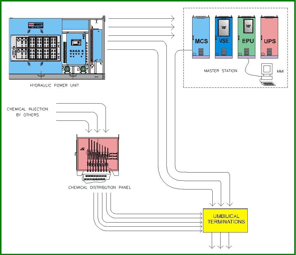
6.2 Production Control System Components and Functions
The figure below shows an overview Production Control System (Topside and Subsea Components).
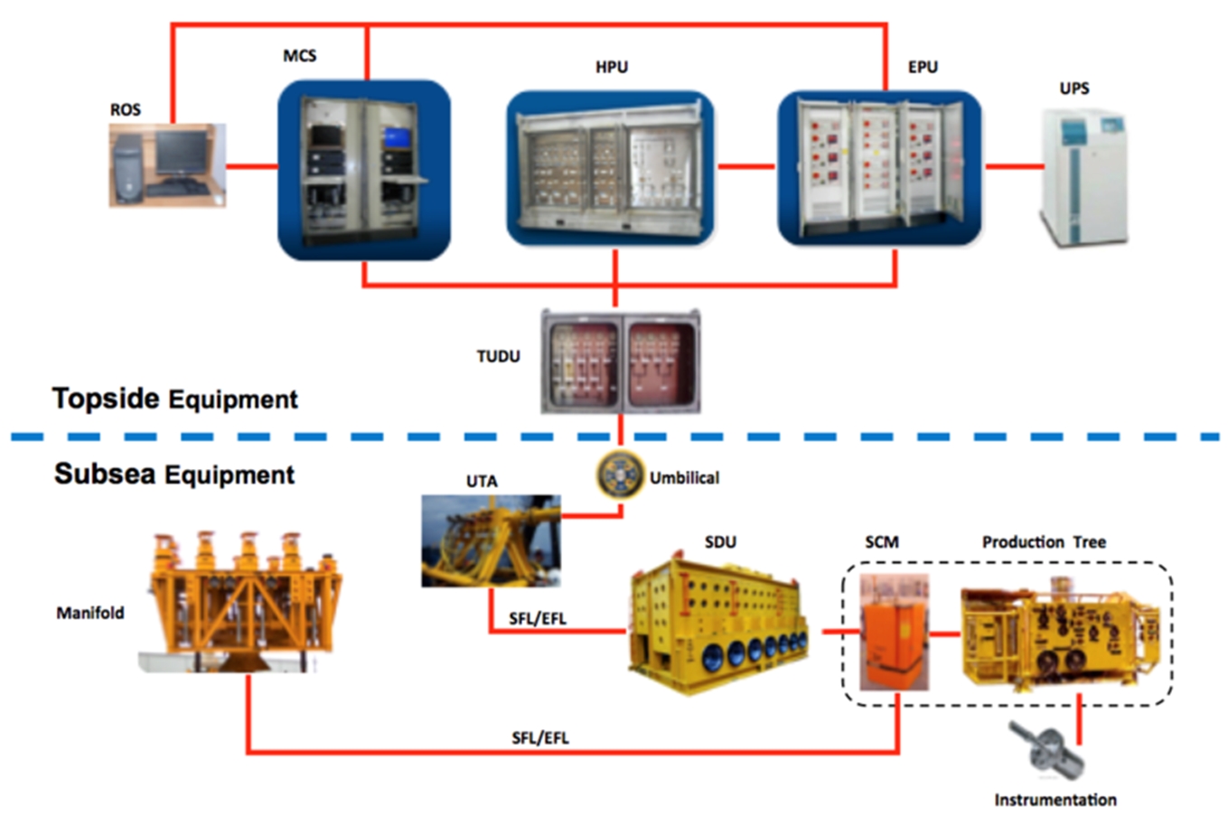
The following is a description of an electrohydraulic multiplexed production control system.
6.2.1 Topsides Control Unit (TCU)
Control of the subsea production system is managed by the Topsides Control Unit (TCU). The TCU is generally made up of three main components, the Master Control Station (MCS) the Electrical Power Unit (EPU) and the Hydraulic Power Unit (HPU). It should be noted that terminology and acronyms may vary from one supplier to the next.
The MCS and EPU are often integrated into the overall control and power supply systems for the platform.
6.2.1.1 Master Control Station (MCS)
The MCS is the “Master Control Station” which provides power, control logic and communications for the subsea control system. The MCS also provides the man-machine interface (MMI) for the control system. The MMI consists of a microprocessor based control system, display screen and keyboard for the operator to monitor the system and input and retrieve data. The MCS has the following main functions:
To condition the topside electrical power supply to provide two redundant, electrically isolated, protected, and regulated single phase power sources to the subsea control modules.
To provide the conditioning of the control signals into a format suitable for transmission though the conductors of the umbilical, compatible with the modem of the subsea control module.
To combine these two signals into a form that can be transmitted together on a single pair of conductors within the umbilical.
The MCS consists of a computer (or a serial interface with the platform DCS computer), power conditioners, modems and multiplex/de-multiplex (mux/de-mux) circuits.
The mux/de-mux circuits process the signal data so it can be transmitted over the same conductors that carry the electrical power. The output from the mux/de-mux to the subsea control system is typically a maximum of 690V.
Figure 6.4 - Master Control Station (MCS) for a Multiplexed Subsea Production Control System (GE VetcoGray)
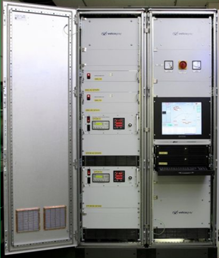
Figure 6‑4: Master Control Station (MCS) for a Multiplexed Subsea Production Control System (GE VetcoGray)
Two power channels within the MCS convert the power from the topside electrical Uninterruptible Power Supply (UPS). It is then at a level for transmission through the umbilical to the subsea control modules. Components in each output channel are identical and completely separate. Power modules, controllers and other components can be removed from one channel without affecting any other.
A line insulation monitor is incorporated on each power module to provide protection against insulation faults in the channel output line. The line insulation monitor has two alarm levels at adjustable resistance settings. At the first level an alarm signal is issued to the master control computer. At the second, lower impedance, the affected power supply is isolated and a secondary alarm generated.
The outputs from each channel are electronically protected against over voltage transients and over current. The voltage and current for each output are displayed on the controllers’ front panel and transmitted to the master computer for display.
Both the power channel outputs and the modem line connections interface with the umbilical via a power and signal combiner. A combiner is required for each channel. The communications circuits are bi-directional for both up-link and down-link transmissions. An output circuit breaker is fitted on each combiner.
6.2.1.2 Electrical Power Unit (EPU)
The EPU provides electrical power for the subsea control modules (SCMs). Power is generally supplied from a topside power supply with battery backup (UPS). The EPU monitors status of the dual redundant power circuits in the umbilical, and allows a circuit to be isolated in case of damage. Filters and modems in the EPU allow communication signals between the MCS and the SCM to be transmitted over the same circuits that are used to transmit power.
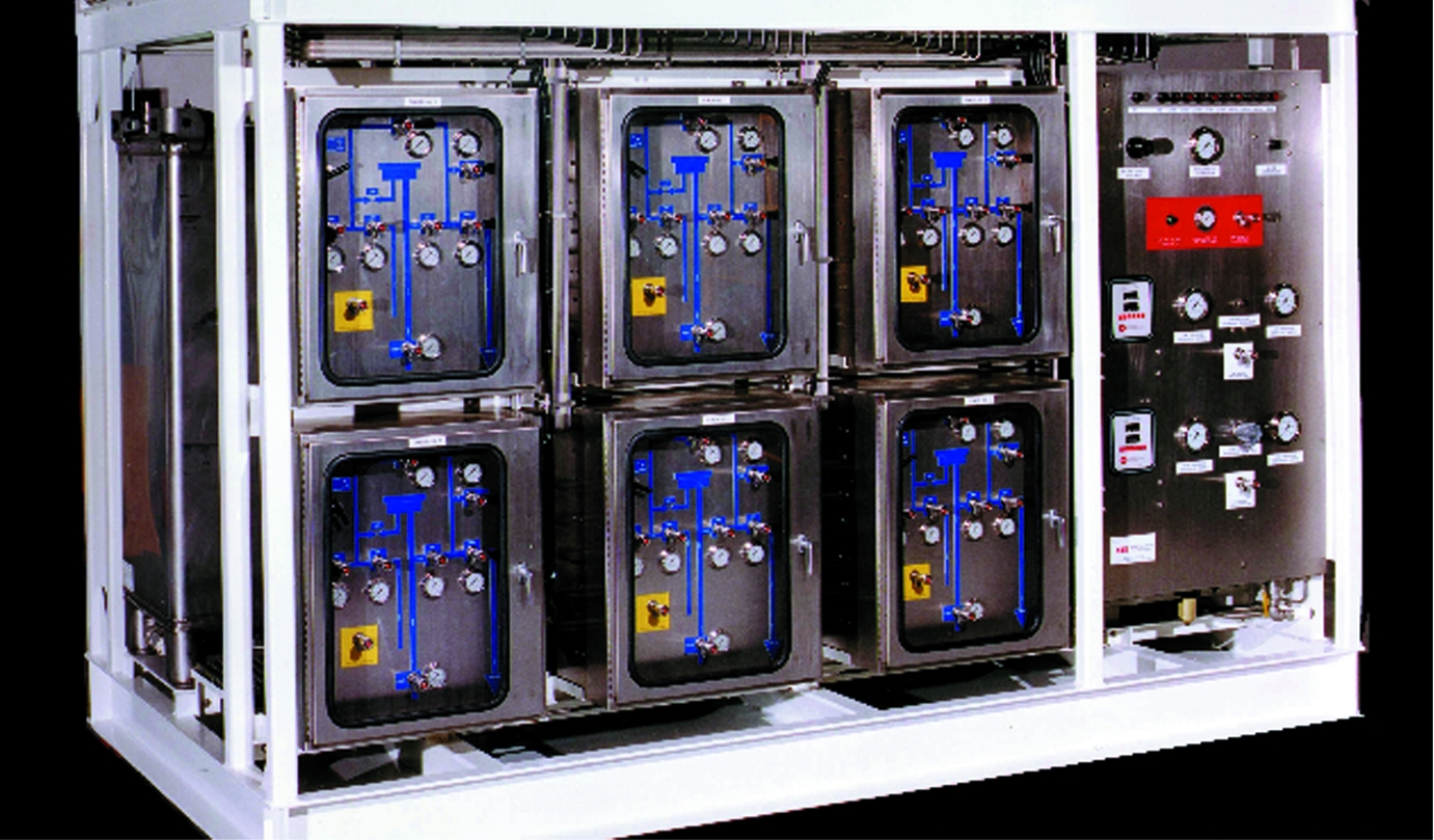
6.2.1.3 Hydraulic Power Unit (HPU)
The HPU supplies low pressure (LP) and high pressure (HP) hydraulic control fluid to the system. It includes two hydraulic fluid tanks (one supply and one return tank), hydraulic pumps, hydraulic accumulators, pressure regulators pressure gauges, flow meters and other instrumentation and controls. The HPU usually has redundant HP and LP pump and filter systems. The HPU is to be designed for use in the appropriate platform hazardous area classification. The hydraulic system uses water based control fluid. Typical control fluid cleanliness requirement is SAE AS 4058 class 6 B-F; although all components within the hydraulic system should operate satisfactorily up to class 10.
A hydraulic analysis should be performed when a field’s architecture becomes available. The key hydraulic considerations are:
Field layout (distances between wells and to the host).
Number of hydraulic users (valve actuators, chokes).
Umbilical characteristics (tube size, tube material, elasticity, fluid compatibility).
Actuator characteristics (volume, pressure opening speed required, closing speed required).
Number of open/close cycles in a given time period to design for.
Platform features (umbilical routing, elevation above water).
The hydraulic distribution system for the EH-MUX system is open loop with valve actuator returns vented to sea via a relief valve in the SCM.
6.2.1.4 Valve Signature Emulator (VSE)
The TCU sometimes will include a Valve Signature Emulator. The VSE records and monitors the pressure and flowrate over the time of the hydraulic actuation of the subsea valve (one valve actuated at the same time). Each valve will have its own unique signature. Using this signature data, the behaviour of valves during actuation may be monitored and malfunctions such as leaks, incomplete actuation or sticking actuators may be detected.
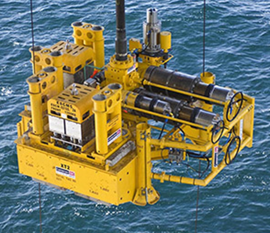
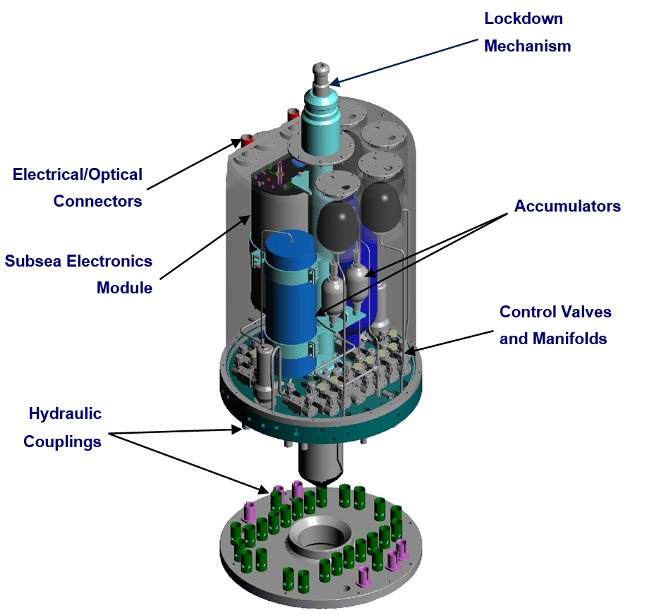
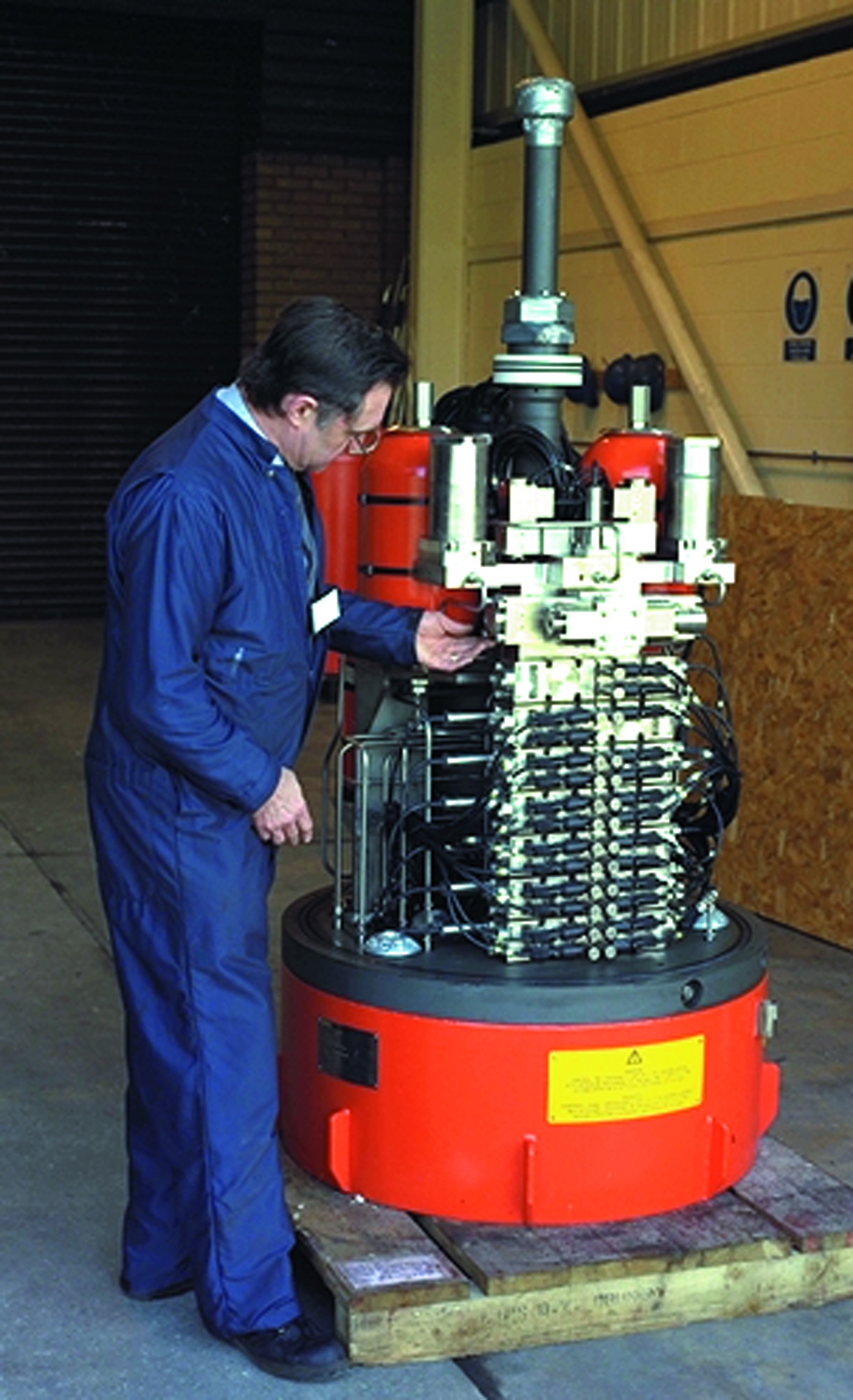
6.2.2 Subsea Control Module (SCM)
The SCM is the interface between the control system and the various end users, such as tree valve actuators, manifold valve actuators, transmitters, downhole valves, smart well functions, etc.
A SCM may be installed on a Subsea Tree, a manifold, a template or other component. One SCM can manage dozens of functions as well as digital and analog inputs. Individual SCMs may be linked together by control umbilicals and controlled as a single large integrated system.
The SCM is usually designed to be remotely replaceable using either a running tool or ROV. All electrical jumpers can be pre-installed, parked on the templates or trees, subsequently connected by ROV, and can be replaced by ROV if required. The SCM is normally installed with the tree or manifold, but may be recovered separately.
The SCM is a self-contained, pressure compensated “pod” consisting of a rectangular cylindrical housing containing directional control valves (DCVs), sensors and subsea electronics modules. The lower base plate (called the SCM mounting base - SCMMB) is usually integral with the tree frame or manifold structure. The base plate is the interface for all hydraulic functions and may also encompass interface for fixed mounted electrical flying leads. The SCM is usually filled with a dielectric fluid that acts as a secondary barrier against the ingress of seawater.
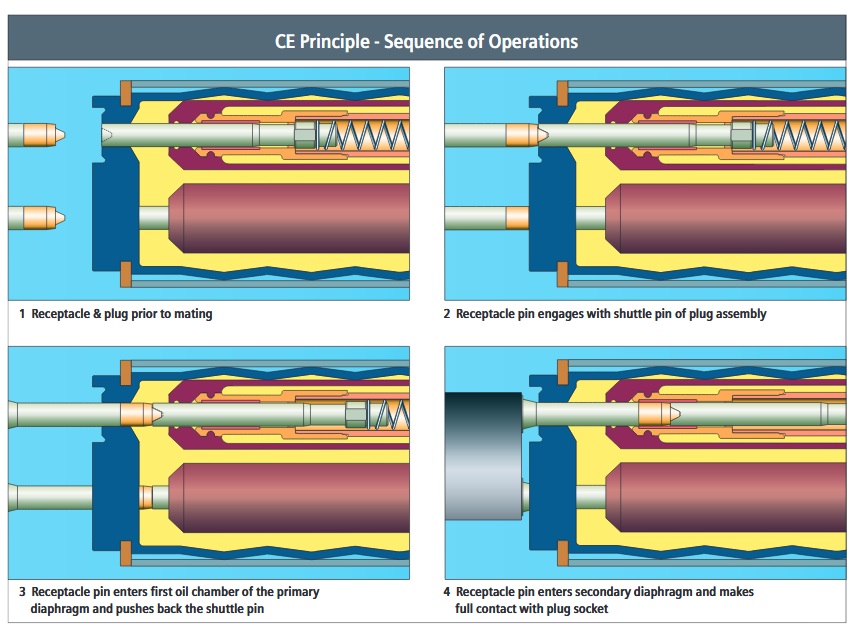
Power supplies, signal supplies and remote sensor connections are made up via ROV umbilical connectors. The connectors are high integrity controlled environment connectors with dual oil filled barriers protecting the contacts. Either SIEMENS (Tronic products) or TELEDYNE (Ocean Design Inc. ODI products) manufacture most of the subsea electrical connectors currently in use. Electrical connectors housings can be manufactured from duplex stainless steel grade UNS 32550, titanium or other suitable alloys. Typically the non-seal containing half (male pins) are mounted to the permanent subsea structures.
All recent TOTAL developments (PAZFLOR, CLOV, KAOMBO, EGINA) have been made with three different SCMs (Prod XT SCM, WI XT SCM and MCM), except for Moho Nord & Phase 1Bis where SCM have been standardized for both production & water injection XTs allowing interchangeability but it is still required to perform a specific set-up before subsea installation to configure it as a production or injection SCM.
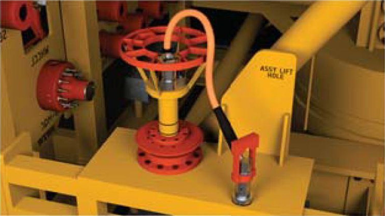
6.3 Subsea Instrumentation
6.3.1 Pressure and Temperature Sensors
Pressure and temperature sensors are typically mounted in pressure containing housings bolted to the tree or manifold block or pipework. As these sensors are not usually individually retrievable (tree needs to be retrieved to replace a faulty tree mounted sensor) dual redundant sensors are often specified. These may be in separate housings or dual sensor electronics in a single housing. The sensors usually are recessed in the housing, i.e. do not intrude into the flow path. Where thermal insulation is required for flow assurance reasons, design of the insulation around the sensors requires the balancing of a number of parameters, i.e. ensuring the sensor does not act as a cold spot, that the temperature sensor reads a representative value, and that the electronics components are not insulated so much that they overheat.
![[Note]](note.png) | Note Retrievable PT/TT sensor (intrusive PT/TT sensor from PRESENS) has been recently developed by TECHNIPFMC has been implemented on EGINA water injection XT. |
Figure 6.8 - Retrievable PT/TT sensor installed subsea (TECHNIPFMC Water Injection XT of EGINA Development)
6.3.2 Flow Meters
The main benefit of subsea flow metering lies in the ability to measure flow at the tree or manifold before commingling, thereby avoiding shut-in of adjacent wells for well testing or installing a separate well test flowline.
Single phase metering based on venturi technology has been applied extensively. However, their application is limited to single phase flow measurement, such as for water or gas injection wells, or for gas production wells.
Multiphase flowmeters have been developed many years ago, and have been applied in many subsea projects in recent years. The most common technology employs a gamma ray source passing through a stream of fluid, and inferring from the signal detected on the other side of the stream the relative fractions of oil, water and gas. The total mass flowrate is measured either by venturi, or by cross-correlation or a combination of both. The cross correlation method is based on detection of the same gamma ray signal using two sensors separated by a known distance apart, thus determining the velocity of the flow.
While they are relatively expensive instruments, their use can reduce project costs by avoiding additional well test lines and facilities as mentioned above. During production operations, they can provide superior information to traditional well test procedures, and in real time, allowing operators to better optimise reserves recovery.
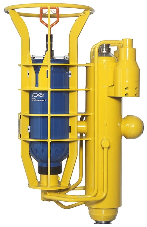
Generally, venturi single phase meters are non-retrievable. Multiphase meters exist in retrievable and non-retrievable forms. It can be mounted on PXT (as a single recoverable unit or inside larger module called Flow Control Module FCM) on well jumpers, manifold, etc.
Figure 6.9 - Subsea multiphase flowmeter with recoverable electronic canister (in blue) (Emerson ROXAR MPFM)
6.3.3 Sand Detectors
Sand erosion in subsea production equipment can be very destructive, resulting in catastrophic failures. Subsea monitors can warn of excessive sand production before too much damage is done. There are several types. One method commonly used in subsea applications relies on acoustic signals generated by the particles impinging on the walls of the piping. It is typically installed immediately past a bend in the piping. It can be strapped onto the pipe and hence can be non-intrusive and retrievable.
Other sand and erosion monitoring systems are based on measuring the change in electrical resistance of thin sensing elements which are eroded by sand. The system reads the erosive effect directly and is highly resistant to acoustic noise from pumps or variable flow. There is no need for calibration, and the system is particularly sensitive to cumulative erosion over time. Several sensor strips are used for redundancy and to cover the entire cross section of the pipe. The probe is read by sophisticated electronics. The 'raw' data are corrected using a reference element located on the back side of the probe. Software tools can predict worst case erosion on critical pipe elements such as chokes or bends based on erosion measurements or sand production data from other applications.
6.4 Umbilicals And Flying Leads
Umbilicals and flying leads provide the interface between the topsides control system and the individual subsea components.
![[Tip]](tip.png) | Tip Click these links below for access to 3D resources: |
6.4.1 Topsides Umbilical Termination Assembly (TUTA)
The TUTA gathers the hydraulic supplies hoses from the HPU and the electrical and signal cables from the MCS and provides a connection interface with the umbilical.
The TUTA has a junction box for termination of the umbilical electrical conductors and the platform cabling from the MCS. A set of valves can be added to this box for umbilical commissioning purposes. That allows filling and flushing of all umbilical lines from one point on the host.
Figure 6.10 - An Example Of A TUTA –Topside Umbilical Termination Assembly– The Subsea Umbilical Starts At This Box On The Production Facility. The HPU Ties Into This Point To Supply Hydraulic Power.
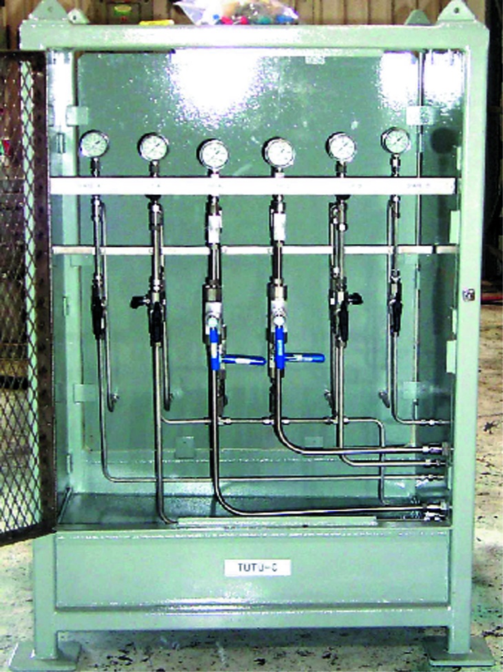
This unit goes by other names and acronyms, such as Topside Umbilical Termination Box (TUTB) (also called on many projects Topside Umbilical Termination Unit TUTU), Umbilical Junction Box (UJB), Production or Platform Umbilical Termination Assembly (PUTA), etc.
6.4.2 Umbilicals
The main functions of a subsea production umbilical are to deliver hydraulic or electrical control signals to subsea control devices and to convey injection chemicals to subsea trees or manifolds.
| Tip Click these links below for access to 3D resources: |
6.4.2.1 Umbilical Tube Materials
There are many options for umbilical tube materials. They include, but are not limited to, duplex stainless steels, thermoplastic hose, zinc coated carbon steel tube, and other alloys. Material selection is dependent on a number of factors, including pressure rating, chemical resistance, water depth and cost. For deepwater application, duplex or super duplex stainless steel tubes are most commonly selected. The following table is a simplified application guide for umbilical tube materials.
Material | Pressure Limitations | Services | Water Depth Considerations |
Thermoplastic Hose | 10,000 psi for 3/8” hose | Most chemicals. Methanol may permeate Nylon 11 liner. | Limited water depth. |
High Collapse Resistance (HCR) Hose | 10,000 psi for 3/8” hose | Most chemicals. Methanol may permeate. | Unlimited |
Super Duplex Stainless Steel | 15,000 psi for ½” tube | Most chemicals. | Unlimited |
Carbon Steel | 10,000 psi for up to 1-1/4” tube | Most chemicals. Hydraulic fluid cleanliness a possible issue. | Unlimited |
Note: This table is a guide only. It is recommended to check with suppliers.
Application guide for umbilical tube materials
6.4.2.2 Cross Section Design
Cross section design of umbilicals is dependent on the tubes size and quantity, tube material selection, desired hydrostatic resistance, desired dynamic characteristics and installation issues. For long offset distances weight can become an important factor. The umbilical must be handled by the manufacturer and transferred to the installation vessel. The installation vessel must have the tensioning capacity, and installation tensions can be very high, especially for steel tube umbilicals.

6.4.2.3 Umbilical Design Interface Issues
Table 6.1 - Umbilical design interface issues
Umbilical Supplier |
|
Host Facility |
|
Umbilical Installation Contractor |
|
6.4.2.4 Subsea Umbilical Termination
The ends of the umbilical are fitted with umbilical terminations. The end terminations are designed to take the installation and hang-off loads imposed on the umbilicals. A common method of transferring the imposed loads into the umbilical is through the use of an armour pot. The pot interlocks with the armouring or other structural components in the umbilical without loading the hoses. End accessories can then be mechanically fitted to the armour pot. The end termination often includes a bend restrictor to prevent excessive bending stresses at the connection during service or installation.
Individual cable terminations are commonly fitted with caps offering protection during deployment. The caps may also feature resistive loads between the individual pins to enable monitoring of the umbilical conductors for any faults during installation.
Hose connections are also fitted with protective caps. The hydraulic caps may also contain loops to facilitate umbilical commissioning.
| Tip Click these links below for access to 3D resources: |
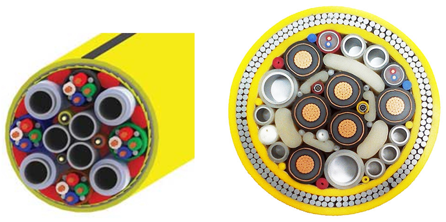
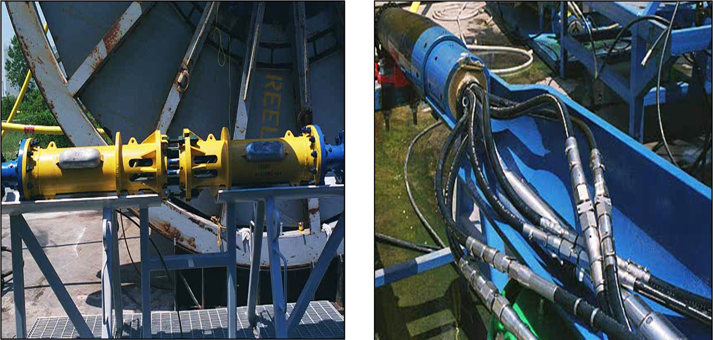
6.4.2.5 Umbilical Splices
Umbilical splices are successfully and routinely used, particularly on very long umbilicals. They must be well designed and correctly installed. If not, they often represent weak points and frequently turn out to be the source of water ingress leading to electrical failures and hydraulic leak points. They can be very reliable, but as a general rule, should be avoided where possible, as they are a potential source of failure. Splices are a useful means of repair to a damaged umbilical, and enable very long umbilicals to be created and installed from shorter flaw free lengths. Unplanned field splices are time consuming to install during an umbilical installation procedure and should be conducted under the close supervision of a representative of the umbilical manufacturer. Planned field spices can be preinstalled on umbilical lengths to minimize field splice make-up time.
Figure 6.13 - Umbilical Splice Connections. Left Photo is a Planned Field Quick Make Up Splice Kit. Right Photo is a Permanent Factory Splice -It Is Similar To a Repair Splice- the Cover is Not Shown on the picture above.
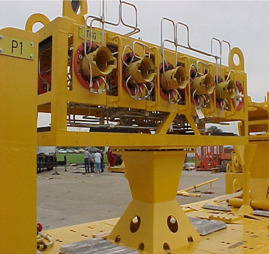
6.4.2.6 Umbilical Termination Assembly (UTA)
The subsea end of the umbilical is terminated with the UTA. The UTA serves to secure the umbilical and provide an interface to connect the umbilical flying leads. It can also serve as an installation aid for lifting and handling the free end of the umbilical and lowering it to the seabed. The UTA often includes a sled-like structure designed for resting on the soft seabed and securing the end of the umbilical. Alternatively it may be in the form of a multibore connector deployed to and directly connected to the subsea manifold.
The electrical and hydraulic flying leads are connected from the UTA to the Subsea Tree, manifold or other end device.
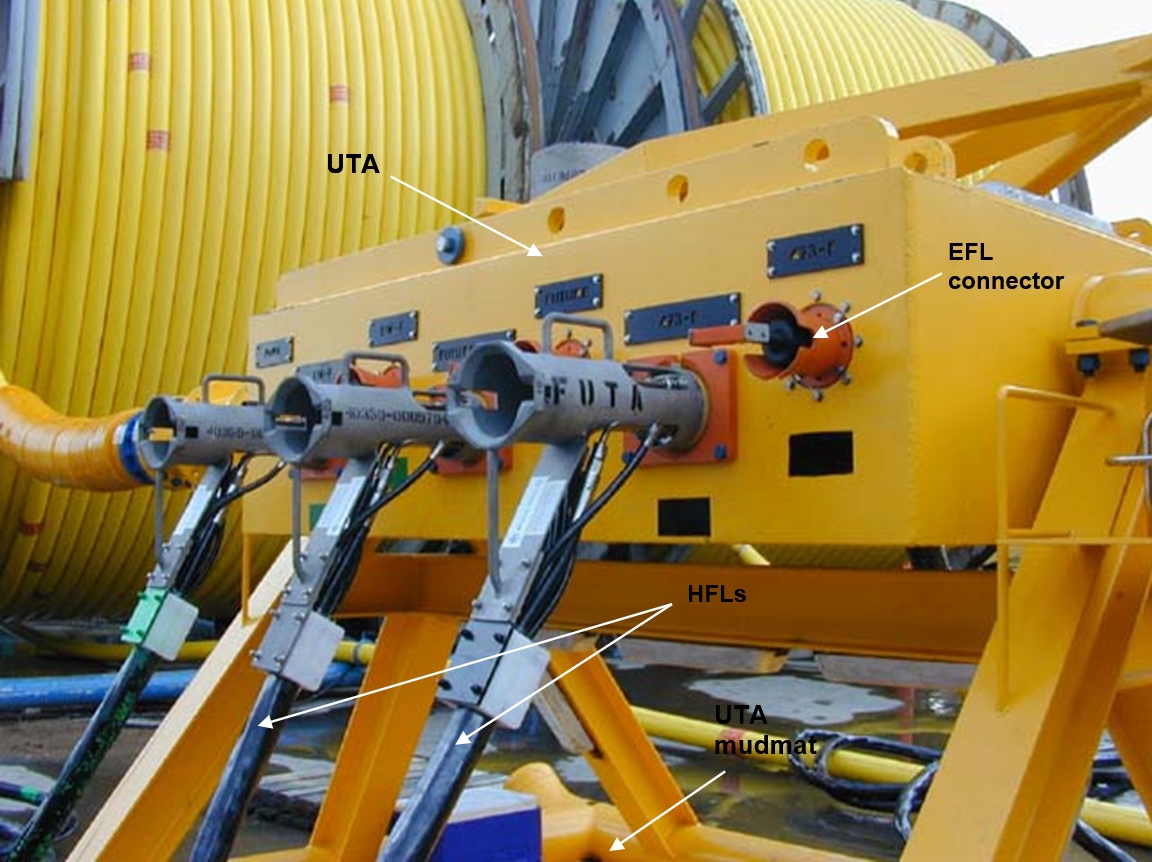
For a complex system the UTA might be broken down into a number of sub-components consisting of an umbilical termination head (UTH), electrical distribution unit (EDU) and the hydraulic distribution module (HDM).
Figure 6.15 - A More Complex Umbilical Termination Assembly for Several Wells –Note the Electrical Connections Are Not Included In This Sub Assembly.
| Tip Click these links below for access to 3D resources: |
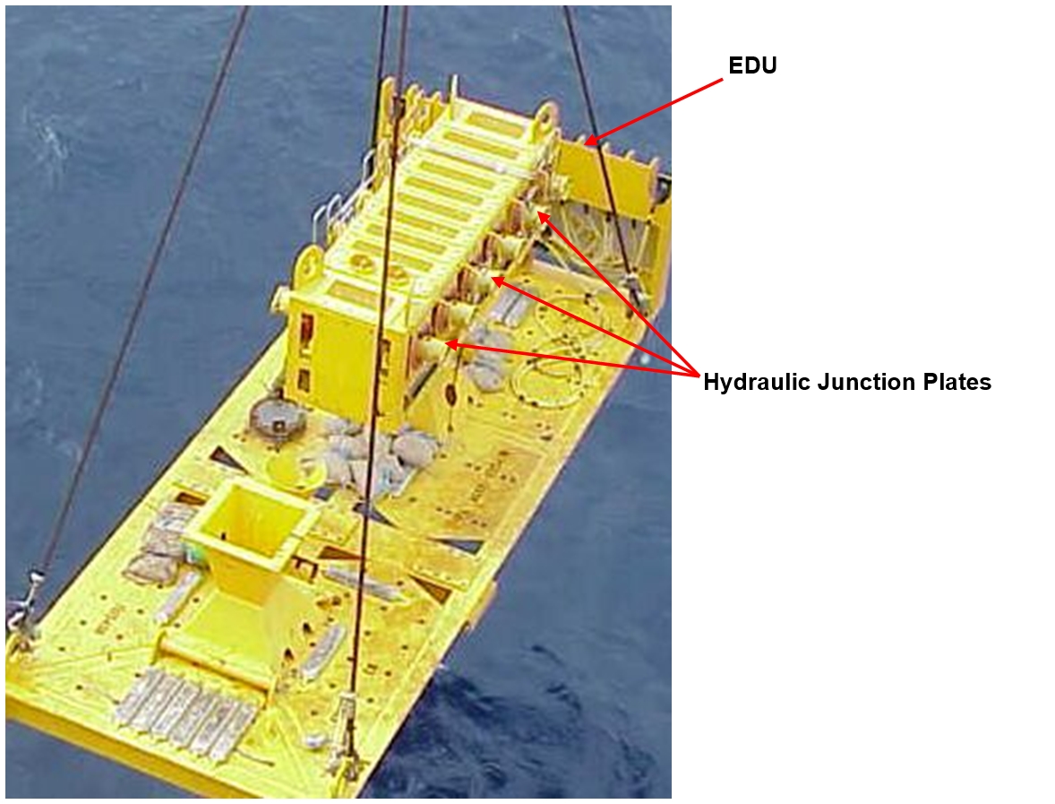
6.4.3 Electrical Distribution Unit (EDU)
The EDU provides electrical distribution to a number of end devices, such as individual subsea trees on a template. The EDU is an oil-filled and pressure compensated enclosure, within which the incoming electrical power and electrical signals are distributed to two or more satellite SCMs. More than one EDU may be chained together, with each EDU serving a number of satellite SCMs.
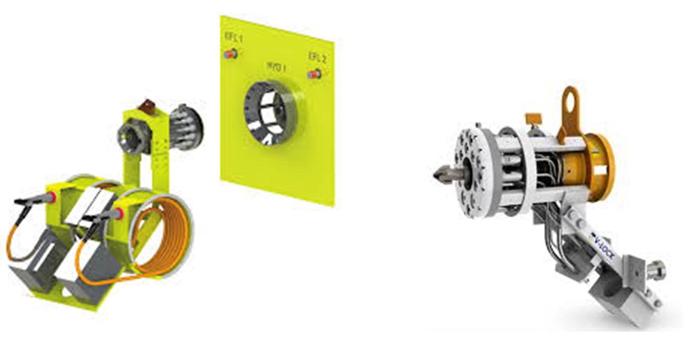
6.4.4 Electrical Flying Leads
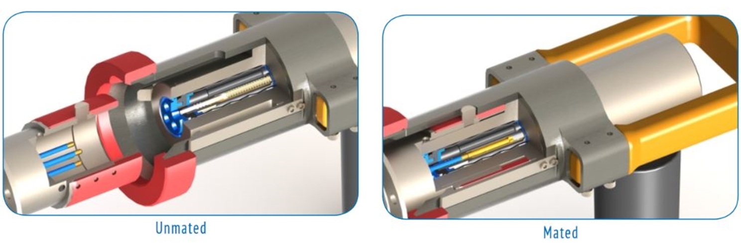
Electrical flying leads (EFLs) provide the electrical interface between the umbilical termination assembly and the Subsea Tree (or other end component). There are often two redundant electrical flying leads from the UTA to the end component. The electrical conductors are usually run inside oil filled hoses. The electrical contacts are protected by dual oil filled barriers. Electrical flying leads are easily installed by ROV. They can be coiled and stowed on the equipment before deployment and uncoiled and installed by the ROV after deployment. Electrical wet mate connectors typically have exposed pins on one half, and protected female contacts on the other half. Subsea distribution systems are usually configured such that if a connection is broken with power on (not recommended), the powered side will be the protected female side, thus shorting should not occur.
Figure 6.17 - Diagram Of an Electrical Flying Lead with Typical ROV Wet Mate-Able Electrical Connectors
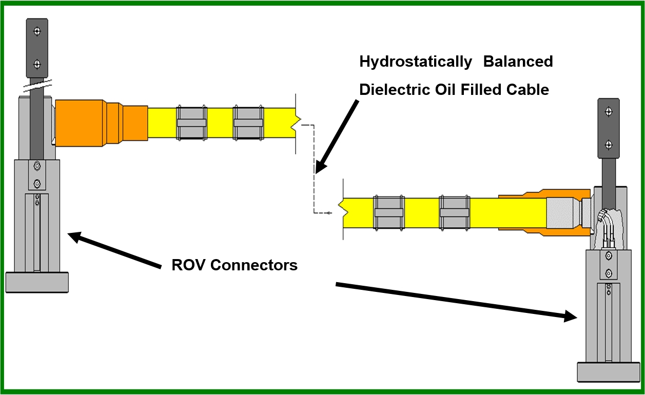
Figure 6.18 - Diagram Of an Electrical Flying Lead with Typical ROV Wet Mate-Able Electrical Connectors
6.4.5 Hydraulic Flying Leads
Hydraulic flying leads (HFLs) provide the hydraulic (and chemical injection) interface between the umbilical termination assembly (or hydraulic distribution module) and the Subsea Tree (or other end component).
The most commonly used and easily manoeuvred hydraulic flying lead is made with thermoplastic hose. The individual hoses are terminated at a junction plate with low force make-up, self-sealing, hydraulic couplings. The hoses are typically constructed with Nylon 11 liner material, braided Kevlar® reinforcement and two outer layers of extruded thermoplastic material. Monel® hose end fittings are permanently swaged onto the hose.
For deep water applications a new high collapse resistant hose has been developed. High collapse resistant hose is steel reinforced to prevent the collapse of the hose in deepwater. The flying leads are stiffer than those of Kevlar® reinforced hose, but can be deployed in a similar manner.
Another type of hydraulic jumper is the steel flying lead (SFL). The steel flying lead is a bundle of steel alloy tubes terminated into couplers on a junction plate. Most designs use super duplex stainless steel material for its high strength. This allows thin wall construction for flexibility. Even so, the steel flying lead is stiffer than the thermoplastic flying leads. Deployment may require additional tooling besides just the ROV. Various deployment kits exist to lay the steel flying lead like a small umbilical. Once the lead is deployed, the ROV can complete the end connections.
6.4.6 Hydraulic Junction Plates
The hydraulic flying lead connects at either end by means of hydraulic junction plates (also called stab plates). Junction plates consist of two halves, one on the flying lead, and a mating half on the other component (Subsea Tree, manifold, umbilical termination assembly, or hydraulic distribution module).
The junction plates (also called MQC plate or RIMS stabplate) on the hydraulic flying lead are designed with ROV buckets so an ROV can connect to them, disconnect them from their pre-deployment “parked” position, manoeuvre them into position for connection to their mating connectors, and effect the connection, usually by means of a rotary torque tool which drives the two junction plates together and effects the mating of the individual hose coupling halves on each junction plate. Junction plates often employ low force couplings that can be mated under pressure, though balancing of forces may have to be considered in such a case. The coupling seals are typically on the recoverable half of the junction plate (i.e. the flying lead).