5 Manifolds and Connection Systems
The function of the Subsea Production Manifold system is to gather and distribute production through an arrangement of piping and valves. Manifold systems may be in satellite / cluster configuration where wells are connected to the manifold via rigid or flexible well jumpers, or may be in template configuration, where the manifold systems includes guides for well installation, and XTs are connected directly to the manifold.
In both cases, the manifold system is typically made up of a foundation structure and a separate manifold module. Where overtrawlability is required, a separate structure may be installed over the manifold or the manifold can be installed inside of overtrawlable template (Laggan Tormore field).
![[Tip]](tip.png) | Tip Click these links below for access to 3D resources: |
5.1 Manifold Module
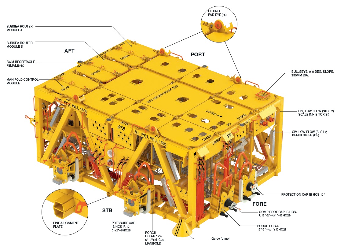
The manifold module contains the functional elements of the system. Some specific functions are:
To collect the flow from individual wells into production header(s) and control the delivery of the commingled flow to a field production gathering flowline(s).
To collect the flow from several field production gathering flowlines and deliver that flow to a larger production export pipeline.
To isolate the production from individual wells and deliver it to a well test header or a well test flowline.
To segregate high pressure and low pressure production into separate high pressure and low pressure headers and flowlines.
To control the flow from individual wells by means of subsea chokes. Wells may be choked at the trees or at the manifold.
To distribute control system hydraulic and electrical supply from a main umbilical to the wells.
To provide points for injection of chemicals into the production fluid, and to distribute chemicals to the production wells.
To distribute injection water or gas from a common supply header to individual injection wells (water injection or gas injection manifolds).
To distribute lift gas from a common lift gas header to individual wells (may be part of the production manifold, or a separate lift gas manifold).
To facilitate pigging of subsea pipelines by provision of pig loops, pig isolation valves, tees and pig detector instrumentation mounted on the manifold piping.
To provide ROV or installation tool interfaces for installation of flowlines, chokes, pig launchers, pig receivers and other components.
To provide protection to the piping and instrumentation from dropped objects and snagging loads.
To facilitate expansion of the field through tie-in points for additional wells or flowlines from other fields.
5.1.1 Piping
The production piping is typically designed as per ASME 31.3, 31.8 or some equivalent. Piping materials are typically carbon steel, duplex or Inconel clad carbon steel depending on the service. Piping is routed to avoid possible water accumulation leading to hydrates, and, where practical, to encourage drainage towards the flowline.
The design pressure of the manifold must be carefully considered. The simplest approach is to match the shut-in pressure of the wells. If this is impractical due to cost, then there needs to be careful consideration to overpressure protection, by assuring proper valve shut-in sequences, valve failure positions and pressure relief at the host production facility (topsides).
5.1.2 Valves
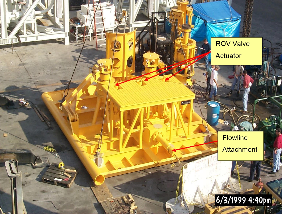
The individual flowline branch valves employed on subsea manifolds are often identical to the types of valves used on subsea Christmas trees. Larger header valves may be specially designed for manifold service. Ball valves developed for subsea pipelines are often used in the larger sizes. Valves used for subsea manifold service are typically designed, fabricated and tested in accordance with API 17D, API 6A and API 6D.
Subsea valves are typically furnished with manual (ROV) actuators or hydraulic actuators. For critical service the hydraulically actuated valve may have a ROV override. All valves should have a visual position indicator.
Manifold valve service is usually less critical than for subsea tree service, in that a small amount of valve leakage may be tolerable. Also, manifold valves may be designed to fail open, whereas Subsea Tree valves are nearly always designed to fail closed. A combination of fail open and fail closed valves may be provided in the manifold piping so that a control system failure will allow production to continue uninterrupted in a safe mode and/or flowline pressure management – typically for hydrate prevention after a shut down. Large valves may have double acting actuators that fail “as is”.
Manifold valves are usually full opening. Header valves often must be piggable and the bore must be smooth and may have to be closely matched to the inside diameter of the flowline and header piping.
The manifold valves and the actuators must be designed for high hydrostatic pressure in deep water service. Hyperbaric testing is recommended. Pressure balanced actuator designs help to mitigate the effects of hydrostatic pressure, but testing is essential to identify unanticipated effects on seals, unrecognized leak paths and such.
Subsea Tree valves rated for 10,000 psi are commonplace. As more subsea trees are designed for 15,000 psi, high pressure valves in smaller sizes will become more available. High pressure valves (20,000 psi) in larger sizes are in development. Availability of valves in the required pressure rating needs to be considered when conceptually planning the manifold performance requirements.
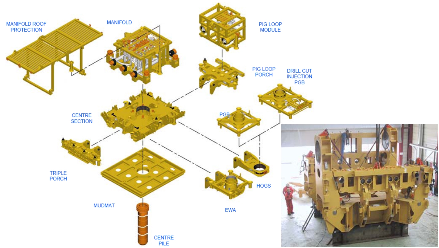
5.2 Manifold Foundation
The function of the foundation is to provide a stable, relatively level, base to support the manifold module and installation, tie-in and flowline loads. The foundation may itself be split into two separate structures to allow for subsea levelling, reduce weight of each lift etc.
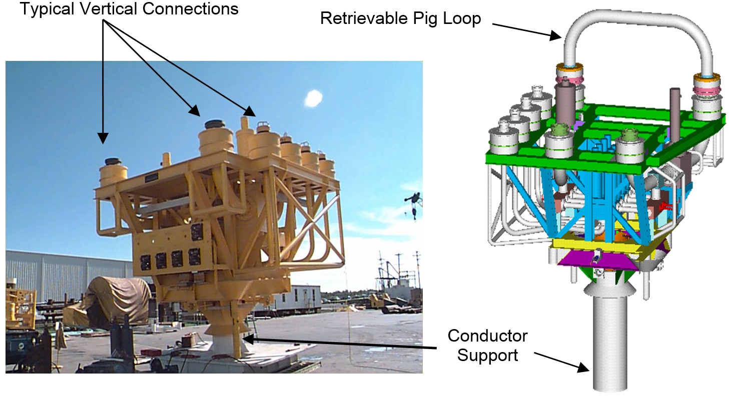
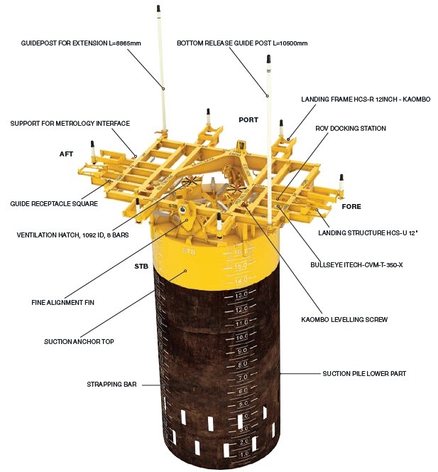
Soil shear strength is a measure of the softness or firmness of the bottom. It indicates the ability of the seabed to support the load of the template or manifold. The type and size of the foundation is dictated by the load bearing capacity of the soil. In deep water applications, the soil properties typically dictate a piled foundation. There are a number of common piled foundation designs including single central suction anchor, multiple suction anchors (spud cans) attached to common frame, and drilled and grouted or jetted central conductor. In the case of a single central pile, a levelling structure may be required.
For cluster manifold systems, where horizontal connection systems are used (see below), the foundation structure may also include the guidance systems for the connectors. This allows the connectors to be disconnected and stroked back and left in position, in the event of a manifold retrieval being required.
For template manifold systems, the foundation structure includes guidance systems for the well conductor housings to control the relative position of the XTs and the manifold module. Once installed, the well conductors may contribute to the foundation of the template.
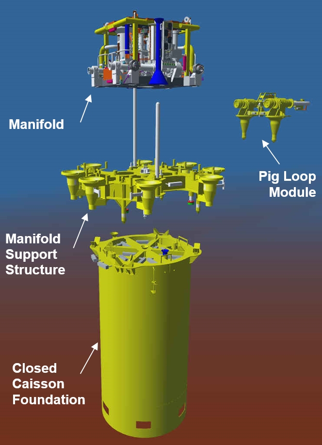
5.3 Manifold Protection Structure
Typically for deep water developments, impact protection of pressure containing piping and instrumentation from dropped objects is incorporated into the roof of the manifold module. In most deepwater projects, fish trawling is not a design criteria, though there are exceptions to this, particularly as fish trawling also moves into deeper water.
5.4 Template vs. Cluster Manifolds
Both template and cluster manifold systems have been used in deepwater applications. Many of the pros and cons are project specific, some factors to be considered when selecting template vs. cluster manifold systems are as follows:
5.4.1 Installation Vessel Requirements
The vessel requirements for installation of a template foundation, compared with a cluster manifold foundation are typically more onerous. However, modular template structures exist which facilitate installation, such as the TECHNIPFMC HOSTTM
5.4.2 Tree to Manifold Connections
This is the main differentiator between template and cluster systems. In the case of a template system, the connection may be made by the drilling rig following XT installation (assuming the manifold is installed before drilling). The connection could be operated remotely via the WOCS, or by ROV deployed from the drilling rig. Thus the operation is a short duration and / or parallel activity.
For the cluster system, metrology is required between the position of the tree and the manifold to determine the required well jumper dimensions. Following this, well jumper fabrication is performed onshore, and the jumpers installed by an installation vessel.
The jumpers are designed to provide flexibility to accommodate fabrication tolerances, metrology inaccuracies, jumper thermal expansion (for production only), connector stroking, connector axial/radial/angular misalignments, displacements of tree and manifold due to external loads etc. The jumpers therefore may be long and of complex shape, thus handling and installation of these jumpers can be a difficult and time consuming task. Furthermore, coordination of rig vs. installation vessel activities is required.
5.4.3 Damage and Protection of Installed Equipment
In a template system, due to the close proximity of all SPS equipment, the probability of a dropped object striking an adjacent wellhead, XT or manifold is higher, and the consequences of a single dropped object impacting the subsea facilities is likely to be greater.
To maximise the schedule, production operations commence while the drilling program is ongoing. In the case of a template system, the manifold and other SPS equipment is in place throughout the drilling program. This results in these items being exposed to vibration damage.
The template system offers the opportunity to provide protection from dropped objects by installing a separate structure over the entire system, rather than separate structures over the manifold and each well.
5.4.4 Flow Assurance
For the template system, the cooldown time may be slightly longer due to slightly higher starting temperature (reduced heat loss compared with a long well jumper during production). In addition, preservation of well jumpers is not required, so methanol injection volume is reduced.
5.4.5 Future Tie-Ins / Contingency for Well Re-Spud
In both systems, additional slots can be allocated. However, the cluster solution provides greater flexibility for tie-in of future wells through piggy back with existing wells in the cluster. Well re-spud does not consume a slot in the cluster configuration.
5.5 Connection Systems
The function of the connection system is to allow subsea remote connection of production, injection, chemical and control system functions between the infield flowlines and umbilicals, and the SPS system, and between the SPS packages (refer to for further details).
For tie-ins between flowlines and manifolds or satellite wells, the flowline is commonly furnished with a Pipeline End Termination (PLET) that consists of a sled-like structure on the end of the flowline supporting the end fitting and sometimes a pipeline valve or small manifold (PLEM). The final connection to the manifold or tree is accomplished with a jumper.
Alternatively the flowline may be directly connected to the manifold structure where flowline loads are within the capacity of the manifold system. In this case, the flowline may be initiated at the manifold (first end) and laid away. The flowline connector is then pulled in to the manifold and connected by a dedicated ROV tool.
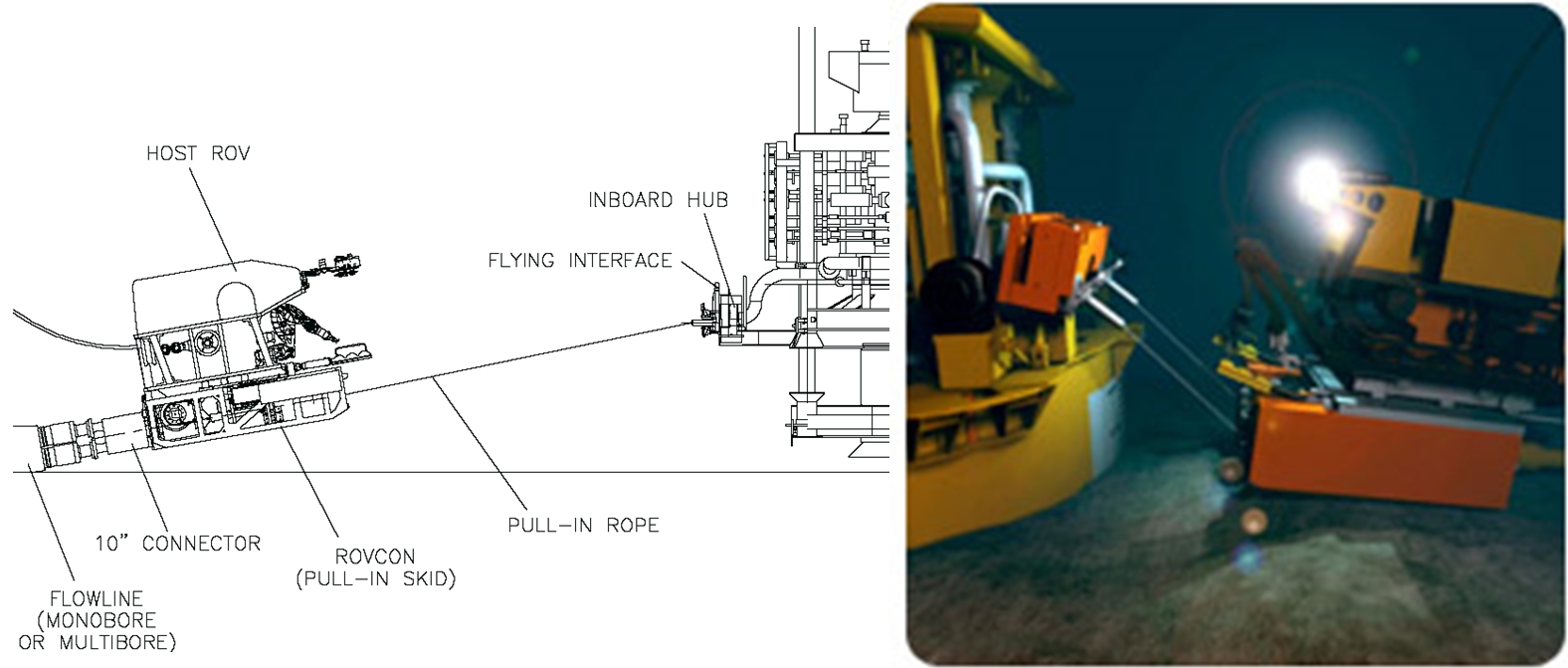
Where bottom conditions are difficult, an alternative is to deploy the flowline connector directly to a receptacle on the manifold structure and then lay away. The connection is made by a dedicated ROV tool.
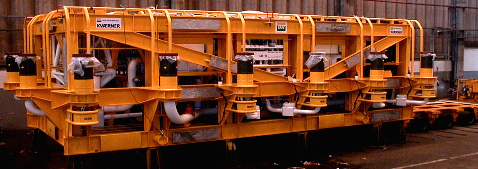
For tie-ins between manifolds and local wells (cluster arrangement), connections are typically made by rigid or flexible jumpers.
Connectors may be mono-bore or multi-bore, in horizontal or vertical orientation, and utilise collet or clamp type connectors. Each of these options is discussed in the sections below.
5.5.1 Mono-bore vs. Multi-bore
A mono-bore connector is used to make a single flowline connection only. Ancillary lines, e.g. hydraulic, chemical and service lines are typically contained in one or more separate flying leads which are connected to the manifold and XT by ROV stab-plates. A multi-bore connector simultaneously connects multiple flow paths. E.g. production, hydraulic, chemical and service lines running from a manifold to a production XT are bundled together and connected via a single multi-bore connector. Multi-bore connection sealing is performed by a single, ROV replaceable seal plate.
Electrical connections are not usually made simultaneously, though electrical flying leads can be piggy backed to the well jumper, with connections at both ends being made up separately by ROV manipulator.
The multi-bore system requires that hydraulic distribution is an integral part of the manifold system, thus repair of the hydraulic distribution system requires retrieval of the entire manifold. For a mono-bore system, all hydraulic distribution can be located on a separately retrievable subsea distribution unit. However, the mono-bore system implies higher installation vessel duration and cost.
5.5.2 Vertical vs. Horizontal
Tie-in systems are called “horizontal” when the connectors at both ends of the spool are positioned in the horizontal plane. Horizontal spools can be either laid on the seabed and pulled in to the subsea structures, or deployed directly to the subsea structures (docked on both structures, or stab and hinge over arrangement). ROV operated tooling is used to perform the connection.
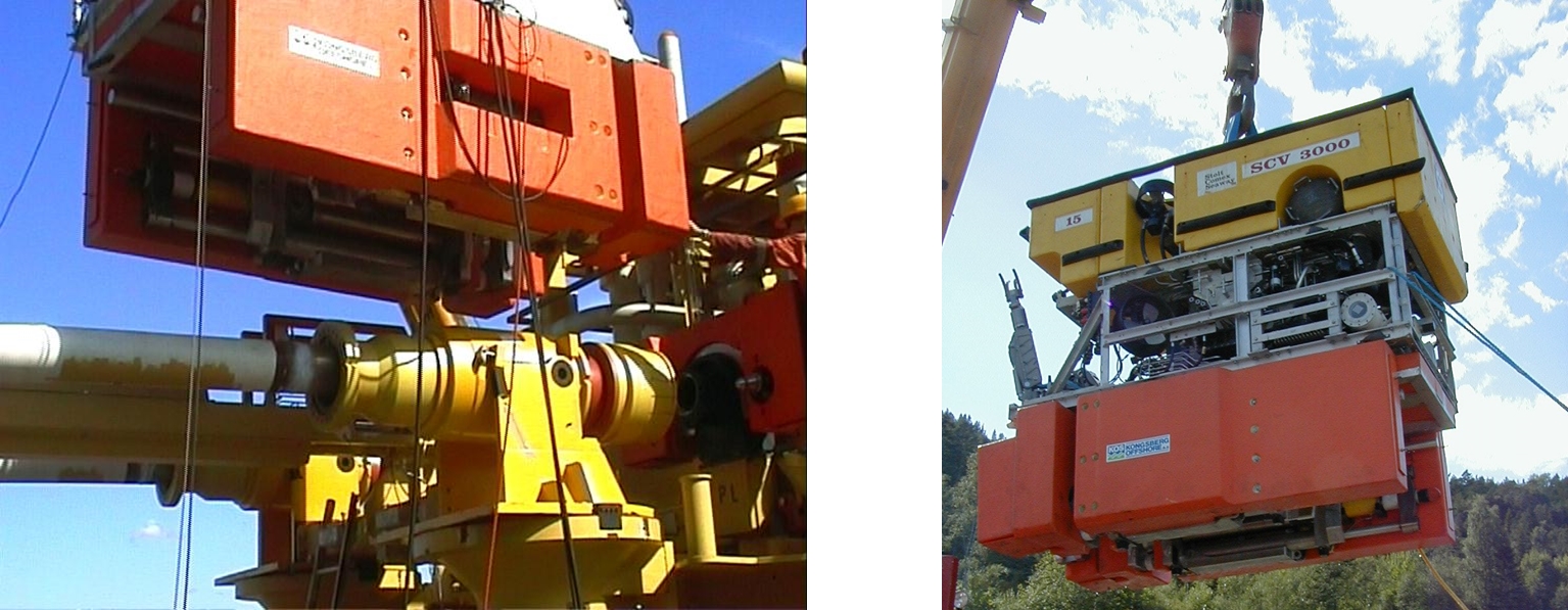
A typical ROV mounted ‘connector actuation tool’ (CAT) (used for TECHNIPFMC Stabcon horizontal connector) is shown in the figures below:
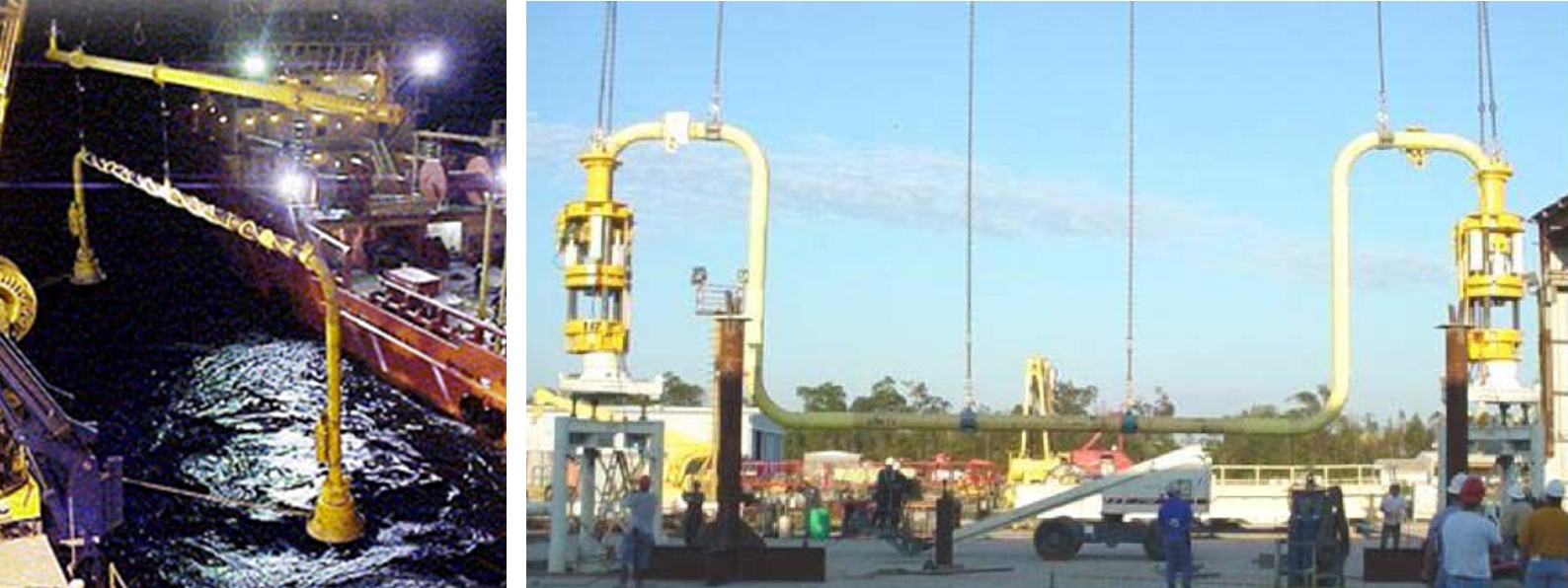
Tie-in systems are called “vertical” when the connectors at both ends are positioned in the vertical axis. Vertical spools are typically deployed directly and stab onto the subsea structures. The following figures show different configurations of vertical spools. Vertical tie-in system principle considerations are discussed in the following sections.
Figure 5.9 - Various vertical connection jumpers (by courtesy of OneSubsea (left) and OneSubsea/ Nexen Petroleum (right))
For recovery of a XT or manifold, vertical connections must be broken, and well jumper, flowline or umbilicals recovered to surface, or moved to a separate parking structure. With horizontal connections, the connectors can be disconnected and stroked back allowing the module to be retrieved. This is an important factor in the selection of the connection system, and the significance of this advantage depends on the likely frequency of recovery of modules. E.g. vertical XTs are more likely to require retrieval as they need to be retrieved for any tubing workover.
The advantages of vertical vs. horizontal connections are generally related to simplicity of drill center layout, ease of fabrication / transportation of well jumpers and ease of installation and connection.
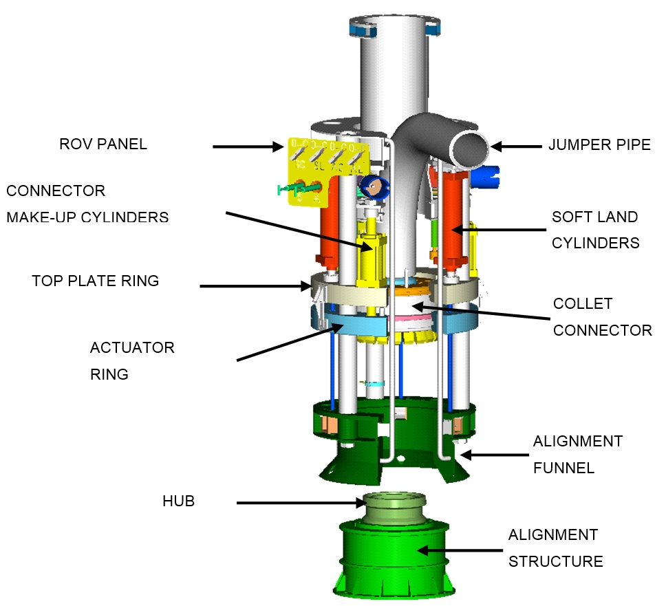
5.5.3 Connector Type
The purpose of the connector is to provide a structural connection, to establish a metal-to-metal seal, and to provide sufficient pre-load and stiffness to withstand applied loads and moments without separating the hub faces. The connector should not be the weak link in the tie-in system. I.e. the connector should be stronger than the spool pipe, and stresses in the pipe should always govern tie-in spool dimensions. Connection systems should allow for seal integrity (external tie-in leak) test to be performed prior to recovering installation tools. In the event of a seal failure, it should be possible to retrieve and replace the seal remotely – i.e. without recovering the entire spool to surface. The various diverless connection systems currently used are described in the sections below.
5.5.3.1 Collet Connector
The figure below shows the collet fingers and seal plate for the horizontal multi-bore connector used for Girassol production well jumper connections.
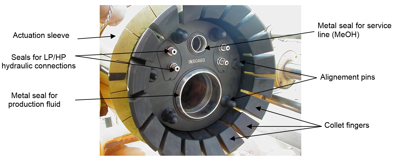
The connector is operated closed by driving an activation sleeve axially along the tapered outside diameter of a segmented collet finger set, driving the collet fingers radially inwards against a mating hub outside diameter profile, and drawing the two mating hub faces together. The activation sleeve may be operated by an integral or removable tool.
5.5.3.2 Clamp connector
Two basic designs of clamp connectors have been used in subsea applications. These are 2-piece and 3-piece clamps, where the number refers to the number of clamp segments. A 2-piece design (with multi-bore seal plate) is shown in the figure below:
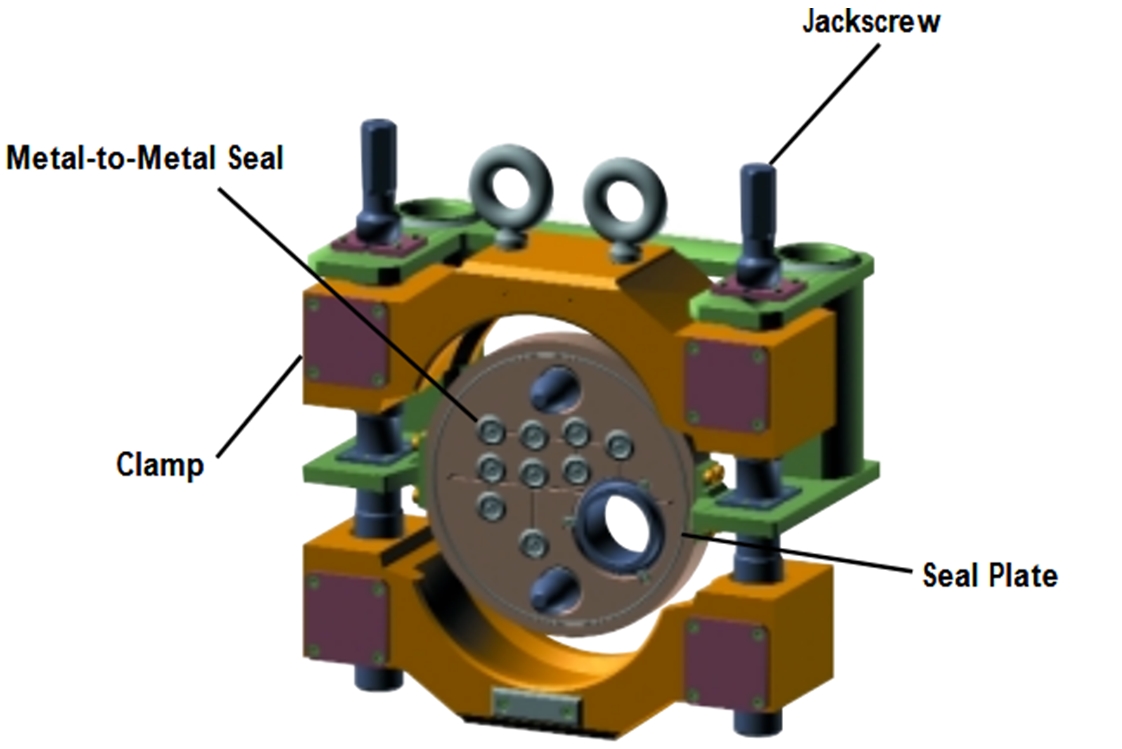
The connection is made by pulling in the mating hubs to the seal plate and tightening the jackscrews will: (a) drive the clamp segments against a tapered profile on the outside diameter of the hub, (b) pre-loading the connection and energizing the metal-to-metal seal.
A 3-pieces clamp design is shown in the figure below.
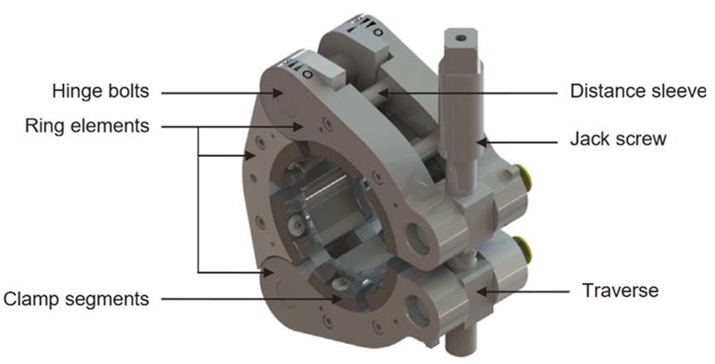
The hinged clamp segments are designed such that the connection is made by operation of a single jackscrew. Design of the clamp elements should allow even application circumferentially around the hub face as the connection is pre-loaded. In some designs, the jackscrew length is sufficient to allow the clamp to be opened such that the connector (and seal ring) can be retrieved or installed without any of the clamp elements passing between the hub faces.
5.5.3.3 Others systems
Various configurations of mandrel connectors exist, which are based on the principle of driving a split ring or dogs into a groove using an activation sleeve in a similar manner to the collet connector. These connectors are not widely used for flowline or spool tie-in.
API standard flanges can also be used, although tooling to make these connections remotely is more complex. The MATIS tool (Acergy, now SS7) was used to perform flanged connections on the Girassol Field.