
7 General SPS Design Considerations
In this section, those subjects which relate to design and operation of deepwater Subsea Production Systems, and which are common across the main equipment categories, are addressed.
7.1 Corrosion and Erosion Design
Considering the high cost for intervention, material selection becomes more critical for deep-water applications. Investment in the right materials will prevent or mitigate the likelihood of equipment failure due to corrosion / erosion mechanisms. The most common corrosion and erosion mechanisms which can cause deterioration of SPS equipment are:
7.1.1 Corrosive Agents
7.1.1.1 Hydrogen Sulphide
Hydrogen sulphide in even low concentrations can induce cracking in wrought materials, wherein nascent hydrogen ions produced by other corrosion activity at the metal surface do not recombine to gaseous hydrogen due to the action of sulphide ions. The H+ ions migrate through the metal recombining to H2 at discontinuities, creating very high pressures and causing the metal to crack.
Another failure mechanism induced by hydrogen sulphide at higher levels is sulphide stress corrosion cracking. Sulphide stress corrosion failures tend to be catastrophic in nature because the effects are more pronounced on more highly stressed areas. The failures commonly occur in the heat-affected zone adjacent to welds.
The measure of H2S concentration level is partial pressure. Low concentrations at high pressure are equivalent to higher concentrations at lower pressure. The effects are further influenced by temperature, but generalities do not apply well. For some materials the susceptibility to stress corrosion cracking decreases with increasing temperature. For others it may increase to a point and then decline. The presence of other corrosive agents such as chlorides may also have an effect on this behaviour.
Extensive testing of metal alloys by the National Association of Corrosion Engineers (NACE) has demonstrated that by controlling material hardness and microstructure the effects of stress corrosion can be mitigated. Guidelines are published in NACE MR - 01- 75. The European Federation of Corrosion, Oil and Gas Working Parties have also issued guidelines for H2S service for both plain steels and corrosion resistant alloys (CRAs). These present more detailed guidelines than the NACE document and are complementary to it.
7.1.1.2 Carbon Dioxide
Carbon dioxide in the presence of water forms carbonic acid which corrodes low alloy steels. The principle indicators to watch for are partial pressure and temperature, with corrosion rates increasing with the increase of either the temperature or the partial pressure. Above 60°C a protective deposit of iron carbonate is formed on the surface of low alloy steels that inhibits the corrosive effects of CO2. Any areas not so protected, due to a feature of operation that prevents the formation of this carbonate product or disrupts it, will continue to experience high corrosion rates.
Much work in the field of CO2 corrosion has been conducted by DeWaard and Milliams [Simom-Thomas MJJ, DeWaard C, SmithLA: “Controlling Factors in the Rate of CO2 Corrosion.” UK Corrosion 1987].
7.1.1.3 Chloride Ions
Chloride ions, present in the formation water of the reservoir, can cause cracking and pitting in certain materials. The cracking mechanism is chloride stress corrosion cracking, in stressed areas above 50°C. This corrosion mechanism is largely independent of pressure. Austenitic stainless steels, such as type 316, are susceptible. Low alloy steels and martensitic stainless steels (F6NM) are less susceptible to chloride induced stress corrosion cracking, but suffer from pitting corrosion.
7.1.1.4 Crevice Attack and Pitting
Crevice attack and pitting are very common forms of corrosion in seawater.
Pitting is caused by local concentration cells set up by differences in oxygen concentration, temperature, or fluid velocity. It is more prevalent under relatively stagnant conditions. Surface features or metallurgical factors, such as inclusions, breaks in the protective film, surface defects, etc. may help initiate pitting.
Crevice corrosion occurs around gaskets, washers, fasteners, foreign matter, etc. that provide crevices that can become oxygen deprived. Crevice effects may be enhanced by simultaneous galvanic action. Elastomers containing sulphur or graphite are especially damaging to stainless steels.
7.1.1.5 HISC
Hydrogen Induced Stress Cracking (HISC) has occurred in duplex or super duplex components exposed to high levels of stress while exposed to cathodic protection. Failures have been attributed to hydrogen embrittlement caused by ingress of hydrogen formed at the steel surface due to the cathodic protection.
Measures to prevent HISC occurring include:
Checking piping stress analysis against HISC criteria given in various industry guidelines, e.g. DNV RP F112.
Use of qualified material suppliers and fabricators to ensure quality of the material (fine grain structure is considered to be less susceptible to HISC than coarse grain structures).
Maintaining Cathodic Protection potentials lower than typically –850mV.
Avoid overprotection (cathodic potential less negative than -1100 mV)
Attention to coatings on duplex and super duplex materials to minimise risk of contact of hydrogen ions with metal surface.
7.1.2 Erosion
Erosion is a physical process, whereas corrosion is usually a chemical process. Apart from the direct loss of material from erosion effects, erosion often accelerates the rate of corrosion by preventing the formation of protective films or scale and exposing new metal to the corrosive environment.
The worst erosion agent is sand in the produced fluids. It is impractical to design against high levels of sand production so sand control and monitoring is critical.
There are several design features that can mitigate erosion effects.
Large flow passages to reduce velocity.
Long radius piping bends.
“Cushion” tees.
Overlay with harder and/or more corrosion resistant materials in susceptible areas.
Extra material thickness in susceptible areas.
There is instrumentation available to monitor sand production and material loss. Acoustic non-intrusive sand detectors are typically employed to give the operator first indication of sand production. The operator can “tune” the rate of opening the choke, and optimise the production rate while avoiding sand production.
The first defence is prevention of sand production through careful design and deployment of well completions with sand screen. If that fails, the tree mounted sand detector may detect the problem before it becomes catastrophic.
7.2 Materials Selection and Corrosion Protection
7.2.1 Low Alloy Steels
Where suitable, low alloy steels are desirable because they are inexpensive, easy to weld and readily available. The low alloy steels are carbon-manganese grades, in accordance with API or ASTM standards (e.g. AISI 4130 & 8630). Low alloy steels, however, are limited in their usefulness in corrosive service.
For CO2 corrosion it is generally accepted that when the CO2 partial pressure is above 0.5 bar significant corrosion may occur in low alloy steels and their use is not recommended. Low alloy steels may be used in CO2 service if the wetted areas are clad with a protective overlay of corrosion resistant material such as Inconel or stainless steel.
H2S induced stress corrosion cracking is a concern with low alloy steels where H2S partial pressure is above the allowable level. It can be mitigated, however, by controlling the material grain structure and hardness.
7.2.2 Martensitic Stainless Steels
Martensitic grades of stainless steel (ASTM A182: F6NM, AISI 410) offer good resistance to both carbon dioxide and hydrogen sulphide. They have low resistance, however, to pitting corrosion due to chlorides, especially at higher temperatures. Extended exposure to high chloride environments may result in severe localized pitting, particularly where natural crevices exist.
These steels are available in high strengths and are widely used in down hole and wellhead applications.
7.2.3 Austenitic Stainless Steels
Austenitic stainless steels (e.g. AISI 316 L) have excellent corrosion resistance up to 50 bar partial pressure of CO2. However, chloride stress corrosion resistance is limited to operating temperatures up to 50°C. They can be susceptible to crevice corrosion. Austenitic stainless steel is immune to sulphide stress corrosion cracking up to 0.5 bar partial pressure of H2S at temperatures up to 60°C.
The low yield strength of austenitic stainless steels renders them unsuitable for structural components but they are extensively used for fittings and connectors. They are particularly suited for gasket materials where their low yield ensures that they deform preferentially to the ring groove and deform readily into any surface irregularities.
7.2.4 Duplex Stainless Steels
Duplex stainless steels are high alloy steels comprised of both austenitic and ferritic phases. The two most commonly specified grades of duplex stainless steels are UNS 31803 (with 22% Cr and 5% Ni), and UNS 32750 (25% Cr, 7% Ni). The 25%CR material is sometimes referred to as “super duplex” or high performance duplex.
Duplex stainless steels offer better resistance to CO2 and chlorides than the austenitic (316L) stainless steels and have higher mechanical strength.
Duplex stainless steels are frequently used for small bore piping and downhole tubing. It is not used for large forgings because of the expense and because of reduced mechanical strength near the center of thick forged sections.
7.2.5 High Nickel Alloys
The high nickel alloys containing 25% to 65% Ni are the most resistant to both CO2 and H2S corrosion. No limits are given for CO2 corrosion, whereas H2S corrosion is a function of the nickel content. Inconel alloys UNS N08825 and UNS N06625 are the most widely used high nickel alloys in the oil industry. They are usually more expensive than the duplex stainless steel alloys.
High nickel alloys are used in both solid forgings and as weld cladding on less expensive low alloy steel substrate. Overlaying the exposed surface with a high nickel alloy can mitigate crevice corrosion effects. This is the case with ring gasket seal areas. It is important that the alloys used for the overlay have hardness greater than the gasket seal material to minimize the risk of locally yielding the ring groove.
7.2.6 Coatings and Cathodic Protection
It is normal to use sacrificial aluminium anodes to protect the steel components of subsea trees, templates, manifolds and pipelines from seawater corrosion. The anodes are usually used in conjunction with a high quality epoxy coating system applied to the low alloy steel components. Stainless steel components are typically left bare. The anodes afford the austenitic stainless steels some protection against pitting and crevice corrosion as well.
The coating helps to minimize the rate of consumption of the anodes, allowing for fewer anodes and extending their life. The anodes must be designed for the life of the equipment and must take into account for degradation of the coating. Replacement of anodes is not an option, or a very expensive one.
The coating system commonly consists of an epoxy primer applied over a surface that has been prepared by cleaning and grit blasting to “white metal”, followed by the application of two coats of high build polyamide epoxy.
7.3 Flow Assurance Considerations
Flow assurance has become something of a catch phrase in the subsea industry, but for good reason. As developments move into deeper water lower seabed temperatures are encountered, increasing the likelihood of flow problems, the means of intervention are fewer, and the costs are higher. While most flow assurance issues are with the flowlines, the mitigation of flow assurance problems may begin at the Subsea Tree, or even downhole. The following are some possible sources of, or contributors to flow assurance problems.
Hydrate formation: Due to low ambient temperature and high ambient pressure, the produced fluid is often within the hydrate region at seabed ambient conditions. In this case, subsea equipment must be preserved by displacing produced fluids with methanol or stabilised oil following shutdown. A “no touch time” is required following a shutdown to allow the operator to re-start, or to initiate and complete the preservation sequence. Subsea equipment may need to be thermally insulated to maintain the produced fluids above the hydrate formation temperature during this time. Other hydrate mitigating factors include careful design of piping to avoid low points where water could accumulate.
Wax deposition. If the seabed temperature is below the wax crystallization temperature (cloud point) deposition of wax on the walls of the flowlines may take place. Local wax deposits could also occur due to local “cold spots” in the pipe wall – e.g. in connectors.
High viscosity, high pour point. Low temperature results in higher viscosity and diminished flow rates.
Asphaltenes. These can precipitate similarly to wax crystals and restrict the flow.
Sand production. Sand can accumulate in flowlines and restrict flow. If any of the other contributors to flow assurance problems are present the problems can be greatly compounded with the additional presence of sand. Sand production can very seriously and very rapidly degrade the pressure integrity of subsea systems.
Scale formation. Scale deposits can restrict flow passages.
There are a number of measures that can be taken to mitigate flow assurance problems. These are described in the following sections.
7.3.1 Insulation
The SPS may be insulated against the cold seawater to minimise heat loss during steady state production operations, and to maintain the produced fluid above the hydrate formation temperature for a defined duration following a shutdown. The latter is usually the governing case.
There are many potential cold spots which require special attention:
Bottom of tree – significant heat can be lost to the well causing rapid cooling of the lower part of the tree, creating the conditions for hydrate formation in the vicinity of the Production Master Valve PMV (vertical tree).
Tree cap, choke, connectors – insulation of these parts must facilitate installation / retrieval / connector, while avoiding thermal bridges.
Intrusive sensors – insulation of sensors must be carefully designed avoid heat transfer from the piping, while not causing the sensor electronics to overheat. For temperature transducers, the insulation design should ensure the sensor reading is representative of the produced fluid temperature.
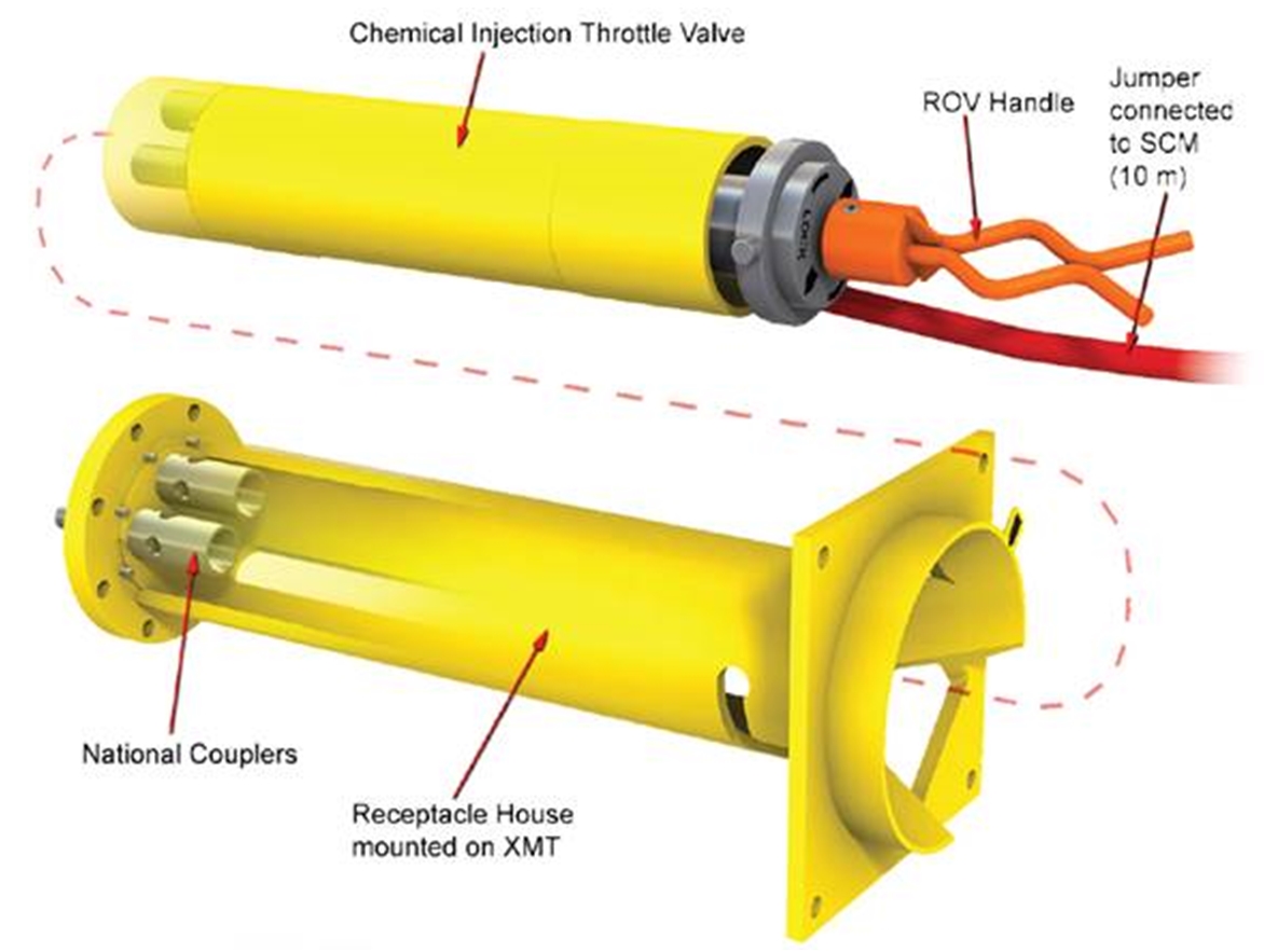
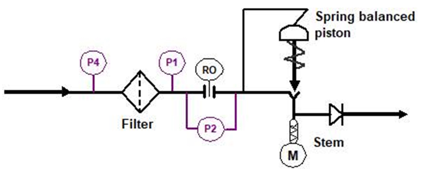
7.3.2 Chemical injection
Wax inhibitor, pour point suppressant, methanol, and scale inhibitors may be injected at the Subsea Tree or downhole. The chemicals are often delivered through tubes in the production control umbilical reserved for that purpose, or through a dedicated umbilical or tube bundle. Actuated injection valves, check valves, and throttle valves are typically provided at the injection point on the subsea tree. Downhole injection requires that the tree and Tubing Hanger be ported, and a downhole injection line installed with the completion tubing string.
Other chemicals like corrosion inhibitor, anti-naphtenates, demulsifier, biocide, Low Dosage Hydrate Inhibitor LDHI can be injected at different location of the production network (downhole, XT, Manifold, at riser base, etc.)
7.3.3 Heating
While not commonly implemented due to cost and technical obstacles, heat tracing of the Subsea Tree and flowline, accompanied by insulation, could be a solution to an extreme flow assurance problem. An alternative may be to circulate hot water within a production bundle, or stabilised crude oil where two flowlines are connected to the production manifold.
7.3.4 Operation pigging
Regular pigging can control the accumulation of wax, sand and asphaltenes. Pigging issues are discussed in more detail elsewhere.
7.3.5 Subsea Processing
Subsea processing systems have been developed in recent years to allow a range of processing operations to be performed close to the wellhead, and even downhole. Subsea pumps have been used for a number of years on a relatively small number of projects. More recently, subsea multiphase pumps have been developed. Subsea separation systems using gravity or cyclone separation system technology have been developed, and these can be applied in combination with subsea pumps to separate out the produced water and re-inject it. This can allow reduced flowline sizes, potentially reducing project costs.
For more information on Subsea Processing please refer to Reference book :[137].
7.4 Deepwater Design Considerations
Deep is a subjective term, but as developments move into ever deeper water those issues that have always posed challenges to subsea engineers become even greater and the solutions that worked successfully before no longer suffice. It is the designer’s challenge to identify where to apply new solutions while building on what has worked in the past. The following are some deep water design challenges:
7.4.1 High Hydrostatic Pressures
High hydrostatic pressures can sometimes have unexpected effects on equipment. The following are some things to consider.
If pressures are not balanced, the hydrostatic pressure can force parts together or apart with unexpectedly high force, causing seizure or failure.
Hydrostatic pressures can collapse elastomeric seals, hoses and other soft components.
Spring return actuators may be affected, causing valves to open or close unexpectedly.
Umbilical coupler seals may allow seawater intrusion, or junction plates may become impossible to disengage.
High pressure could be trapped inside equipment that has been exposed to great depth and could present a hazard to personnel on the surface when the equipment is retrieved.
Hydrostatic differentials due to differing specific gravities of different fluids can cause inadvertent reactions. These can include “U-tubing” of fluids into umbilical hoses or hydraulic function of a running tool or device where the control fluid or chemical in the umbilical hose is a lighter fluid than the ambient sea pressure or completion brine in the marine drilling riser and well.
7.4.2 Equipment Guidance
The long vertical offset complicates the station keeping for the drilling rig and makes the use of guidelines impractical. The following are some considerations.
Guide funnels to capture devices and guide them into position.
Fenders and guard rails to protect other equipment from damage.
Soft landing cylinders. These allow rough engagement and capture of a component (e.g. a vertical flowline connector) without risk of damaging seals, and then a hydraulic mechanism controls the movement from there to the final position.
7.4.3 Low Temperatures
Extreme low temperatures can result from gas expansion (e.g. across a choke) combined with the low ambient seabed temperatures. Besides the flow assurance issues addressed above, low temperatures may have other effects.
Increased stiffness of elastomers. Elastomer material selections may have to be reviewed, or metal seals employed.
Thermal stresses due to high temperature differential or temperature changes. Clearances may be affected. Flexibility of piping loops may have to be addressed.
Material embrittlement. Low temperature material may have to be specified and Charpy notch toughness testing conducted.
7.4.4 Long Trip Times
Drilling and completion operations require numerous round trips to run and retrieve the various components and running tools. The time required for each operation increases with the water depth. In addition, the day rate cost is usually higher for deep water drilling rigs. Finally, the risk of a mishap with each trip increases with increased water depth, due to longer exposure times and less precise positioning control. The designer may address this by finding ways to minimize the number of trips required. The operator may address it by carefully planning all completion procedures.
7.4.5 Diverless Installation / Remotely Operated Vehicles
7.4.5.1 General
All completion operations must be conducted without the benefit of diver intervention. Diverless tree technology is well developed and Remotely Operated Vehicle intervention tooling is pretty well adapted to supporting subsea completions.
Remotely Operated Vehicles, commonly referred to as ROV’s, are remotely controlled unmanned submersible robots – submarines. They are available in a variety of capabilities and sizes. The most basic ROV is merely a camera carrying vehicle with thrusters to drive it to location under water. Larger work class ROV’s include many cameras, manipulator arms with a variety of capabilities, numerous thrusters, sonar, and other sensors. They are available with a variety of different depth ratings.
ROV’s are controlled from a central computerized control room – often nicknamed the ROV shack – with power and control signals passing through an umbilical to the vehicle. The umbilical stays permanently attached to the ROV. The deeper classed systems include a powered diving cage and tether management system to reduce current drag on a long umbilical system from the surface vessel.
ROV’s can perform a wide variety of functions underwater. The only constraint is that most functions must have been pre-designed for ROV interfacing before the equipment is installed subsea. In addition to the manipulator and gripper functions, ROV’s can easily be equipped with special additional and often standard tool packages. These are designed to interface with the equipment being installed subsea.
ROV interface is a system level issue as it affects almost all work packages and certainly all of the subsea installation, workover and intervention activities. ROV interfaces on subsea equipment have been standardized and most operators specify ROV interface design to be in accordance with ISO 13628-8.
For more information ROVs and associated tools refer to Offshore Reference Book Deepwater ROV & Tools .
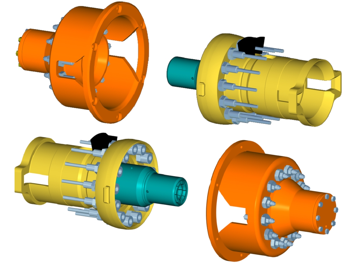
Figure 7.3 - Typical subsea mated junction plates with hydraulic couplings, where the inboard plate contains the male couplers and is permanently mounted. The outboard plate contains the female couplers and the ROV bucket for installation interface.
7.4.5.2 Types of Interface
There are several different categories of tools that a standard working ROV will use to interface with subsea equipment. These include:
Torque tools: There are five ranges of torque settings for overriding or mating of components subsea. For each torque range is assigned a Class rating per ISO 13628-8.
Linear Override: The interface which may be used to push directly on an actuator stem to override the valve open / closed.
Manipulator – Depending on how an ROV is outfitted, it may have a variety of “arms” for handling purposes outfitted with a variety of end “hands” called grippers. ROVs sometimes are equipped with one but more often have two manipulators, one which is a five function manipulator (left manipulator), and the other with seven functions (right manipulator).
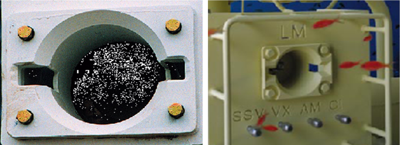
Figure 7.4 - Standard ROV torque buckets - the end effector inside the bucket is difficult to see in these photos. The end effector size and shape determines the torque ratings for the bucket - note the optional grab handles on the panel in the right hand photo
Hot stab – The hot stab is used to introduce hydraulic fluid into a port for testing purposes, chemical injection, hydraulic power to actuate devices such as connectors or actuators. The fluid supply can often be arranged to come from the ROV package.
Tool Deployment Unit (TDU) – The TDU facilitates secure docking of the ROV and precise X-Y indexing of tools for specific functions. The TDU can be configured to carry numerous small tools used to connect and disconnect flowline clamps, operate valves and undertake hot stab operations. The TDU can offer advantages over “free flying” of tools, particularly in strong currents. The disadvantages of using a TDU are that the ROV intervention equipment must be purpose built, requiring more interfaces engineering and expense. Typical TDUs are shown in Figure 4-24.
7.4.5.3 Testing
Torque tools are commonly used during tree and manifold testing to verify torque values for functions on the actuators and to check for fit and accessibility.
An ROV bucket contains two slots where the dogs on the torque tool latch in on both sides inside the bucket. The distance between the latching dogs and the nut to be driven is critical and is dictated by the API 17 D specification. Also, surrounding the bucket or likely, nearby will be placed a grab bar. The grab bar can be used by the ROV to stabilize while attempting to engage or torque. Grab bars are also specified diameter. The valve or location is also to be marked in a manner to allow ease of visibility by the ROV camera, both upon initial installation and long term, for intervention purposes.
The junction plates are also mated by ROV. The plates are made up using a torque tool inserted into the bucket and then the torque strokes the plate to mate the hydraulic couplings.


