
3 Umbilical Technology & Manufacturers Review
3.1 General
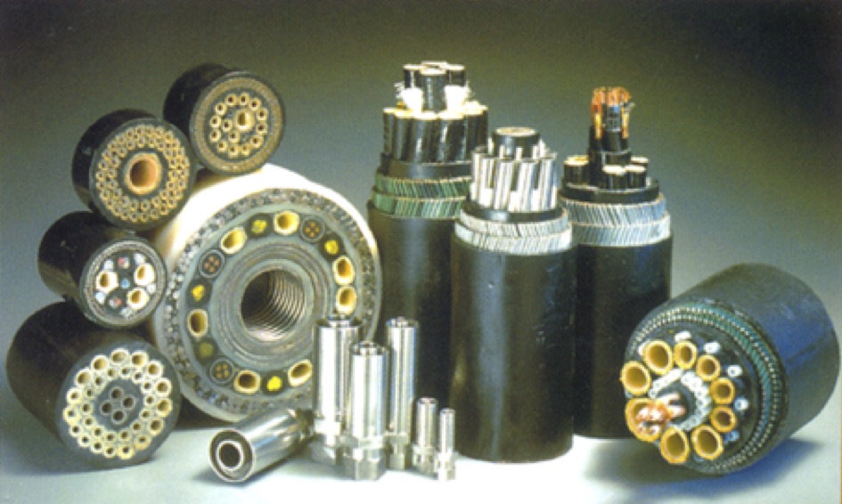
Umbilicals are a combination of thermoplastic hoses, electrical cables, fibre optics and/or steel tubes which are assembled together to form a circular cross section. In order to provide axial tensile strength and abrasion resistance, the product can be supplied armoured with steel wires prior to extruding an outer thermoplastic sheath or applying a roving layer. Different types of umbilical are shown in Figure 3.1, “Sample of different umbilical types”.
The increasing use of subsea production systems for the exploitation of oil and gas has resulted in increased complexity of such systems. Additionally, as the confidence has been developed in the use of subsea systems, there have been considerable increases in the offset distance from the ‘Host’ platform. This has resulted in a very significant increase in the quantity of hydraulic lines being employed in many subsea developments and it is not uncommon to find a single development employing over 300 km of hydraulic lines. Coupled with the ever-increasing number and complexity of control and well service fluids it is important that compatibility between the hydraulic lines and these chemical fluids (i.e. material selection) is carefully addressed if service problems are to be avoided. The same considerations need to be given to all materials of construction used to contain service fluids within the overall system, e.g. seals, rigid pipe assemblies, etc.
The design of an umbilical mainly features:
Fulfilment of all the required functions;
Material selection based on (1) fulfilment of their function, (2) compatibility with the other materials and fluids to be transported;
Internal and external pressure, installation (compression and tension) loads, thermal and dynamic loads shall be taken into account;
Fatigue life must correspond to the required operating life;
Internal and external corrosion must be addressed;
Stability on seabed;
Optimisation of the umbilical section to achieve the best dynamic behaviour, and eventually to obtain similar dynamic characteristics to adjacent risers (if possible).
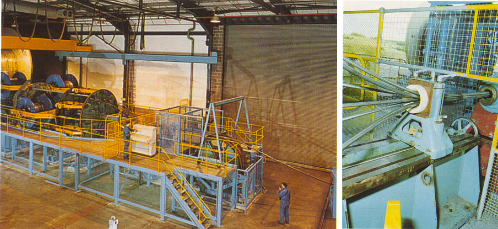
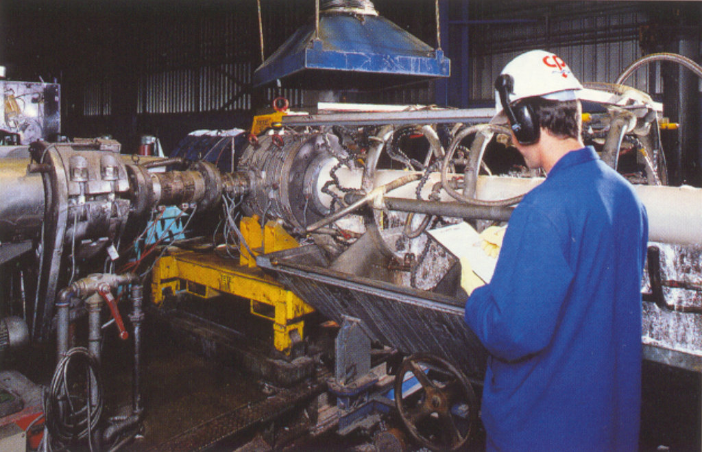
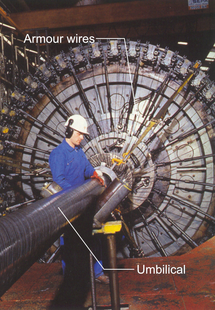
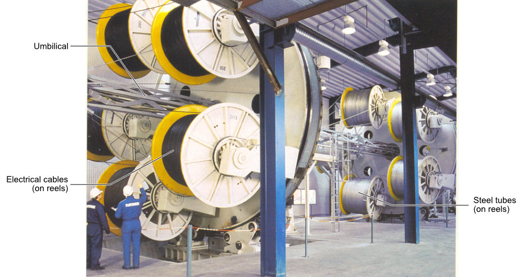
The manufacturing techniques used in the production of umbilical are similar to those used for un-bonded flexible pipes Ref.[20]; essentially helical lay-up, extrusion and armouring as shown in Figure 3.2, “Helical lay-up machine for steel tube umbilical” to Figure 3.5, “Helical lay-up machine for Integrated Service Umbilical (Aker Solutions)”:
However, several manufacturing processes are unique to the production of umbilical:
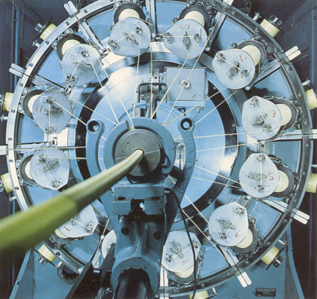
Thermoplastic hose braiding reinforcement. In order to reinforce a thermoplastic hose liner to provide a specific working pressure, large capacity high-speed braiders are necessary to apply high strength Aramid fibre (see Figure 3.6, “Hose braiding machine”). Unit lengths varying from a few metres to more than 20km can be manufactured without joint
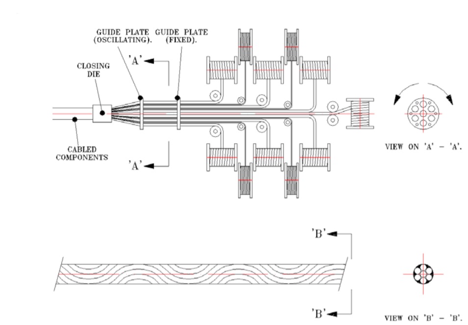
Umbilical assembly line. The functional components can be assembled using the reverse helix technique (i.e. clockwise and anti-clockwise alternated layers, method known as SZ) which provides the umbilical with the required flexibility. The SZ assembling machine is also used for the manufacture of integrated service umbilical and gas lift umbilical.
The main manufacturers of umbilical are:
TECHNIPFMC
NEXANS
AKER SOLUTIONS
OCEANEERING
PRYSMIAN
NKT
JDR CABLE SYSTEMS
Full details (address) are provided in enclosed Appendix A, Manufacturer lists.
The following sections present the technology and manufacturing process used in the production of different types of umbilical implemented in Deepwater applications, i.e. power & control umbilical, thermoplastic hose umbilical and steel tube umbilical (including integrated service umbilical).
3.2 Functions and Dedicated Lines
The electrical lines are divided into two categories:
Power cables for the power supply of offshore platforms and subsea production equipment (control pod, repeater, pilot control valve, electric pumps, etc.);
Signal cables for the remote control/monitoring of subsea production equipment (operation of pilot control valve, read-back of wellhead status and operating parameters, etc.) from host facilities (fixed platform or floating production system).
The hydraulic lines (thermoplastic or steel tubes) can be employed for a variety of duties, typically:
Hydraulic (high or low) Power (operation of actuators);
Signal (operation of pilot control valves);
Data (pressure monitoring);
Fluid transmission and chemical injection (well service and platform utilities).
Hydraulic lines may be either reinforced thermoplastic tubing or steel tubing. The former can be in very long continuous and seamless lengths, whereas the latter are produced from shorter lengths, which are butt-welded to achieve the final production length. The shorter lengths may additionally be seam welded as part of the steel tube production process. NDT and heat treatment shall be carefully supervised as possible source of failure.
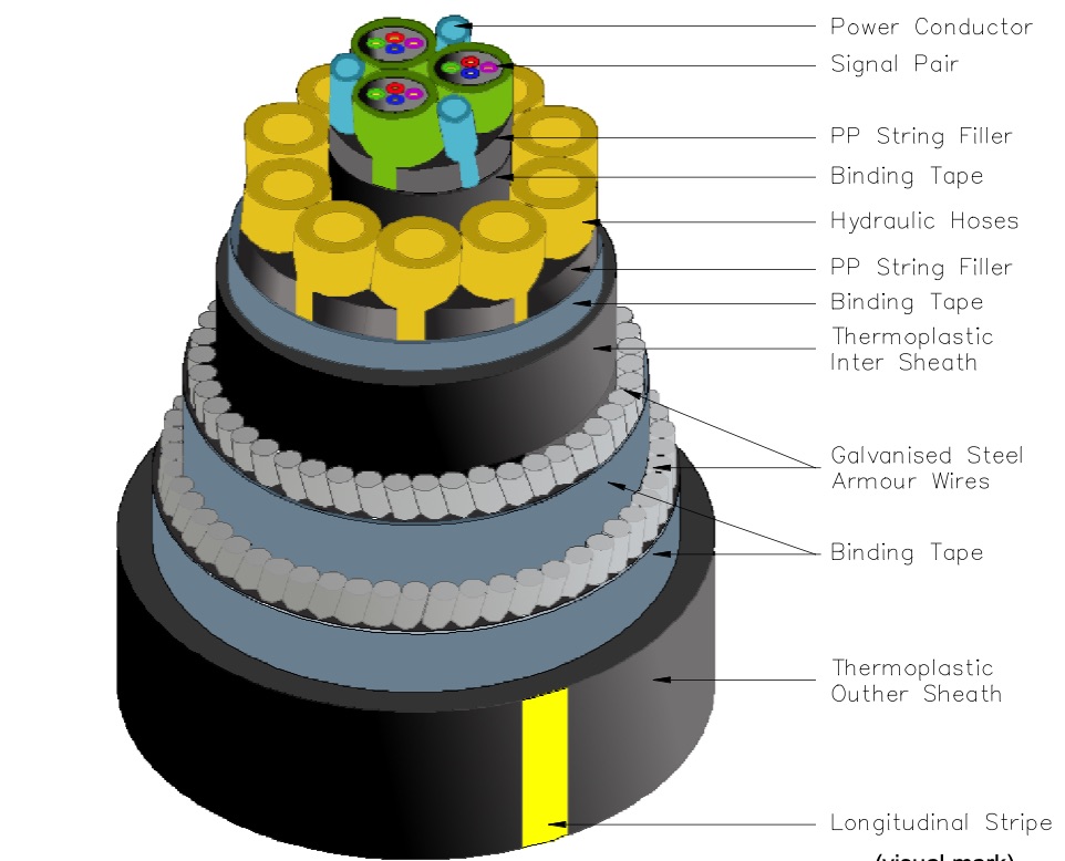
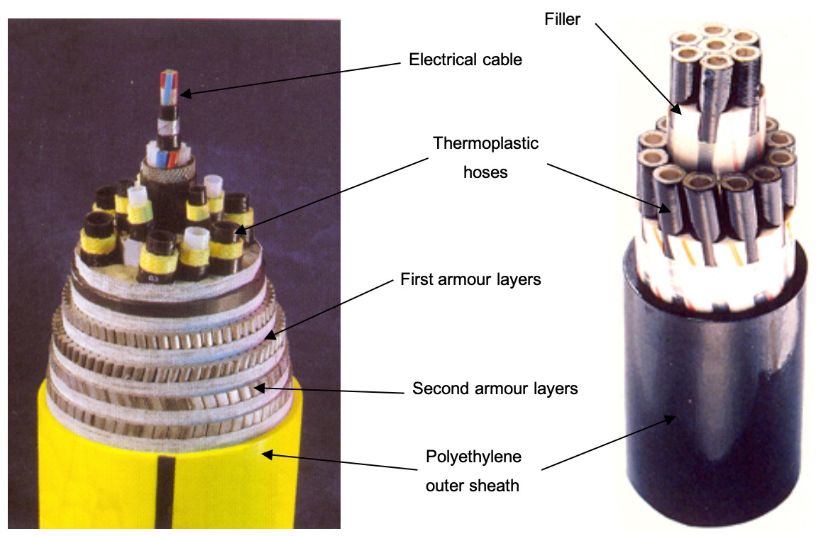
The arrangement of hydraulic lines and electrical cables in a typical umbilical is shown in the following Figure 3.8, “Typical structure of electro-hydraulic umbilical”:
3.3 Power and control umbilical
3.3.1 General
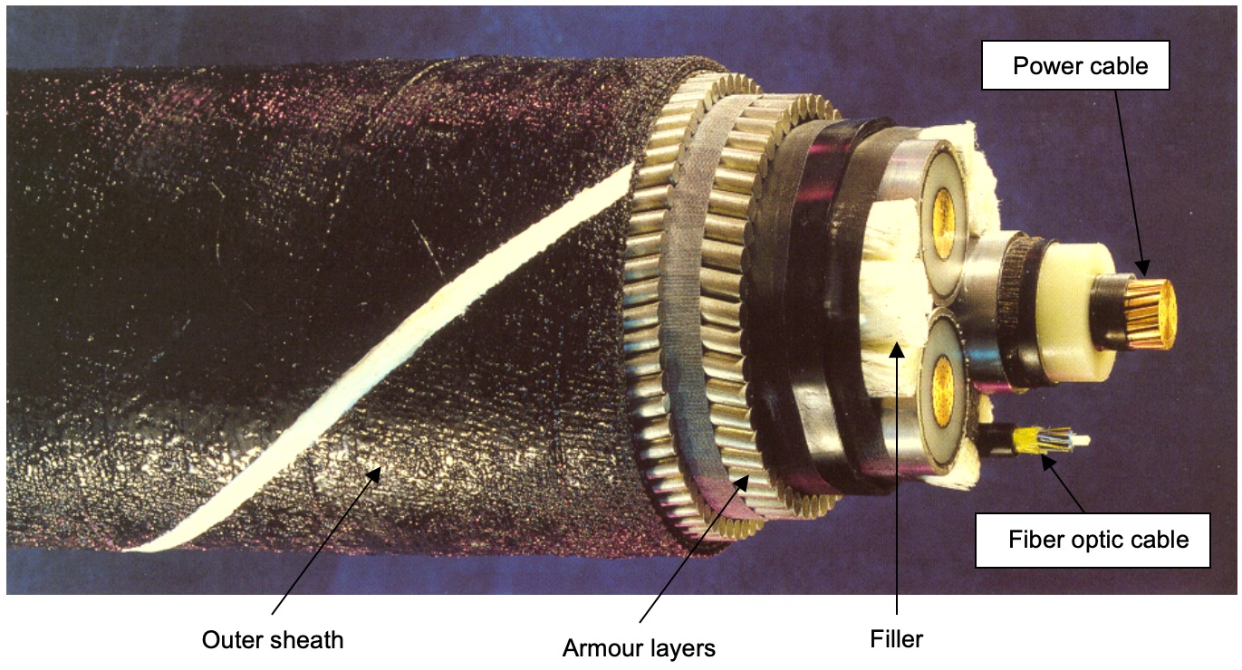
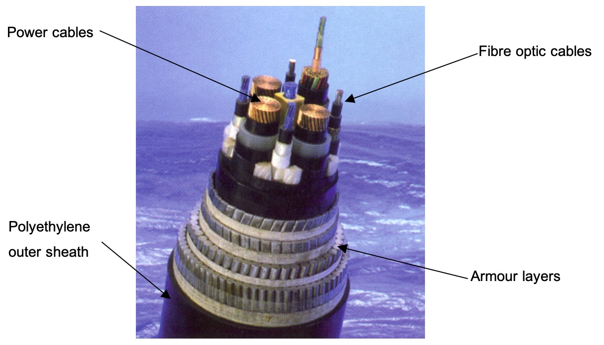
The supply of electrical power from shore to platforms, between platforms or from platform to subsea production/compression system is performed by means of submarine power cables (see ). Supplying power to offshore installations from energy sources onshore makes for smaller and lighter offshore structures, lower manning requirements, and lower CO2 emission levels. With this solution any number of installations can be linked and provided with power from a common onshore power source. The power supply cable system can be expanded to form a network between offshore fields, providing flexible and safe power utilisation for the oil and gas industry. Two types of submarine power cables are to be distinguished “dry” design or “wet” design the former being more reliable but at higher cost.
The remote control of unmanned installations is another application for submarine composite cables. Most subsea power cables installed offshore have a fibre-optic element containing 8-32 optical fibres for signal transmission. The advantages of combining signal and power capabilities in one cable are:
communication will not be influenced by weather or surface traffic;
greater bandwidth compared to radio frequencies;
higher data transmission rate with optical fibres.
Advanced umbilical for the transmission of power, signals and fluids have been produced for the management and control of subsea wells. Electrical power and signal cables are designed and manufactured to suit the final bundle make-up, each component being sized to ensure a balanced and circular construction. Insulation and sheath materials are carefully selected to meet the requirements of the application.
For subsea applications insulation materials are usually thermoplastic compounds, including polyethylene, cross-linked polyethylene (XLPE), polypropylene, polyurethane and PVC.
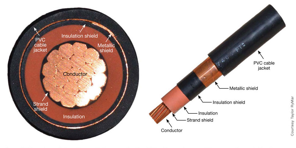
Electrical conductors comprise multi-strand copper, either tinned or plain. Strand size is determined according to specification (see Section Section 1.2, “Codes, Standards, Specifications and Reference Documents”) and/or duty. Multi-strand construction ensures good flexibility for dynamic duties.
Data and signal transmission line options include twisted pair, triads or quads (screened if required) and coaxes of various specifications, all optimised for particular attenuation, capacitance, cross-talk, resistance and other required electrical parameters. To avoid electro-magnetic interferences, power cables are screened using either copper braid or aluminium/polyester film. Components are screened individually or in appropriate groupings, taking account of heat build-up and storage/handling requirement (i.e. minimum-bending radius).
Fibre optic cables, where required are selected from standard basic units and then further processed as necessary (no limitation considering total length). Fibre optic is being used more widely for data transmission because of their large bandwidth capability and without interference problems. Multi- and single-mode fibres are available in a variety of buffering systems. Loose buffered systems utilise fibres in plastic or steel tubes, while tight buffered systems typically include a steel armour or Aramid reinforcement (see Figure 3.10, “Dynamic power and control umbilical”).
The process of power cable or service umbilical manufacturing is as follows:
Lay up: To achieve the best dynamic performance and to prevent stress build-up in the components during bending, all components are helically laid-up in a full 360 degree cabled construction. This promotes flexibility and helps to prevent transmission of stress to the component during dynamic applications;
Armouring: Lightweight wire, or heavy duty contra-helical wire armour, can be provided for umbilical, where required. Such armouring gives damage-protection from ship's anchors or from rock dumping or provides high tensile strength dependent on design. Armoured cables are torque balanced and can have either a single or double wire armouring to ensure maximum strength and protection according to application;
Strength members: Aramid fibre braided strength members may be applied to provide high tensile strength, flexibility and low weight. Alternatively, central wire rope strength members can be used, if required;
Sheathing: Extruded sheathing of most thermoplastic materials (polyurethane, polyethylene, nylon 11, polyester elastomer, polypropylene impregnated with bitumen are commonly used) is available for maximum mechanical protection and service life. Materials are selected for their resistance to a seawater environment, durability under handling and cost.
3.3.2 High voltage direct current power cable:
For application where a long distance is to be covered, high voltage direct current umbilical can be used. For instance the “Rio Madeira HVDC system” enables the power transport of 6300 MW with a direct current voltage of 600 kV along 2375 km. The choice of direct current, and thus the need for a converter station at both extremities, instead of alternating current was made in order to limit the energy losses along this long-distance connection.
3.3.3 Power cable for subsea pumps application
The use of subsea processing (e.g. phases separation) and pumps as regard to flow assurance and artificial lift issues (Ref.[34]) becomes an important application for power cables.
Ranges of power carried by subsea umbilical are presented through the following examples:
For Jubarte field pilot project (Petrobras project, offshore Brazil), an electrical subsea pump of 900 HP (671 kW) was used for artificial lift purpose. The required power was provided by a special umbilical integrated with power cable from FPSO P-34 to X-tree. Beyond its conventionnal functions as hydraulic control, chemical injection and electric signal carrier, the structure comprises the electrical supply cable;
The world’s longest subsea umbilical was laid in August 2006 connecting the Snohvit field in the Norwegian Barents Sea to onshore control terminal. Featuring a single length of 144km, the umbilical manufactured by Nexans sets a new record for remote operation of subsea gas well. The 95mm diameter umbilical contains two three phase power cables capable of delivering 6kW at 3kV, two fibre optic cables, three 1” diameter hydraulic fluid lines and a ½” diameter chemical injection line;
To provide control and power to a subsea (gas) compression station, a 420 kV XLPE cable has been installed at the Ormen Lange field (Norway, December 2006). This is one of many innovative submarine cable installations that Nexans Norway's Halden facility has pioneered over the years. An extensive test programme was established at the tender stage to qualify the 420 kV XLPE cable system for this project. This included mechanical and electrical testing according to appropriate standards. Tests were also performed to verify the fatigue life of the lead sheath for a design life of 40 years;
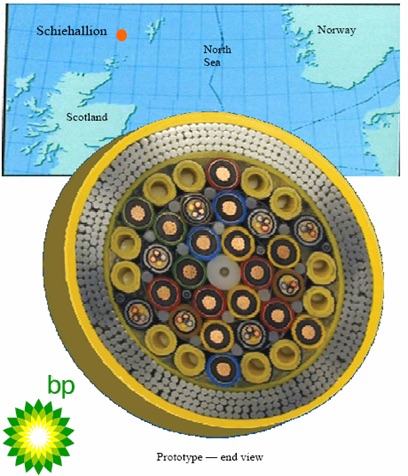
The world’s largest and heaviest subsea umbilical was recently fabricated by TECHNIPFMC for West Shetland project (see enclosed umbilical cross section). This umbilical has a weight of 187kg.m-1, a diameter of 300mm and length of 3900m. This umbilical is dedicated to provide power (4 off 3-phase 15 kV screened cables) to 2x2 multi-phase subsea pumps (2MW) in 350m water depth. The main electrical components are 16 off 95mm² screened 15kV cores and 8 off 10mm² quad low voltage cables.
The medium voltage (MV) power cable in the 4kV – 30kV range when exposes to the ‘host’ floater dynamic motions will experience high fatigue loads within the power conductor made of copper (C101).
To further improve the power cable reliability and performance; the current main topics for R&D are as follows:
Use of copper beryllium alloy (CuBe 3AT) as conductor cable will improve the fatigue life by 15 times over copper conductor;
Use of aluminium alloy (AA8030) conductor cable will improve the fatigue life by 10 times over copper conductor. Use of aluminium alloy has two additional benefits: umbilical weight saving (1/3 lighter than copper) and cost saving (lower material cost than copper);
Use of XLPE as cable insulation (cross linked polyethylene).
3.4 Thermoplastic hose umbilical
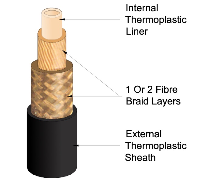
The construction of a typical thermoplastic hose comprises a seamless thermoplastic extruded liner, reinforced by one or more layers of braided high strength textile yarn, and an outer thermoplastic extruded sheath for mechanical protection (see Figure 3.13, “Typical flexible hose structure”). The liner (sometimes referred to as core tube) acts as a seal between the fluid and the external layers and is the means of containing the transmitted fluids. To achieve the design life for the umbilical system, it is imperative that a high level of compatibility exists between the liner and the contained fluids.
Thermoplastic hose liners are produced using an extrusion process. Polymer, in granular form, is melted and forced through a pin and die arrangement to produce a tube, initially greater in diameter than the finished product. Whilst still molten, the tube is drawn through a sizing die to reduce it to the required size, immediately followed by rapid cooling to solidify the product, to facilitate passage through the hauler and spooling onto the storage reel.
In the extrusion process, forcing material through the breaker plate and die arrangement, can result in the liner tube exhibiting anisotropic properties (e.g. out of roundness hose).
To allow the hose liner to transmit fluid at high pressures, the liner tube is reinforced with braided textile yarn. When pressurised, the hose liner is forced against the braided material resulting in some material flow into the interstices of the braided arrangement. This can result in varying stress levels around the circumference and along the length of the liner.
Some thermoplastic hose umbilical are shown in the following Figure 3.14, “Dynamic electro-hydraulic (left) and Static hydraulic (right) thermoplastic umbilicals”.
Figure 3.14 - Dynamic electro-hydraulic (left) and Static hydraulic (right) thermoplastic umbilicals
The fibre braids typically of high strength Aramid fibre provides the mechanical strength to resist to the hoses internal pressure.
Standard end couplings can be attached to the hose in the normal manner, i.e. by one of several swaging techniques.
In the early days of subsea production, Polyamide 11 (PA11) was the commonly employed material construction for the hose liner and there were relatively few fluids to be conveyed. These were typically water based controlled fluids and methanol. With the introduction of electro-hydraulic control systems demanding high levels of system cleanliness and thus ultra clean hydraulic lines, an alternative, Thermoplastic Polyester (with lower permeation rate), was employed to satisfy this aspect.
The hoses used have to transport many different chemical fluids and also transmit hydraulic power. The problem with chemical fluids (e.g. methanol, glycol) used for hydrate formation prevention, is that it permeates through the current industry standard hose lining materials.
This permeated fluid, which is retained by the umbilical inner or outer thermoplastic sheath, due to the thicker section and different material used, builds up within the umbilical structure and egresses from the umbilical at its ends. With fluids, such as methanol, disposal of significant quantities can present problems (environmental, cost).
The introduction of XLPE (cross linked polyethylene) hose lining material has greatly reduced permeation rate, almost zero at seabed temperature, and is also resistant to a wide range of commonly used injection and hydraulic fluids.
XLPE proprietary lining material was developed using a specific grade of HDPE, which is cross-linked using an original and patented (TECHNIPFMC), cross linking process.
The action of cross-linking HDPE slightly improves its mechanical characteristics, but moreover it drastically improves its blistering resistance and its chemical resistance to liquid or gaseous hydrocarbons.
The trend towards Deepwater also led to the development of high collapse resistance hose (HCR), which includes a spiral flexible metal former under the core tube. The flexible inner core is designed to withstand the external seawater pressure and to prevent the hose core from collapsing. The HCR hose requires a different type of coupling which has a welded construction. The metal former inside the coupler slides inside the spiral hose support and seals by swaging onto the outside of thermo-plastic liner.
3.5 Steel tube umbilical
Umbilical in general are vital parts of the underwater production technology. But their reliability has been questioned, as many problems have occurred during laying and operation. Therefore improvements have to be performed in order to increase the reliability of the product. It is also relevant to compare the umbilical reliability with the subsea communication (trans-ocean) cable reliability. The latter product group has a remarkable good track record, and "mature" umbilical designs should be expected to have the same kind of reliability.
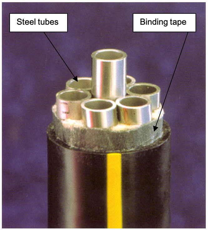
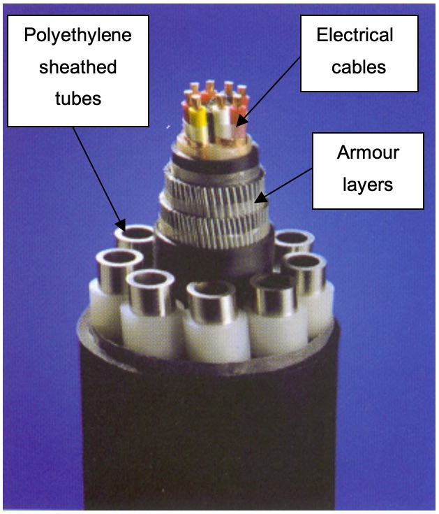
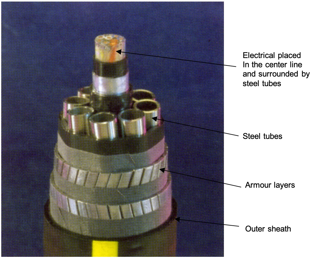
One of the problem areas was that the inner liner of the thermoplastic hoses showed compatibility problems with some hydraulic fluids and with methanol in particular. To comply with these compatibility problems the metal tube umbilical was introduced in the early 90’s, first for static applications then for dynamic applications (see Figure 3.16, “Typical hydraulic steel tube umbilical (for both static and dynamic applications)” and Figure 3.17, “Dynamic electro-hydraulic steel tube umbilical”).
Metallic umbilical, in which the traditional kevlar reinforced thermoplastic hoses were replaced by steel tubes, has several advantages over the traditional thermoplastic hose umbilical with respect to permeation, fluid compatibility, hydraulic and mechanical properties (e.g. collapse resistant).
Metal tubes offer potential technical, cost and reliability advantages, especially in deep waters. Different materials could be considered for metal tubes (some of them being part of R&D developments): carbon steel, zinc coated carbon steel (coiled tubing), duplex, super duplex stainless steel, lean duplex, titanium grade 12 or composite material. However, super duplex seamless tube is the preferred material for umbilicals. Most of umbilicals are made with seamless super duplex butt (girth) welded tubes.
Using steel in dynamic applications opens up challenges, which must be overcome. The major challenge with respect to dynamic steel tube umbilical is fatigue, and details of the general arrangement and configuration of the related products can be decisive on whether the required life is met or not.
Super duplex steel tube has up to now been the preferred steel material used in dynamic umbilical due to high corrosion resistance. Coiled tubing made of zinc coated carbon steel has already been used in a number of static umbilical projects. A testing program carried out for Deepstar Phase 3 showed that the fatigue properties of zinc coated carbon steel tube make it suitable also for use in dynamic umbilical applications.
The lean duplex (ferritic-austenitic, Alloy 19D, UNS S32001) is a recently commercialized stainless steel. Compared to conventional duplex and super duplex stainless steels, it features a reduced chromium content, manganese is substituted for most of the nickel, and molybdenum is essentially eliminated. It offers the higher strength associated with duplex stainless steel. It has been used to manufacture umbilicals for several subsea installations in the Gulf of Mexico, with an externally extruded zinc sheath. However, other external protection systems are being considered. The coils of seam welded tubing contained strip splice, longitudinal seam and orbital welds.
In selecting the design parameters for a metal tube umbilical, the following topics must be considered:
Simple cross section formed solely of helically wound metal tubes is a viable and potentially economical design (versus thermoplastic hose);
If included, the electrical conductors require protection from crushing loads (e.g. laying tensioner) and allowing the electrical conductors to move axially may improve the fatigue life and reduce likelihood of damage during installation. This is performed by means of PVC sheath;
Proper selection of materials plays an important role in determining the lowest cost solution. Fluid compatibility and corrosion protection will also influence the selection;
Design details, such as splices, spooling, terminations and installation procedures, are important in successfully placing an umbilical into service without defects or damages;
Armouring and other layers that are candidates for incorporation in the umbilical cross section should each be considered carefully on their merits, that is, whether they actually increase reliability or serve a vital function.
The requirements for well service and length of the umbilical usually determine the number and internal diameters of tubes, and if included the size and number of electrical conductors.
In making choices about the umbilical configuration, the designer must be aware and take into account all the facets of the umbilical application. This includes manufacturing process and equipment available for manufacture, installation method and procedure, static and dynamic loading, mechanical handling, storage, stability on seafloor, termination at the well and platform, cathodic protection testing, internal cleanliness, and repair. All of these aspects may be important in the installation and successful operation of an umbilical.
Typical manufacturing process of metallic umbilical is as follows:
Seamless tube joints (in approximately 20m lengths) are welded together and put on small reels to bring the length up to required length. Butt welds in the tubes are carried out using orbital welding techniques (e.g. Gas Tungsten Arc Welding system) on a dedicated welding line, and are then passed through a real time radiography unit for validation. Radiographic results are stored electronically. This system enables rapid retrieval if historical examination should be required;
These reels are then loaded directly onto a vertical lay-up machine, and the tubes are helically bundled, tape-wrapped, and placed temporarily on a turntable storage carousel with diameters of 22 to 26 meters and weight capacity of about 600 Te approximately;
From this carousel, the umbilical is passed through an armoured machine or a polyethylene / polyurethane extrusion machine (or both) for armouring and sheathing. The completed umbilical is then taken up and stored by reel or carousel ready for termination head installation, factory acceptance test and dispatch.
Conventional steel tube umbilical is composed of a static umbilical laid on the seabed and a dynamic umbilical suspended to the fixed or floating production system. Some samples are shown in the Figure 3.18, “Dynamic and static electro- hydraulic steel tube umbilical”.
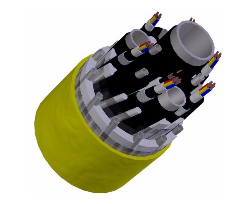
3.6 Integrated service umbilical
The typical integrated service umbilical is a combination of one or more of the hereunder listed elements:
Service lines;
Hydraulic lines;
Chemical lines;
Fibre-optic cores for data transmission;
Electrical cables for power supply;
Electrical cables for signal transmission.
The cross-section structure of the umbilical is designed to handle the various characteristics of the individual elements. The concept offers full control of mechanical stresses and strains, combined with maximum flexibility.
All elements in the cross-section are bundled together in a continuous helix. The outer sheathing is of extruded polyethylene or polyurethane.
It offers the following main features:
Resistance to aggressive fluids;
Suitability for small and large diameter tubes;
Subject to extremely high pressure over long distances;
Continuous umbilical length for long offsets;
Combination of service/production lines within the same umbilical;
Increased lifetime of the umbilical (due to high tensile strength and stiffness of steel tubes);
Steel tubes can eliminate the need for additional armouring.
The market of integrated service umbilical is dominated by four major manufacturers: TECHNIPFMC, AKER SOLUTIONS, NEXANS and OCEANEERING.
Aker Solutions integrated service umbilical technology differs from general umbilical design philosophies.
In conventional ISU, the elements are kept together by rubber or plastic material, which lock the elements in their position in the cross section (see Figure 3.19, “Conventional integrated service umbilical (ISU)”).
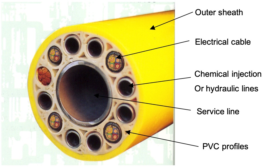
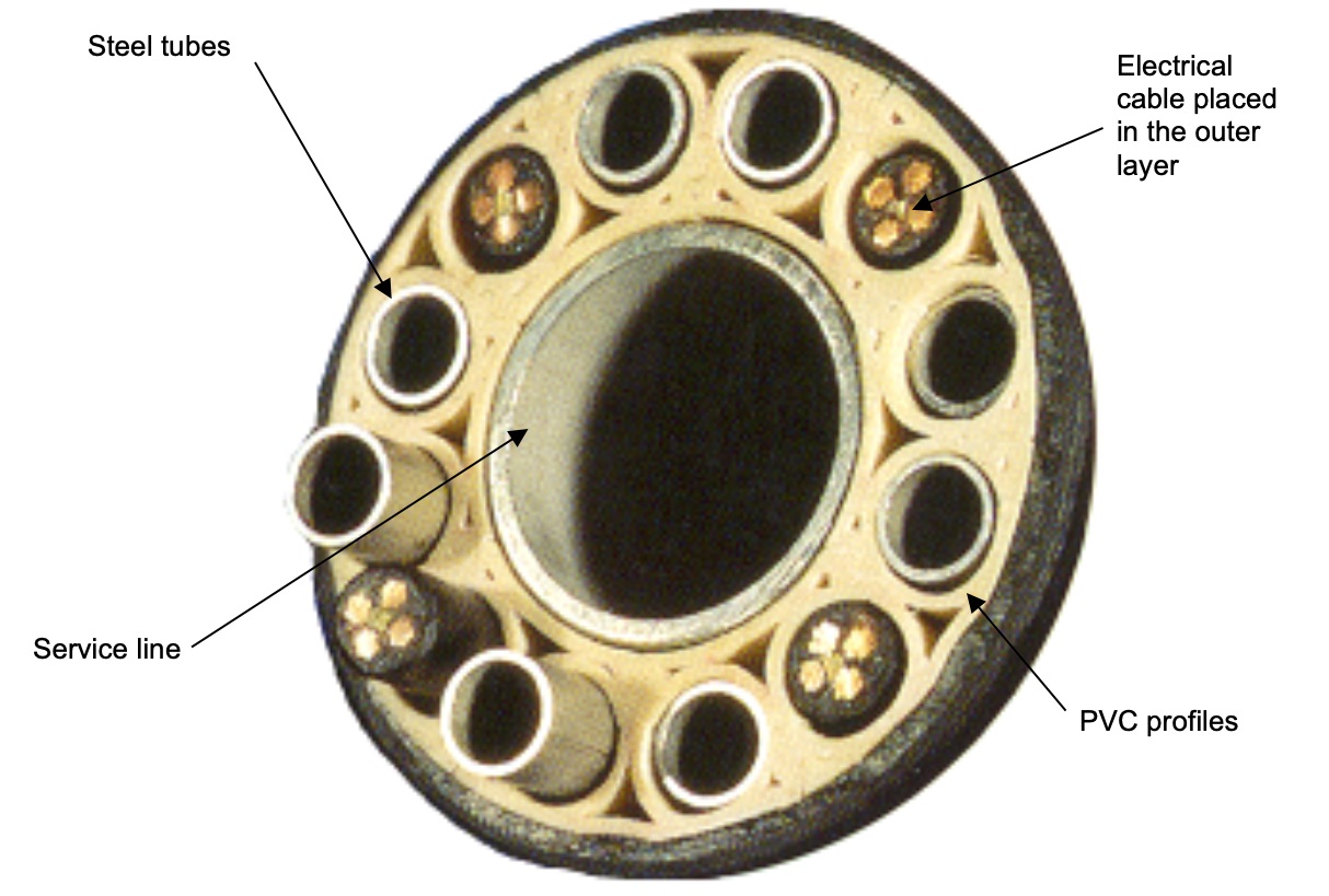
In the Aker Solutions integrated service umbilical, hydraulic lines are combined with electrical cables and/ or fibre optic cables in a composite cross-section, the elements are separated by unique (patented) PVC profiles. These conduit profiles ensure that the cables and steel tubes are free to move relative to other elements and not be exposed to lateral loads as elements are not adjacent (see Figure 3.20, “Aker Solutions integrated service umbilical”). The PVC profiles is acting as a load transfer means between the tensioner external clamping loads onto the central tube axial tension load during the ISU laying operation.
The lay length of the Aker Solutions ISU is relatively long compared to conventional umbilical technology. The Aker Solutions ISU is torque balanced as the manufacturing process ensures a controlled back twist of the hydraulic tubes. Umbilical loops during installation have never been experienced for any Aker Solutions umbilical (e.g. Norsk Hydro TROLL, NJORD, VISUND).
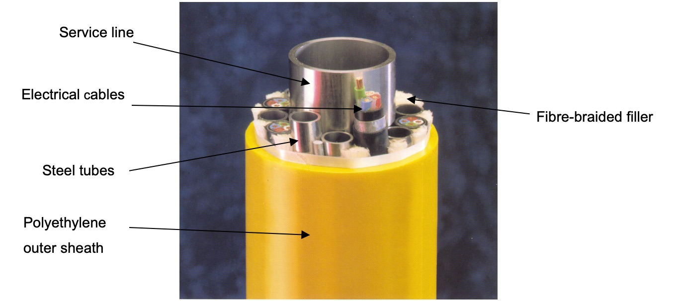
The integrated umbilical concept allows individual design to suit a range of applications capable of transferring hydraulic fluids, electrical signals, power and fibre-optic signals. Service lines (typically 1,5" – 4") can be included and are placed in the centre, with the electrical signal and power cables, fibre optic cores and hydraulic tubing placed circumferentially around. The circumferentially placed members follow a helix trajectory. Each element is designed to sustain hydrostatic pressure.
The axial strength in the integrated umbilical design is provided mainly by the central metal tubing. Separate armouring layers to sustain axial loads and stresses are therefore not necessary.
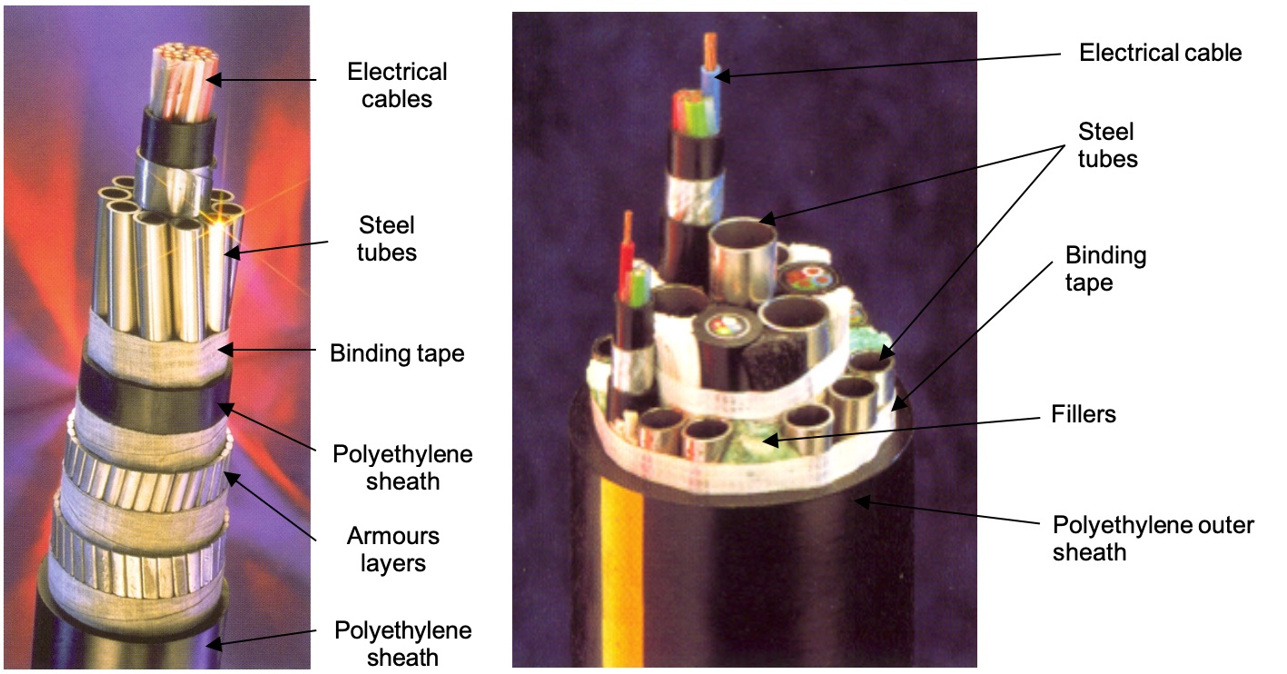
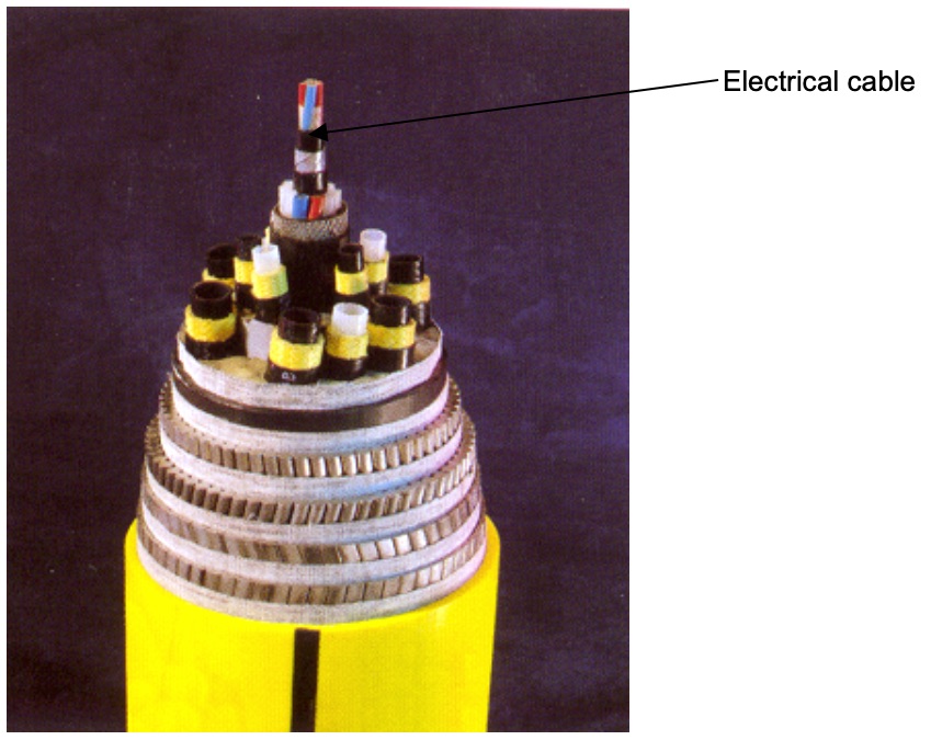
In classical thermoplastic or steel tube umbilical the electrical cables were placed in the centre of the section (see Figure 3.21, “Electrical cables position in a thermoplastic umbilical” and Figure 3.22, “Electrical cables position in a typical steel tube position”), Electric and fibre optic elements can be placed in any position within an integrated service umbilical (see Figure 3.23, “Electrical cables position in a integrated service umbilical”).
TECHNIPFMC proposes also an integrated multi-service umbilical with one 2’’ methanol line in its centre. ¾” hydraulic and chemical lines and power cables are located around the 2” tube. This design was used for TOTAL DALIA field production umbilical (Figure 3.24, “Cross section of DALIA production umbilical (TECHNIPFMC design)”)
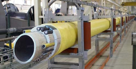
The manufacturing of integrated service umbilical is based on either an horizontal (Aker Solutions technology) or vertical (TECHNIPFMC technology) axis machine capable to support fifteen bobbins, each of which is capable of holding fifteen metric tons of tubing or electric cable.
These unique manufacturing capabilities allow the production of integrated service umbilical with up to six-inch service line in the centre, with the control functions placed around the circumference. If required, the service function can be achieved by design with a large bore centre tube (see Figure 3.24, “Cross section of DALIA production umbilical (TECHNIPFMC design)”), but also with several smaller tubes (e.g. 10 x 1'' on Rosa dynamic umbilical). The steel tube umbilical is designed for virtually any service application. Operating conditions will determine if the tubing material will be carbon steel, zinc coated carbon steel (coiled tubing), 316L duplex or super duplex stainless steel or titanium grade 12.
The manufacturing process of Integrated Service Umbilical is as follows:
Seamless tubes in length up to 23m are butt welded and progressively spooled into reels. The length of any reeled tubing depends on the tube size. The tube string welding is run on line composed of programmable orbital TIG (Tungsten Inert Gas) welding stations, real time X-ray inspection and CD recording. The Non Destructive Examination (NDE) system of inspection provides a 100% traceability ensuring that individual tubes and welds throughout the production are identifiable to their location within the completed umbilical and mapped to achieve a complete manufacturing history traceable to the original material certification;
Completed tube strings are hydrostatically pressure tested prior to release for the umbilical lay up;
Tested tube strings are loaded into the umbilical lay up machine;
Seamless central service line are welded together and stored on the carousel. Welding, NDE and pressure test are performed as for the above seamless tubes;
The hydraulic/chemical tubing strings and electrical cables together with the PVC profilers are helically laid up around the central service line;
The circular bundle is 100% tape wrapped then directed to a temporary storage carousel. During the lay up operation tube to tube weld joints and electrical splices are performed in order to produce the required length;
The umbilical is then passed through an extrusion line for the application of the polyethylene outer sheath and routed to a large storage turntable, ready for factory acceptance test, loading and transportation to the offshore site.
3.7 Integrated Production Umbilical
The IPU concept (developed by Aker Solutions) allows any operator to incorporate a central gas lift or production flowline in the size range between 2” ID and 10” ID within an overall umbilical bundle like design.
The IPU is designed to combine the normal function of an umbilical with a production or an injection line, and also for supplying high voltage power (between 6 and 12 kV).
Suitable flow assurance in the flowline is achieved through a combination of thermal insulation and active heating.
IPU can be used in static or dynamic application. At report date there is no field/track record and only test samples IPU have been produced (Figure 3-24).
3.7.1 IPU cross section
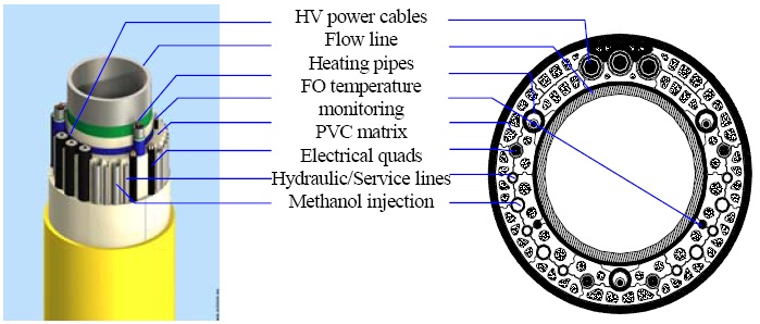
Figure 3.25, “Typical IPU design” presents an exploded view of the IPU main body, which basically consists of the following elements:
A 103/4 “ static flow line with a 3 layer PP coating (4mm thick for static section and 14mm thick for riser part);
Around the flow line, there is an annular shaped PVC matrix that keeps in place the spirally wound umbilical tubes and cables and provides thermal insulation to the flow line;
Embedded in the PVC matrix, but sliding freely within it, the various metallic tubes for heating, hydraulic and service fluids, the electrical/fibre optic cables for signal, and the high voltage cables for power;
An outer protective sheath of polyethylene 12mm thick.
3.8 Umbilical reliability and redundancy of functions
The control umbilicals are the “life lines” between the topside control facilities and the subsea production system. Losing such a line would mean shut down and loss of production.
This is why, despite of high costs, redundancy is always included. In general, a 100% redundancy for control functions (power and signal cables and hydraulic tubes) is achieved, while some spares are added for chemical lines. Some operators choose umbilical which have 100% redundancy for all of its functions (e.g. Norsk Hydro on Ormen Lange, see below). The redundancy can be achieved by two different ways:
The umbilical has in its own structure 100% redundancy for all of its functions (chemical, fibre optic, power and hydraulics). For instance, the umbilical used for Ormen Lange field (operated by Norsk Hydro and manufactured by Nexans) has redundancy for all its functions;
Another solution is to have two different umbilical laid with two different routes. For example, on the Total’s DALIA field (Block 17, offshore Angola), production umbilical have been laid in a looped configuration to be able to communicate with the subsea Manifold control modules via two different routes and thus get umbilical with 100% redundancy.
3.9 Subsea termination interface
![[Tip]](tip.png) | Tip Click these links below for access to 3D resources: |
As part of the umbilical technology, there is a wide range of umbilical termination equipment.
The subsea termination interface provides a standardised interface towards the subsea termination assembly.
The steel or flexible lines are capped and terminated with end fitting, while the electrical cables are prepared for termination and water-blocked using heat shrink adhesive caps, prior to factory termination with electric cable subsea connectors ().
The subsea termination interface comprises the following main elements:
Bend restrictor / bend stiffener radius control;
Attachment to the umbilical and the subsea termination assembly (e.g. flanges, connectors);
Tubing support (e.g. tube separator, clamp, resin).
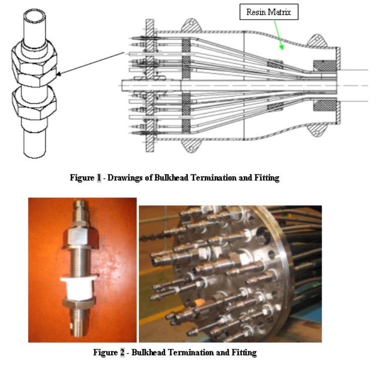
The outer steel tubes (or plastic tubes) are separated from the centre tube by the insertion of a tapered cone over the centre tube and this “sprayed” tube configuration is resin encapsulated within a tubular (casing) compartment. To prevent the tubes from pulling out of the resin, collars are fillets welded or screwed to the tubes (see Figure 3.27, “Subsea termination interface arrangement”) in order to provide a bearing surface against which the resin is poured during assembly. In this way the compressive modulus of the resin rather than the bond strength of the resin to the tube limit the load (or tension) capability.
The loads applied to the umbilical are mainly taken by the interface flange, which recuperates the tension forces through the tube retaining collars and the moments through the bend limiters.
3.10 Subsea bend restrictor
When an umbilical is unsupported over a large free span there exists the possibility of damaging the umbilical structure due to over-bending.
Typical locations at which this problem may occur could be at the subsea connection points and J-tube exits.
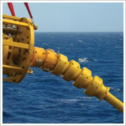
Fitting a device known as bending restrictor prevents over-stressing of the umbilical. A restrictor consists of a number of interlocking half rings, which are fastened together around the umbilical (see Figure 3.28, “Integrated service umbilical equipped with steel bend restrictor” and Figure 3.29, “Bend restrictor schematic” ). The restrictor does not hinder the movement of the pipe until a pre-determined minimum bending radius is reached, at which point the restrictor elements lock.
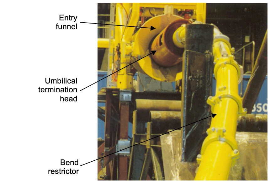
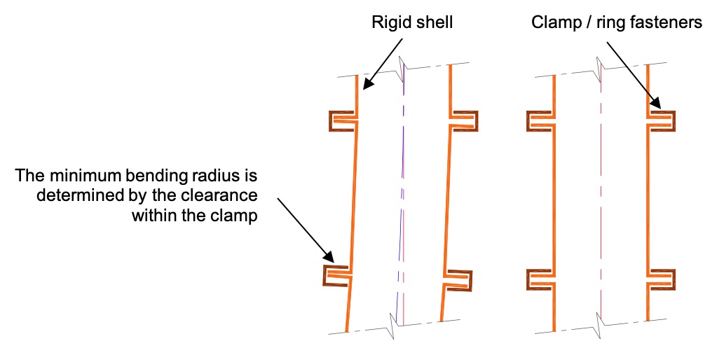
The restrictor and not the umbilical subsequently carry additional external bending loads.
The subsea bend restrictors can be either based on cathodically protected steel elements or conventional moulded elements. In the latter, the bend restrictor elements, or rings, are manufactured from a specific grade of polyurethane elastomer. The material is tough, semi-rigid and creeps resistant.
The steel material is preferable to the plastic elastomer, with respect to preventing over-bending of steel tube umbilical. The steel bend restrictor also provides better definition of mechanical characteristics or improved strength. The subsea steel bend restrictor is purposely designed for each individual application and is provided with cathodic protection.
The restrictor ring fasteners are not connected to a cathodic protection system and so they are supplied in highly corrosion resistant materials.
Bending restrictors could be installed either onshore or (if reeling problems are expected) offshore prior to the laying operation.
3.11 Topside bend stiffener
Dynamic umbilical may be secured to rigid structures such as fixed flanges mounted on top of I/J tube at the hang off platform, with or without emergency release connectors. The presence of environmental loads will subsequently cause the pipe to bend near this hang-off point. With respect to dynamic steel tube umbilical, the greatest challenge to overcome is fatigue. And the most critical area with respect to fatigue is usually this interface area between umbilical and floating production system. The bending in combination with large axial loads may cause damage to the umbilical structure due to overbending.
To prevent structure damage due to overbending the umbilical termination may be supplied with a dynamic bend stiffener, which protects the umbilical from the wave, currents and vessel motion induced bending in the interface area, and ensures the umbilical’s required design life.
The bend stiffener has a single section of graduated profile non reinforced moulded polyurethane elastomer. This material is extremely tough yet flexible and suitable for extended service in a subsea or an above water marine environment.
The topside bend limiter for dynamic steel tube umbilical is a purpose built device. The bend limiter design is based on non-linear finite element calculations and given vessel motions / sea states. The typical parameters needed for the design of bend stiffener are: minimum and maximum axial top tension, maximum top deflection angle, umbilical bending stiffness and minimum bend radius requirement.
3.12 Topside termination system
Riser sections are terminated using a split flange hang off collar. Termination of the mechanical components is achieved by welding the armour wires to a stepped collar, below the hang off point. The topside termination is mechanically terminated in the same manner as the subsea termination (see Figure 3.32, “Topside termination of steel tube termination”).

3.13 External corrosion protection
The armour wire is protected by the galvanisation applied during manufacturing of the wire. Joints, terminations and hardware fabricated in carbon steel and permanently installed subsea, or permanently exposed to the splash zone are protected by zinc plating to BS 1706, Grade Fe Zn 10C/1A, hot dip galvanised or painted to subsea paint specification. Stainless steel are possible for optimum corrosion resistance.
Carbon steel tube external corrosion control includes the traditional use of cathodic protection in conjunction with organic coatings and the use of metallic coatings which could provide both the cathodic protection and barrier coating corrosion control functions.
Traditional cathodic protection techniques include (1) bracelet type anodes spaced at discrete distances along the steel tube elements, (2) large anodes installed on the seabed and connected to the umbilical at longer discrete distances, and (3) continuous ribbon type anode material installed within the umbilical during fabrication. The first two methods would not allow for proper current distribution to the steel tubes through and underneath the umbilical jacket roving. Although the ribbon anode material was designed for this concern, attenuation analyses indicated that the anode material would require an unrealistic number of electrical attachment points.
Metallic coatings have been used for providing corrosion control in seawater immersion in the North Sea, and more recently in the Gulf of Mexico. Thermal sprayed aluminium meets all mechanical and corrosion requirements for steel tube. However, there is a concern around the ability to sustain a high rate of tubing production and economics. An extrusion process would be a more effective method to apply a metallic coating to the tubing with zinc as the coating material. This solution was used for zinc coated wires in complex mooring cables for Tension Leg Platforms. This design uses bitumen type blocking agent.
The barrier coating and cathodic protection functions of a zinc alloy are a function of the alloy’s chemical composition. Zinc alloys typically used for cathodic protection in seawater are quite active and have poor barrier coating properties. Conversely alloys, which exhibit better barrier coating properties, have limited cathodic protection capabilities.
A combination of these properties is required for long term corrosion control of steel umbilical elements. All metallic components of the umbilical are connected to the corrosion protection system at terminations.


