
8 Deepwater Steel Tube Umbilical Design Issues
With the increase of water depth, new concerns appear regarding umbilical design. Some of them are presented in the following sections.
8.1 Axial strength
For a typical Deepwater development, umbilical are hung from the floater in a catenary configuration down to the subsea system on the seafloor. The cross section of a typical control umbilical contains small bore steel tubing to provide strength and support and electrical control cables normally set in or around thermoplastic material such as PVC and PE. Normally, the stiffness from the steel tubes in the cross sections is adequate to prevent the umbilical from over stretching from its own weight. If not, additional steel is usually added to enhance the axial stiffness as well as the dynamic behaviour (increase of weight/diameter ratio for better stability, e.g. under current loads).
While steel reinforced umbilical have been adequate to date with developments reaching water depths up to 2000m, it was found that beyond these water depths, the steel becomes ineffective as a load carrying element and resulted in elongation. This elongation is transferred into a tensile load that, while capable of being sustained by the PVC profiles within the umbilical, was well above the operational capability of the copper electrical conductors and, in effect, shorts out the connection.
As the umbilical elongation is the ratio between the tension in the umbilical and the umbilical axial stiffness, manufacturers determined that adding huge amount of steel was not the way forward to solve the problem.
Some solutions were envisaged:
Use of higher strength materials;
Mid-water buoyancy aiming to take the weight of the umbilical to reduce the strain;
Use of a stepped-diameter umbilical that had a larger diameter near the surface and gradually decreased toward the seabed.
However, higher strength materials have yet to be field proven. Mid-water buoyancy has the drawback to be complex and to lead potentially to clashing. In addition, a stepped-diameter system is difficult to manufacture.
Another solution was developed by Aker Solutions: integration of carbon fibre rods in the cross section. Aker Solutions determined that carbon fibre rods are ideal for stiffness enhancement of control umbilical. The carbon fiber rods have nearly the same stiffness as steel (Young modulus of 150 000 MPa versus 200 000 MPa for steel) but at only 15% of the weight, are naturally buoyant in water and have a low degree of elongation.
By integrating a certain number of these rods in the cross section, the axial stiffness might be enhanced to the necessary level depending on the size and number of rods. These rods enable to eliminate the water depth limitation of today’s traditional umbilical. In addition, this method has an extremely minor impact on cost.
Umbilical with 6.5mm carbon fibre rods interspersed in the cross section have been used in Merganser project.
8.2 Fatigue issues
Fatigue assessment of deep and ultra-Deepwater dynamic umbilical is essential given the critical importance of umbilical systems. Any failure in Deepwater is costly and in the case of umbilical, failure of any one component will often result in well inoperability (by affecting the controls) or reduced flow assurance mitigation measures (by affecting chemical injection) with obvious cost impact. So, it is vitally important to understand umbilical behaviour fully and be able to assess fatigue as accurately as possible.
Improving fatigue analysis of steel umbilical can provide the following benefits:
Reductions in estimated fatigue damage, leading to:
Ability to design umbilical capable of operating under more onerous conditions, in particular deep water applications;
Cost savings on associated hardware, in particular bend stiffeners.
More accurate representation of the actual umbilical service conditions;
Optimization of umbilical structure.
Comparing to traditional approaches, two advances led to more accurate analysis:
Irregular waves modelling:
Time domain analysis softwares (e.g. Orcaflex, Flexcom or Deepline) with appropriate post-processing are used to perform fatigue analysis. Traditionally regular waves model were used as post-processing is easier, but regular waves fatigue analysis are very conservative. Thus, current trend is to use irregular wave modelling to reduce conservatism with appropriate post-processing.
Interaction of all components:
Traditionally dynamic analysis software models umbilical as one homogeneous structure. For risers and mooring systems these tools allow numerical realistic modelling of global line configurations. However, the fact that umbilical consists of numerous helically-wound cables and tubes produces 3D behaviour as a helical structure which these conventional modelling and analysis tools are not capturing.
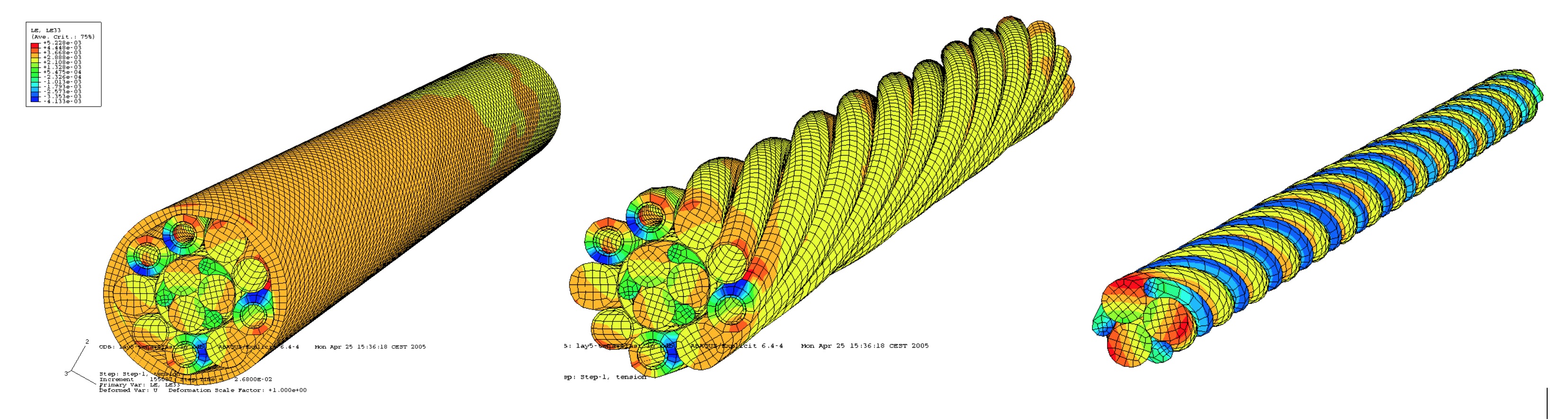
New approach is to consider stress in each component in helical structure and to take into account internal friction and sliding of one component with others. FEA software (Figure 8.1, “Steel tubes ISU finite elements models and analysis (TECHNIPFMC)”) can be used to assess and to provide friction forces between the various components.
Based on the above findings, some umbilical designers developed new methodology to analyse steel tube umbilical fatigue. The methodology steps are presented as follows:
Determination of the mechanical characteristics of the umbilical (diameter, linear weight, axial and bending stiffness, etc.). These values are regularly updated in the iterative design process;
Time domain analysis software simulates dynamic in-place behaviour of umbilical, taking into account irregular waves modelling;
At each time increment, tension and curvatures are logged at critical points;
Post-processing software (e.g. visual basic routine) assess stress sustained by umbilical at critical point at each time increment, taking into account:
Tension at point at the time increment;
Curvatures and bending stress at point at the time increment;
Internal pressure;
Friction contact loads.
Rainflow counting algorithm enables to assess stress bins (stress ranges and associated occurrence);
Miner’s rules are used for fatigue damage summation;
S-N curves and Miner’s summation rules provide the total damage.
TECHNIPFMC developed this type of analysis methodology to assess fatigue behaviour of umbilical. This analysis was used and accepted by Exxon for Mondo project (KIZOMBA C field, offshore Angola) and Total for Dalia.
To conclude on fatigue issues, experience feedback shows that fatigue sources are mainly due to 1st wave and 2nd waves induced motions and not to VIV. The large amount of friction between components results in high internal damping and good energy dissipation. It shall also be noted that the increase of tension (due to increasing water depth and addition of steel rods for a better dynamic behaviour) induces increased friction reactions between components, which has a bad impact on the overall fatigue life.
8.3 Installation
Ultra deep water application demands an umbilical design resistant to high radial compressive loads, as the umbilical will have to resist to the high crushing load induced by tensioner and/or by the laying devices. The umbilical construction shall prevent any damage to inner components during the installation phase, which is the most critical.
Another installation constraint may be the size of the chute required for installation in ultra deep water. The installation chute radius must be designed to limit the contact pressure between the umbilical and the chute to limit the strain in the tubes. The chute radius is dependent on the installation load and the allowable crushing load of the umbilical. The crushing resistance of an umbilical being limited and the installation tension being proportional to the water depth it is therefore obvious that ultra deep water installation require very large chute radius.
The installation load is based on the weight of the calculated length of catenary between the vessel and the seabed plus the weight of the umbilical from the sea level to vessel deck. New installation techniques have to be developed to enable heavy steel tube umbilical to be installed in ultra deep water. Depending on the installation vessel capacity in term of total available contact length of tensioner the current limit is typically 2000m Water Depth for an umbilical with an underwater weight of 30kg.m-1.
Current installation techniques are approaching the limitations on achievable installation depths, due to the relatively low crushing resistance of umbilical structure (e.g. 80t/m). To improve this limitation new predictive modelling of the radial stiffness of umbilical bundles and practical methods of increasing radial stiffness are being developed. This will permit higher values of clamping pressure within the tensioner, and therefore allow installing umbilical in deeper water.
As discussed in Chapter 5, Installation Techniques, when the required tensioner contact length is higher than 10m – 12m, e.g. 3-4 ‘in-line’ tensioners (positioned in series, Figure 2.11, “Umbilical laying equipment for ISU” and Figure 5.3, “Umbilical laying spread general arrangement”) there is a clear advantage to lay the umbilical directly from the storage reel, which must be rated for the lay tensions. In this case the umbilical compression load would be distributed over a longer curve/length (minimum being the reel hub circumference).


