
20 Subsea Transducers/Sensors
20.1 Introduction
Various Transmitters and Transducers are installed subsea to provide measurement of pressure and temperature of the process fluid and gas.
20.2 General
Subsea sensors are specialised versions of surface-located devices and must evidently be constructed to withstand the ambient pressure underwater. This results in particular aspects of the sensors design, construction and interface as outlined in this section. Certain aspects of their operation which personnel are familiar with for topsides operation are not available for subsea devices, which means that their application and mode of operation require particular attention during the design phase.
20.3 Construction
All subsea sensors have to be constructed from corrosion resistant materials - Stainless Steel 316L or Duplex being typically used, particularly for the interface flange. The devices need to conform to relevant standards, such as API performance requirements and should be suitable for the specified class of service.
The devices will typically be constructed using electron-beam and T.I.G weld construction to ensure maintenance-free operation, all welds being helium leak tested during manufacture.
Parts of the unit in contact with process fluids should be constructed of materials to match the conditions, such as Inconel 625. It is usual for at least double-barriers to exist between the process fluid and the environment; this can be achieved in the construction of the device itself, with secondary containment chambers being provided to withstand full process pressure in the event of rupture of the measuring element. SI 289 defines requirements for equipment installed on subsea manifolds and 'tertiary' pressure containment systems are incorporated.
Interface flanges need to be standard designs, such as API 2 1/16" - 10,000 psi type 6BX (API Spec 6A) and can be forged from Super Duplex stainless steel with the BX152 ring groove.
20.4 Interface with display/monitoring system
20.4.1 SCM
All subsea sensors must be powered from, and relay their information to the Subsea Control Module.
The SCM provides a source of power for the sensors, typically 12 or 24 volts for a 4-20mA interface and reads the signal from the sensor, digitises it via an analogue-to-digital converter, then relays it to the surface via the telemetry system, usually in response to a request from the MCS for data from that sensor.
Many SCM designs have the ability to switch off any particular sensor circuit i.e. putting the sensor “out of service” This safeguards the rest of the system in case of a faulty sensor or damaged interface cable, which might otherwise short-circuit the supply voltage. The drive electronics therefore also has to be protected against short circuits, and individual supplies are preferable, so that the other sensors are not affected if one fails.
It is not usual to use this facility to switch off a sensor between readings. Whilst most modern sensors have little or no warm-up time, they may still require 1-2 seconds to stabilise and if the SCM had to wait for this period when reading each sensor, the overall system scan time would be slowed down.
Furthermore, repeatedly switching an electronic component on and off reduces its reliability. A formal reliability analysis does not consider this. An SCM typically reads all subsea sensors as fast as the telemetry system allows, nominally every 2-3 minutes, and so there is little to be gained by de-powering the sensors.
Similarly, the circuitry also should provide for clearing any digital readback value in case of failure of the sensor. If this is not provided locally within the SCM itself, then the MCS will usually change the displayed colour of a sensor reading to indicate fault, as well as displaying any detected under or over range alarm.
20.4.2 4-20mA system
20.4.2.1 Principle
Most subsea sensors operate using a standard two-wire 4-20mA interface.
That is, the equipment to which they are connected supplies an operating voltage, typically between 12 – 24 volts, and the resulting current varies between 4 and 20mA according to the value of the parameter being measured.
Using a current instead of a voltage overcomes the effect of the impedance of the intervening wiring, as the current remains the same whatever the impedance. It also improves the ability of the system to withstand electrical noise. Spurious signals are superimposed on the signal being measured by varying magnetic fields (such as by AC power cables) which induce currents in the conductors. If the conductors are small and close together, these fields generate equal and opposite currents in the two conductors which cancel. In practice, a twisted pair of conductors is used to carry the signals.

A current of less than 4 mA indicates an under-range reading, usually due to a fault in the sensor. A current greater than 20mA indicates an over-range reading, again usually due to a fault in the sensor.
20.4.2.2 Distance
This type of sensor can therefore operate over a distance, depending on the cable size employed, which can assure the minimum operating voltage (typically down to 12 volts) across the sensor at the maximum current required.
20.4.2.3 SCM circuitry
Whilst there may be problems using a fixed supply voltage with topsides devices that have to operate via zener safety barriers[2]’s analogue-to-digital converter (usually to a resolution of 12 or 16 bits) and sent to the surface via the telemetry system as required.
20.4.2.4 4-wire device
Where the sensor requires more than 4 mA in order to operate, a 4-wire interface can be employed, two being the supply and the remaining two wires being the measurement current.
20.4.3 Subsea connections
Most subsea sensors now use this interface, particularly after the acceptance of subsea conductive connectors, which allow dc connections to be made, and allow 2 or 4-wire operation.
The connection of the cable harness to the sensor itself is a potential leak path and must be tested during manufacture; they are sometimes not mated to each other until after delivery of the sensor itself from the manufacturer, and should then be hyperbarically tested by the Subsea System Supplier.
An alternative is an integral connector in the sensor itself, which can then be tested during manufacture by the Sensor Supplier. In any event, the 'final' joint of the various sub-assemblies must be tested under hyperbaric conditions.
Where there are a large number of sensors to be connected to an SCM, a Supplier will sometimes provide a subsea junction box, which enables a single high-density connector to be 'broken-out' to many individual sensors.
20.4.4 Electrical isolation
Care should be taken to verify if a proposed sensor is, or is not, isolated from the SCM circuitry; if not, earth loops could arise once the sensor is installed onto a Manifold/Template/Tree and could affect the overall SCM operation as well as the corrosion protection system. Sometimes the manufacturing process of the sensor itself leaves the sensing element in contact with the metal body, so isolation is not always achieved. Other methods encapsulate the sensing element within a sheath and avoid the problem.
20.4.5 RFI
Some sensors can be prone to Radio-Frequency Interference in that the sensing element and its wires can pick up induced voltages from nearby radio sources such as walkie-talkies. Obviously this is not a problem once installed subsea but it is preferable to take precautions in the SCM design to avoid unsuspected problems during onshore (or offshore on-deck) commissioning,
20.4.6 Calibration
Sensors must be calibrated before being installed subsea. Once subsea there is no easy way of detecting any drift in calibration and the manufacturer's specifications are the only practicable guide to this parameter. However, it is usual to test (again) all sensors once they have been installed onto a Tree/Manifold/Template, as there is a high risk that they could have received severe physical shock/vibration or mishandling during installation and possible over-pressurisation during Manifold proof-pressure tests.
20.5 Types of Sensor
The following types of sensor are available for most normal subsea measurement requirements, and will be described in more detail below.
Pressure Transmitter (PT)
Temperature Transmitter (TT)
Combined Pressure/Temperature Transmitter (PTT)
Choke Position (Position Transmitter ZT)
Differential Pressure (DP)
Down hole Pressure/Temperature (DHPT)
Sand Detector
Pig Detector
Single Flow Meter (SFM)
Multi-Phase Flow Meter (MPFM)
Vibration detector (for pump)
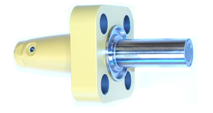
20.5.1 Pressure (PT)
Subsea pressure gauges typically operate using the force-balance technique, in which the current required by a coil to resist the movement of the detecting diaphragm gives a measure of the applied pressure. The diaphragm therefore does not actually deform and therefore devices can be built to withstand high pressures. Such devices can achieve an accuracy of +/- 0.15%, although the output current circuitry may reduce this to an overall error-band of around +/- 0.5% of full-scale.
Other devices operate using a similar technique in which the change in capacitance of a sensor element with pressure is detected and typically, accuracy of +/- 0.5% can be obtained.
However, it should be noted that further 'errors' are introduced into the overall system via the digitisation process between the sensor and its eventual display on the MCS. It is unreasonable to expect (and to specify) better than about +/- 2% for a pressure reading.
As pressure transducers are flange-mounted, they cannot be removed subsea if they fail. It is possible to specify a transducer with dual gauges fitted in one housing providing a dual redundant sensor.
Note that retrievable PT/TT sensor (intrusive PT/TT sensor from PRESENS) has been recently developed by TECHNIPFMC has been implemented on EGINA water injection Xmas Tree.
Figure 20.4 - Retrievable PT/TT sensor installed subsea (TECHNIPFMC Water Injection Xmas Tree of EGINA Development)
Higher accuracy can be obtained using quartz-crystal gauges and these are often used for high-accuracy Downhole Pressure Transducers.
20.5.2 Temperature (TT)
Some temperature sensors operate by measuring the output of a thermocouple, which is a simple device whose output is proportional to the difference in temperature between a hot and a cold junction. The hot junction is the one measuring the process and the cold junction is at the head itself.
To compensate for change in ambient temperature (cold junction) most such transmitters incorporate a compensating circuit, which needs to be co-located with the cold junction, but there is still a potential time-lag between the junction and compensation circuit which affects overall accuracy.
A resistance sensor has an element, which depends only upon the absolute temperature and therefore has no cold junction compensation. The disadvantages of a resistance element are its strength, but modern encapsulation techniques can improve this. They are also larger than the thermocouple probe, which can give it a slower response time. Modern sensors are typically made by film-deposition onto a ceramic substrate.
Temperature sensors present somewhat of a dilemma as regards their installation. In theory, the sensing element should be as close to the process fluid as possible. However, if the sensor were simply fitted into the production bore, there would be no other physical barrier between the process and the environment, other than the sensor itself. The usual approach therefore is to install a thermowell, or use a pocket drilled into the Tree Block.
Care must be taken in matching the size of the thermowell and the sensor probe - ideally, the probe should be just in contact with the wall of the process pipe (but not damaged by differences in tolerance or expansion etc.). Thermally conductive grease can improve this contact. Some installations do not consider this and therefore the temperature reading will be subject to the thermal inertia of the system.
The API standard for thermowell lengths is that they should protrude sufficiently into the process flow path to be within the mainstream turbulent flow. However in pipeline applications where through pigging is required, the thermowell must not protrude into the pipeline bore.
20.5.3 Combined Pressure/Temperature (PTT)
A design of sensor is available in which a Pressure and Temperature element are combined into one package. In this design, the temperature sensor is located in a probe, which is designed to be flush-mounted into the process pipe work. This also helps reduce errors due to hydrate formation. For sensors upstream of the Production Master Valve Regulations may however require that there is one or two block valves before the sensor, so, whilst the pressure measurement is unaffected, the temperature measurement may be subject to thermal inertia depending on its location.
The two devices are electrically independent, so the connector has to be a four-pin device. Care should be taken, however, to test that both devices are truly independent of each other as regards variations in power supplies on each device and temperature effects.

20.5.4 Choke Position (ZT)
Subsea chokes usually operate on the principle of stepping actuators adjusting the trim via ratchet and pawl mechanisms. Other types operate via a hydraulic motor. All however, require the position of the trim to be accurately monitored from the surface.
Positional transducers operate by a variety of mechanisms:
Conventionally an LVDT is used which measures the change in inductance of a coil when an armature is moved into it. This has no contacting parts and is very reliable. Proper electrical design can cancel out the effect of variations in supplied voltage. Again, the SCM supplier must supply the necessary energising voltage and detect the output variations and a special circuit is required.
The SCM or MCS must then calculate the choke position from the LVDT signal. A magnetic fluxgate device is a recent addition to the available techniques. In this, a fixed magnet connected to the rotating part of the choke actuator via a simple shaft causes electronic variations in a sensing circuit.
All the electronics are contained within one small can which can be bolted to the outside of the choke and retrieved if necessary. The output is available in digital or standard 4-20mA form, making interfacing with a SCM straightforward; no further computation within the SCM is required. With all of these sensors, care must be taken to match the available accuracy, hysteresis and resolution to the overall system requirements.
If the MCS is simply displaying choke position as a readout, then these are less important. If 'flow rate' is being calculated, whose value will depend on the Cv of the choke (i.e. position) as well as differential pressure across it, then they are of more importance.
If the measured position is being used as part of a choke-position control algorithm, in which the choke is moved until the measured position matches the desired position, then all of these are significant (for example, if hysteresis or resolution is too great, the choke might never actually reach the desired position, even when its direction of motion is reversed to attempt to approach it from the other direction, so it could continually 'hunt' for the correct position.
Systems that do suffer from this are obliged to put in an 'error-band', of +/- 1%, within which the choke can approach the desired band before its movement is stopped. The system then usually has to provide a means to 'single-step' the choke to allow the Operator to fine-tune its position.
20.5.5 Differential Pressure (DP)
A Differential Pressure Sensor is similar to a Pressure Sensor except that pressure is applied on each side of the measuring element; thus, its output is proportional to the difference between the two pressures. The devices are physically similar, as are their electrical connections (4 - 20mA).
Care must be taken to match the rating of the device to the expected range to be measured - sometimes this is difficult to achieve whilst still providing a device that can withstand the full process pressure across it.
20.5.6 Down hole Pressure/Temperature (DHPTT)
20.5.6.1 General
Sensors designed for use down-hole need to be as small and robust as possible, as they are required to operate in extremes of pressure and temperature. In addition, their data is usually required to be very accurate, for use in Well Test calculations.
To accomplish this, specialist suppliers of such devices use such mechanisms as quartz crystal gauges or capacitance gauges. The devices usually provide both pressure and temperature information.
The cable to the display device also needs to be as simple and as strong as possible, and is usually armoured. The space available within the tubing for the cable from the instrument to the Wellhead is quite small and the cables typically have a single central core and use the armour as the signal return/earth. At the Wellhead, the cabling is continued to the Subsea Control Module, where the data is processed and sent to the MCS via the telemetry link.
A single-cored cable presents a number of problems for the interface: any electrical current returning along the cable armouring could cause problems of corrosion, or to the corrosion protection system, if it is connected in such a way as to be in contact with any of the metalwork, or cause a potential difference across any metalwork.
In addition, as there is more than one parameter to be relayed (as well as the device itself to be powered), the data must be Multiplexed in some manner on the core. One technique was to operate the pressure and temperature elements in the sensor using alternately reversing power supply voltage, the current then representing the selected parameter. More recent techniques use a serial datalink, modulating the data onto the power supply.
Both methods require a special interface circuit within the SCM, together with correct data-handling protocol in the telemetry system. Most Suppliers have interface cards for the various makes of downhole sensor, but this is an area, which requires definition at the start of a Project to avoid later interface problems.
20.5.7 Sand Detector
20.5.7.1 General
Sand monitoring is used during all phases of Oil & Gas production. During the exploration phase, accurate knowledge of sand (solid particles), production is vital to select the most cost-effective method for well completion. The sand monitor can help to determine whether there is a problem with the formation; as perforation density can be evaluated, it is possible to gauge the need to gravel pack installation. Sand monitoring during drill stem testing can provide important background information to enable such decisions to be made.
After drilling is completed, sand monitoring will allow the effectiveness of cementing completion and the clean-up procedures to be evaluated. This can prevent costly damage to up-stream filters and other sensitive apparatus. The solids content in production can be measured to determine if gravel packing is required, and allows the effectiveness to be measured.
Sand erosion during production can be a significant problem with down-stream equipment, such as valves and chokes being badly damaged in relatively short periods. Significant deposits of sand in the topside production separators can cause production upsets, with liquid carry-over into other equipment. On-line monitoring can significantly assist in controlling these problems, preventing damage and build-up of sand, without greatly affecting production rates.
Detecting sand in the produced fluids can therefore be an important part of a proactive strategy for:
managing short term damage of vulnerable equipment (e.g. chokes)
managing long term damage of pipe work
warning of reservoir collapse
preventing separator level control problems
Sand detectors work either by measuring the acoustic energy (noise) generated when sand particles collide with wall of the pipe after flowing through a bend in the pipe work or by measuring the erosion damage of a target inserted into the flow. Systems are available from a variety of suppliers, such as (listed in alphabetic order):
Clamp On
EMERSON (ROXAR)
Cormon
CorrOcean
Fluenta
Milltronics (Stresswave)
Simrad
Acoustic sand probes are available as subsea instruments. As with downhole gauges, the processing of their data requires a specialised interface within the SCM and relevant software treatment.
Their suitability for a given application depends on:
requirements - qualitative or quantitative
the flowing conditions
the accessibility of the line
calibration requirements
the availability of an input signal (flow rate)
20.5.7.2 Operation
Non-intrusive acoustic devices are available packaged for subsea use. The Fluenta SAM 400 SR is based on passive acoustic detection of sound created by particles in process flows. The SAM 400 SR uses the signals generated when particles such as sand hit the pipe wall (located downstream of a bend) to detect and quantify particle production. Digital filters and the data processing unit remove flow-generated noise. An algorithm converts the noise generated to a measure of the quantity of sand being produced.
20.5.7.3 Installation
Installation can be carried out topside before deployment or subsea by ROV. The device is non-intrusive, being clamped onto the production pipe work in a suitable location.
Power and signals run through an oil-filled hose assembly with ROV connector or similar, using standard twisted-pair cable. Being clamped-on, this design is suitable for retrofitting, providing a 4-20mA interface to an SCM is available.
Initial set up is critical. i.e. determining what is background noise (signal from the detector which is not sand) and what is noise from sand production is very important, incorrect perception of too much sand production could have a negative effect on production causing the operator to “choke back” the excessively, however incorrect perception of low sand production could be very serious causing excessive wear on flow lines. For this reason it is normally necessary for the manufacturer to perform this task.
Particle velocity has a major effect on Acoustic noise. The change in velocity of the flowing medium i.e. oil/gas will have a proportional increase in the energy (Acoustic noise) created. Therefore during commissioning the velocity must be taken into consideration for field calibration to “tune” the ASD to the characteristics of the production flow i.e. whenever the choke is opened or closed the flow rate (velocity) changes which affects the acoustic noise from the sand. If the velocity is not automatically input into the sand monitor algorithm (topside) the operator would have to input the new value manually at every change in flow i.e. every choke operation. This is not advisable; therefore it is imperative to ensure change in velocity value is incorporated automatically into ASD software (MCS).
20.5.8 Pig Detector
20.5.8.1 General
Pigging operations such as pipeline cleaning and pipe work condition monitoring are dependent on reliable monitoring of the passage of pigs at various points in the system. Conventional detection methods involving devices inserted into the pipeline are liable to cause problems such as pipeline leaks, detector malfunction or pig damage. Pig detection sensors are available, several techniques are used; both are non-intrusive.
Magnetic Detector
Acoustic Detector
20.5.8.2 Magnetic Detectors
Magnetic detectors operate by detecting the passage of a magnet located on the Pig. Reed switches in the sensor are closed by the magnetic field and thus can be used to send a signal to the surface.
This type of sensor provides a single signal of presence only, with no further information available about pig direction, speed, etc., and must be positioned such that the best magnetic field is obtained from the pig’s magnets.
The signal must be ‘latched’ so that a rapid signal due to a fast moving pig is stored until it can be read by the MCS, and de-latched afterwards, either via a ‘reset’ signal or after a time delay. This requires a careful matching of sensitivity vs. latching time vs. system scan cycle time.
20.5.8.3 Acoustic Detectors
Acoustic detectors operate by detecting the acoustic energy created by the pig itself as it passes along the pipeline. They are also capable of determining the amount of pipeline debris being pushed ahead by a cleaning pig. Being acoustic, they can reliably detect foam, gel, polyurethane, brush, bi-directional, intelligent and spherical pigs travelling at velocities of 0.05 m/sec and above in oil, gas and multiphase flows.
[2] s. A zener barrier does not itself make a circuit intrinsically safe, it merely protects the integrity of an Intrinsically Safe circuit in the event of a fault by limiting the current flow to a safe level.


