
5 System Architecture
5.1 General
There are many considerations as to the selection of a control system type and of the system architecture. The options and ultimate choice and the recommendation of the system type can be a fundamental decision to an engineer with system experience, or a difficult task to an engineer with little or no system design, installation and commissioning experience.
The actual surface location at the mud-line of the wells is the principle factor in determining the field architecture and hence the subsea control system architecture.
Wells may be pre-drilled and suspended for later tie back, or a well may be drilled vertically as a satellite well for tie back at a long offset to an existing platform.
There may be a requirement for a long term production flowing test or extended well test requiring down-hole well data. If the well test was to prove additional reserves there could be the requirement to build in the flexibility to tie in a second well at some time in the future.
Another option is to drill a number of highly deviated wells in a cluster at the surface for tie back to a surface facility such as an FPSO.
A well could be drilled and completed in shallow water at a remote location requiring a simple control system design that can be maintained with low technical skills.
A well could be drilled and completed in deepwater requiring installation and hook up of the subsea control system by ROV, and with the requirement to control a smart completion.
The Topsides location may be a manned or unmanned Platform, or Floating Production, Storage & Offloading vessel (FPSO) or semi-sub.
The above are just a few of the scenarios for a subsea control system field development study. Each option requires a different solution.
![[Tip]](tip.png) | Tip Click these links below for access to 3D resources: |
5.2 Subsea
The subsea control equipment can be located on the Xmas Tree and/or other subsea structures that can be a manifold or template. For deepwater applications it is common for the SCM to be located on the Xmas tree for running and retrieval with the Xmas tree, or for running and retrieving on its own.
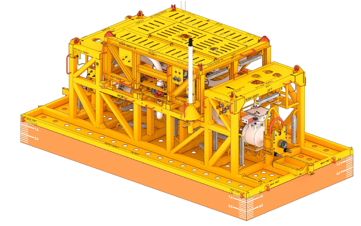
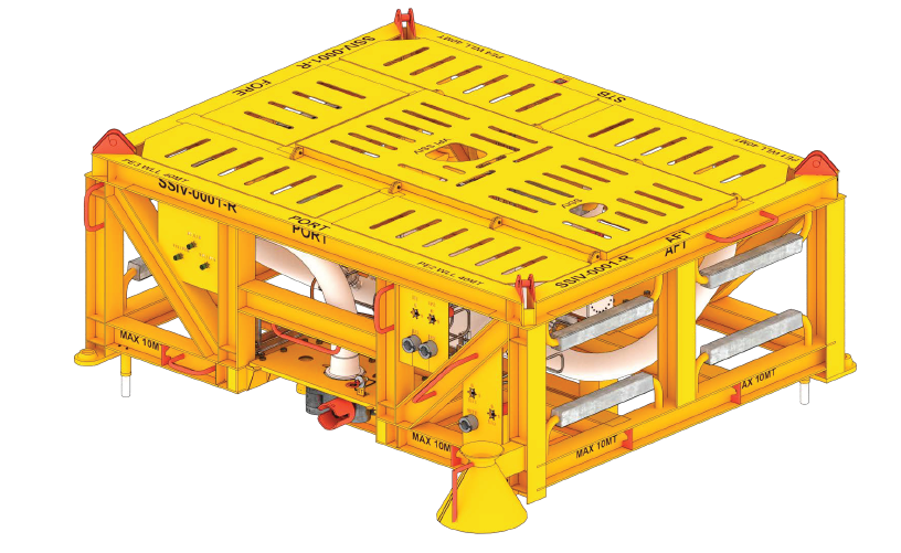
In some cases, control and monitoring functions may be required on subsea structures such as SSIV, FLET, ILTs, etc. which are remote to the typical subsea control system. In these cases, the control and monitoring equipment may be connected directly to surface where the equipment is located close to the facility and/or for safety related functions such as an SSIV where direct hydraulics are used to control the valve(s) and pressure/temperature sensors are connected to the control system topside over a dedicated umbilical.
In other cases such as remote ILTs which have electrically actuated valves or sensors these may be connected back to the nearest subsea control system node e.g. SCM over a long distance. In this case, consideration must be given to the electrical power supply and communications interface.
5.3 Hydraulic/Electrical Distribution
One common distribution method is via a single umbilical to a subsea distribution unit (SDU). From the SDU, the cable and hose jumpers distribute out to the SCMs. Where there are wells daisy-chained along a pipeline route, the feasibility is determined by the voltage drops between the modules and the range of input voltage that the SCM can work over. This can be overcome by including individual power cores within the umbilical for each SCM offset.
This may also be a consideration for signal on power systems where the signal loss due to noise filters limits the number of modules on the power pair. For systems with discreet signal pairs the theoretical limitation to the number of SCMs on a signal pair is limited by the number of unique communications addresses in the system manufacturer capability. In practice it is limited by the system offset, noise on the signal line, and signal bounce or echo (cable impedance matching).
Another common distribution method is via production (dynamic or static) umbilical connected directly to the Manifold through an Umbilical Termination Head (UTH).
5.4 Number of SCM Functions
Depending on the design, an SCM can typically provide between 12 and 42 (42 hydraulic functions are available on GE ModPod Custom) hydraulic control functions.
5.5 Hydraulic Distribution
The hydraulic distribution depends on the number of valve functions, the actuator sizes, and the frequency of valve operation whilst operating the system. Stored hydraulic energy subsea in accumulator bottles (Subsea Accumulator Modules, SAMS) is required to allow fast sequential opening of subsea valves without affecting the operation of other valves in the system. The accumulators are charged up by the hydraulic supply in the umbilical.
In deepwater applications, the external static head of seawater necessitates that there is an increase over the pre-charge nitrogen pressure in lesser depths making the use of accumulator bottles in deepwater not very efficient.
Hydraulic Intensifiers can be used to eliminate the use of a high pressure hose line in the umbilical. The intensifier is connected to the low-pressure (LP) hydraulic supply, which it boosts up to the higher hydraulic pressure, required for the SCSSV operation.
5.6 Electrical Distribution
For power distribution, electrical pin connectors are used to provide the best electrical efficiency over the distribution system. These can be two-pin connectors for a power pair, or four-pin for two power pairs/dual signal on power. A four-pin connector may also be used for a power pair and signal pair configuration for redundancy purposes. In services such as terminating signal pairs, multi-pin connectors can be used.
Where screened cables are used, it is common to use 3-pin connectors, the third pin being for the connection of the screen (it is important to maintain a correct screening philosophy throughout the system, to ensure adequate screening against electrical noise and to prevent the inadvertent formation of 'earth-loops', which generate more electrical noise. Similarly, a correct earthing philosophy for the electrical/electronic system must be maintained).
The telemetry systems used by the various Control Systems Suppliers communications systems are currently unique to each vendor, and may, or may not, be constructed according to an international specification. Therefore with the increasing requirement to communicate and control down-hole monitoring equipment, down-hole pumps, smart wells, multi-phase meters, etc, it is essential that system architecture in terms of communications requirements, power requirements and interface requirements is properly considered at the appropriate time.
System architecture in terms of reliability, power signal and hydraulic efficiency needs careful consideration. It is also important to consider the system hook up by ROV. In deepwater applications the deployment costs and the ROV time to hook up are principal considerations in the optimisation of subsea control system field architecture. Similarly, the connection systems themselves must be properly designed and tested for the application concerned.
5.7 Earthing
Earthing continuity is an important consideration in ensuring that all metal component parts are bonded to the rest of the adjacent structure to ensure adequate 'cathodic protection'.
For example, stabplate-mounted connectors and couplings should be strapped to the stabplate themselves and the SCM Mounting Base should be strapped to the Xmas Tree. Couplings on jumper hoses may require earth straps if there is any risk that they might be at some disconnected from their (cathodically protected) connection points.


