
17 Interconnections
17.1 Introduction
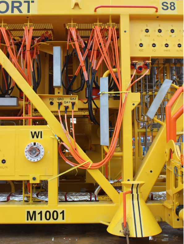
Jumpers are required to connect between the fixed items and installed items in the subsea system. The jumpers can be hydraulic, chemical, or electrical, or a combination of all three.
The jumpers connect between the umbilical SUTU and the SDU, the SDU and the SCM top or side face, etc. A jumper can consist of a single hose or cable with ROV connection or can consist of a stab plate assembly for multiple installation and hook up.
Stab plates can be guided and screwed into position or alternatively can be guided into position and secured with a clamp hub arrangement.
Jumpers for hydraulic systems are constructed from hose with hydraulic sealing terminations. For deepwater applications high collapse resistance hose (HCR) is required to prevent hose collapse. Alternatively steel tube may be used for jumpers, which also provides resistance to chemicals and eliminates chemical compatibility issues.
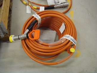
Electrical jumpers usually consist of a reinforced hose conduit outer sheath terminated to an electrical connector at both ends. Inside the sheath, single insulated copper cores are terminated to the conductor pins on the back of the connector water block and the conduit is filled with a dielectric fluid for integrity and also to provide a pressure balanced system for deepwater applications.
Jumpers can be hoses, steel tubes, steel tubes over sheathed, and cables bundled together, or alternatively a jumper can be laid up and over sheathed in a similar manner to the outer sheath of an umbilical.
17.2 Fixed Stab Plate (Inboard plate)
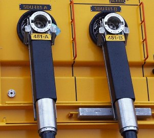
A fixed stab plate is required on the SDU, xmas tree or manifold structure to terminate the fixed hoses and cables and to interface with the flying ROV stab plate of the jumper assembly. The stab plate is usually mounted in a horizontal or vertical plane, and electrically bonded to the cathodic protection system of the mounting structure.
The stab plate has to be in a suitable location so that the ROV pilot can correctly identify it and fly in the ROV with the stab plate attached for installation and hook up.
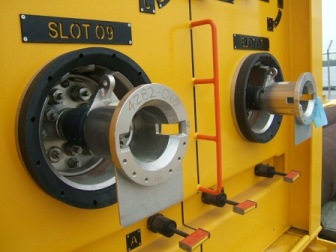
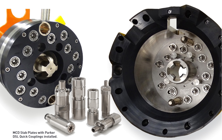
The stab plate is populated with male hydraulic couplings. There is a central receptacle for the entry of the lead screw arrangement for the male stab. Also there will be a guide sleeve for the male guide pin insertion, which provides the fine alignment of the plates prior to the mating of the couplers.
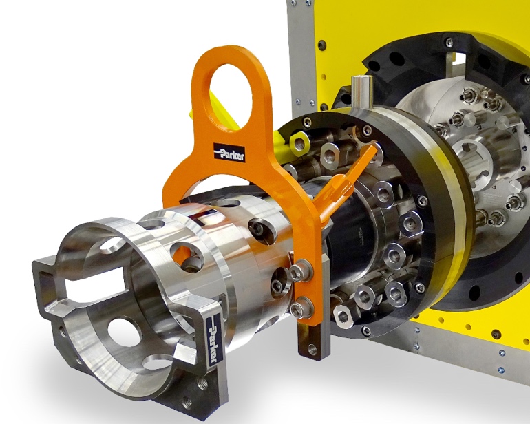
17.3 ROV free Stab plate
The ROV free stab plate comprises a flat plate populated with female hydraulic couplers. It can also include electrical connector receptacles.
Mounted to the centre of the plate is the drive screw assembly. The screw shaft nose provides the initial engagement with the fixed stab plate, and the lead screw provides the means of engaging the free and fixed plates together. The lead screw is made of dissimilar material to the threads in the fixed stab plate to prevent galling.
Mounted towards the top of the stab plate is a grabber / guide pin assembly. The guide pin provides additional guidance as the two plates come together and ensures the plates are aligned for coupler and connector engagement. The grabber shaft proves the means for the ROV to support the weight of the stab plate.
The torque tool and grabber interfaces are usually designed and manufactured in accordance with API 17H and allow the stab plate to be deployed using an Flying Lead Orientation Tool or an ROV Tool Deployment Unit (TDU).
A jumper termination bracket at the bottom of the stab plate provides a clamp for the jumper bundle for retention and strain relief for the hose terminations, and a location eye may be provided for a strain relief member.
Where steel tubes are used in a stab plate termination, there has to be consideration for the weight of the tubes due to ROV capacity and the bending radius of the tubes with respect to the location of the fixed stab plate.
17.4 Clamp Hubs
An alternative method of connection to the vertical mounted fixed stab plate described above is that the two end terminations to be connected face upwards. A U – Jumper with downward facing terminations is then lowered and guided onto the upward facing connections. Split clamp hubs with horizontal lead screws are then used by the ROV to finally mate the two sealing faces.
17.5 Electrical Jumpers
Electrical jumpers can be a single assembly with a single conductor pair or multi conductor pairs terminated into controlled environment connectors:
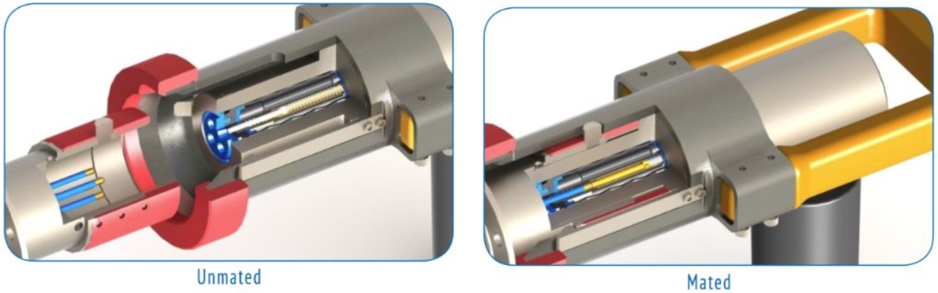
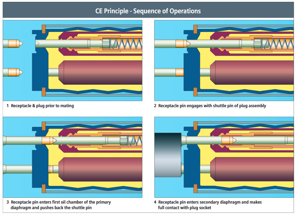
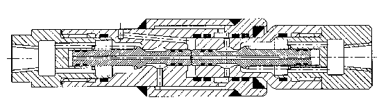
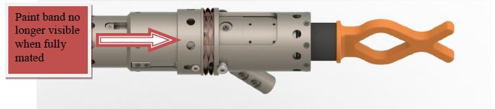
The electrical socket (female contact) is protected by its own oil bath, which in turn is protected by a primary oil filled chamber. The whole assembly is pressure balanced to minimise stress.
A shuttle pin prevents both water ingress and loss of oil when the connector is unmated.
During the connection, the male contact pushes on the shuttle and penetrates the oil filled chamber, being thus wiped clean of water before making contact with the electrical socket.
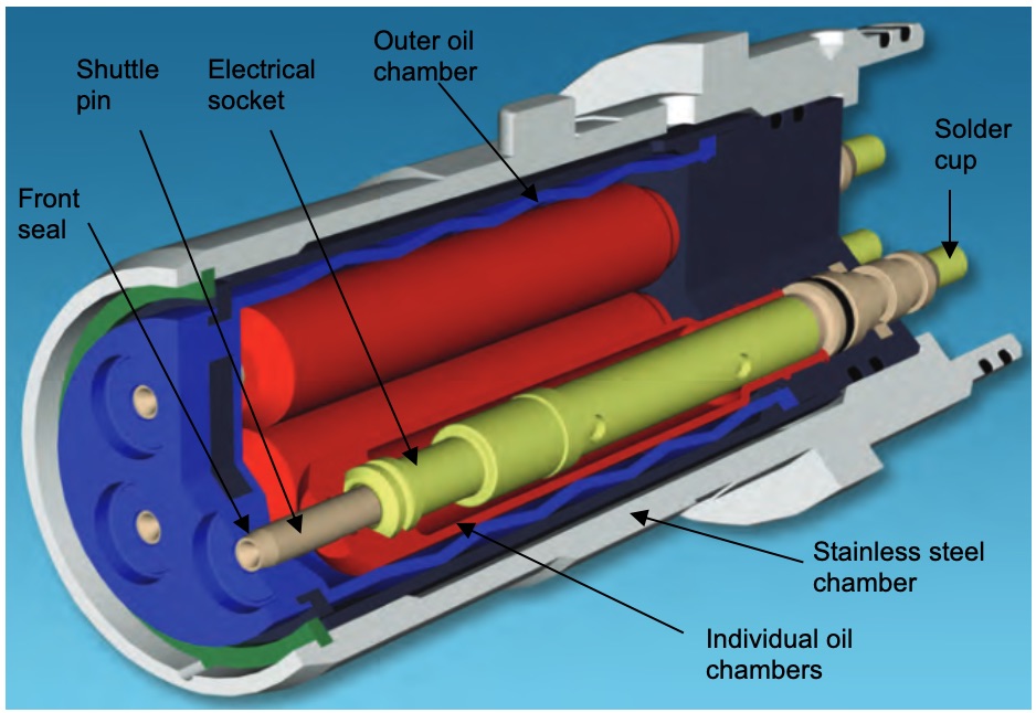
The free connector has an ROV grabber handle and the ROV pushes into the guide for the fixed connector. The guide has an orientation key and when the orientation is correct, the connector halves mate guided by a fine alignment guide.
The female conductor pins are enclosed in a pressure balanced dielectric oil filled controlled environment. During make up the male connector pins pass through a wiper seal and through dual redundant compensated barriers to ensure that final make up is within a totally oil filled environment. After the connector is fully mated the ROV releases the grabber handle. Removal is the reverse procedure.
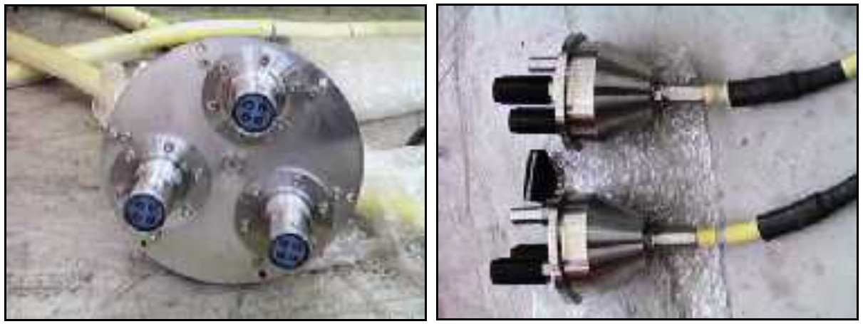
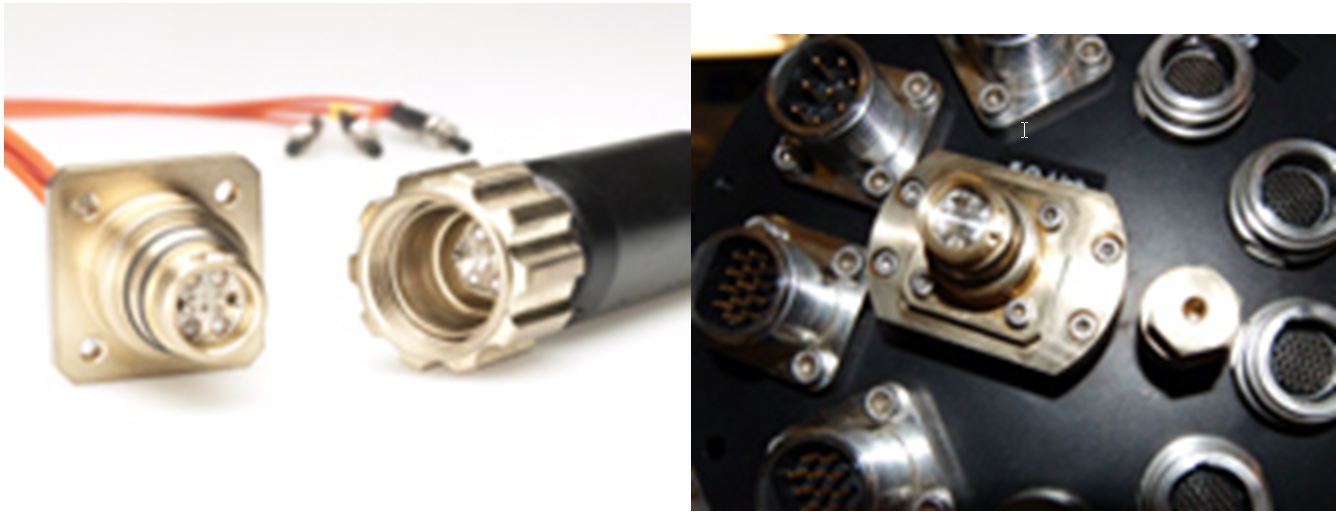
It may be necessary to provide a jumper to connect several transducers into a multi-pin connector at the bottom of a subsea control module mounting base. The illustration below shows a jumper with a flange mounted termination with connections for three single connectors which locates on a vertical face of a SCMMB, which has a cable conduit exit at the rear, and the other jumper end terminates in a multi-core connector in the module mounting base.
The main subsea (mateable) electrical connector manufacturers are:
SIEMENS (Tronic products)
TELEDYNE (ODI products)
SEACON (HydraElectric)
For high power application, three connectors are required to complete the three-phase circuit.
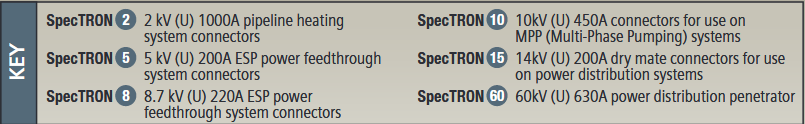
SIEMENS has developed SPECTRON 60kV (630 A) which is primarily for use on subsea electrical transmission and distribution schemes. See below different SpecTRON medium and high voltage wet mate connectors capacity and applications.
Electrical connectors are used for power, control and data transmission as further detailed in document "Umbilicals" Ref. [68]which is part of the deepwater field development reference book.
17.6 Hydraulic Couplers
The hydraulic couplers for deepwater applications need a strong enough spring to seal against the external pressure head in order to prevent the seawater contaminating the hydraulic fluid, but also to be of a design where only a low pressure force is required for make-up.
There are couplings available that require a low force only for make-up, and these are available with dual redundant resilient seals, and with a combination of resilient and metal seals.
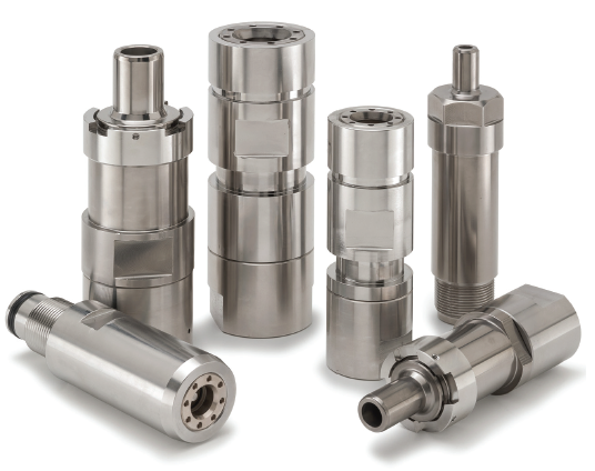
For deepwater applications a fully pressure balanced coupling is preferable. These are fairly new concepts, but are available in single coupler pair design, and also the four coupler hydraulic circuit HydraQuad™ design. The single pair is a resilient seal design with a porting design that allows an inherent pressure balancing across the poppets, which provides a pressure assistance to the spring closure force when the coupling is disconnected. The HydraQuad™ design uses a combined metal and resilient seal arrangement acting in a shear seal arrangement as the coupler mates and disconnects.
Both designs use the principle that the flow path is radial and hence produces no resultant separation force.
It is important that there are adequate flow paths through hydraulic couplers to ensure that adequate hydraulic response times are achievable. Also that the poppets are balanced to prevent the poppets being driven hydraulically from the central open position and sealing against one of the seal faces.
The female couplers are usually assembled into a hydraulic jumper stab plate in order that they may be retrieved and the seals replaced if necessary. The female couplers are assembled so that they are floating on the plate to allow for any manufacturing tolerances.
The back of the connectors have to be terminated to screw on hose termination couplers or by screw seal or welded assemblies for the termination of steel tubing.
JIC hose terminations which swage inside the central core tube of a standard thermo-plastic hose can only be used when the hose can be maintained full of fluid of a specific gravity equal to or similar to the specific gravity of seawater. This is to prevent collapse of the hose in deepwater applications.
Alternatively high collapse resistance hose (HCR) with a spiral flexible metal former under the core tube can be used. The flexible inner core is designed to withstand the external seawater pressure and to prevent the hose core from collapsing. The HCR hose requires a different type of coupling which has a welded construction. The metal former inside the coupler slides inside the spiral hose support and seals by swaging onto the outside of thermo-plastic liner.

When stab plates are densely populated, it can be difficult to turn and orientate all of the hoses through ninety degrees and into the hose/cable restraint. Right angled connectors are used to orientate the hoses into the clamp. It may also be necessary to have these connectors of stepped heights in order to allow hose make up and to avoid tight bends or kinking of the hoses.
For larger ID, monobore coupler connector can be used (Unitech connector or Walther Praezision coupler).
17.7 Fibre Optic Jumpers
Fibre optics are now becoming more commonly used as subsea distances and depths increase. However fibre optic technology is well proven in the telecommunications industry and the subsea fibre optic has been proven and is in use in seismic applications at greater depths than currently required in the oil industry.
The fibres themselves are manufactured into a steel tube conduit. The fibres are terminated into the back of the connector where the fibre is ferruled and polished and as the termination assembly is a precision fit the fibre is routed in a low stretch flexible conduit in the same manner as an electrical jumper but requires jointing. The joint box size or fibre management system is adequate to accommodate the bending radius of the fibre in order that any excess fibre can be coiled. The joint is made using a low loss fusion splice that is protected by re-coating the fibre or by using a heat shrink splice protector. The compensation oil used for fibre optic jumpers is silicone oil that is known not to degrade fibre optic properties.
The connector design is such that the fibre ends are protected in the compensating oil environment and not exposed for make up until the two connector outer shells are made-up. The two fibre halves are aligned using a sleeve which guides the outer ferrules to align the fibres, and when the fibres touch one is spring compensated to allow for any over length tolerance.
Hybrid connectors exist capable of packaging a combination of electrical conductors and single fibres in an 8 way shell but it is not widely used on subsea equipment.
There are also fibre optic connectors available with penetrator feed through for connecting to downhole gauge cables.
17.8 Jumper Deployment
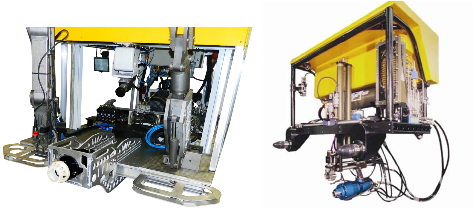
As jumpers are not usually armoured and rely on their own inherent strength a deployment tool or device is used to assist the ROV. This can be a deployment frame, basket or subsea pallet where the jumpers are laid onto in a “figure of 8” arrangement. The deployment frame is laid on the seabed in mid position and the ROV firstly picks up one end for installation and hook up, and then takes the second end for installation and hook up.


An alternative to the above is when the jumper is pre-installed on the jumper or subsea structure in a figure of 8 configuration hanging vertically, and the ROV pulls off the loops from the hanging device as the termination is being carried for installation at the second connection.
It is essential that jumpers are designed in terms of size and weight around the planned installation method. It is necessary to understand the size and capability of a work class ROV in order to correctly specify jumpers and their terminations.
17.9 Jumper Retrieval
Both single connectors and stab plate jumpers are precision assemblies with tight manufacturing tolerances for ease of assembly and good fit when new. If a failed jumper has to be retrieved for replacement, it is essential that the jumper also comes apart.
When connectors have been in service for some time they can be covered in marine growth and also subject to calcareous growth on outer surfaces. This can make them hard to disassemble.
Connectors and hydraulic couplings must be designed taking retrieval into consideration. Some electrical connects have a collet latch with shear pins which allows the latch mechanism to breakaway if excessive retrieval loads are required. The latches are easy and cheap to replace.


