
19 Subsea Control Module (SCM)
19.1 General
The SCM is an electro-hydraulic module that provides the hydraulic power to open and close subsea valves and chokes on Xtree’s and manifolds. It also provides electrical power and communications to chemical dosing valves and subsea instrumentation and communicates this information to the Topside operator workstation (OWS) via the MCS/SCU.
Commands from the MCS/SCU (transmitted via the umbilical) are processed in the Subsea Electronic Modules (SEMs) inside the SCM.
SCM’s are installed onto SCMMB’s which are assembled on to Xtrees base or Manifold structure.
All vendors have standardised their designs for SCMs. Some vendors have more than one standard design and other vendors have engineered a universal design in which the build specification dictates the actual equipping of the module in terms of control and monitoring.
The design is suitable for use both on the production, gas injection or water injection Xmas trees, or to control manifold valve functions however in most application Prod SCM, WI SCM or MCM are not interchangeable.
The SCM design is normally retrieved using a purpose built Module Running Tool. Designs differ depending on module design and project requirements, water depth, environmental conditions etc.
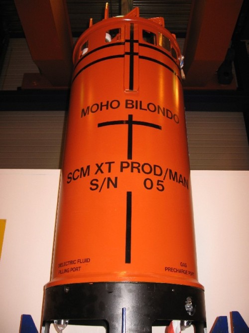
19.2 Housing
The SCM housing is a fully fabricated welded construction in painted carbon steel. A lift mandrel penetrates from the upper housing for lifting and installation purposes. A purpose built running tool is required for installation as current SCMs are too large and heavy for an ROV to free swim and install without added buoyancy.
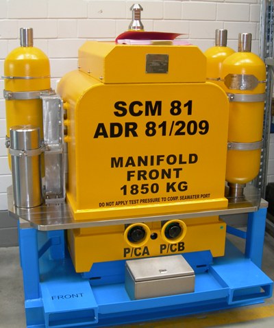
An example a SCM weight and dimensions for an FMC SCM Mk3 is given below:
Weight in air / water: 1800kg/1120kg
Overall height: 1777mm
Diameter: 855mm
19.3 Mounting Base
An SCM is designed to fit onto a dedicated Mounting Base (SCMMB). This is described in detail in section 20. The SCM will only fit on the mounting base in the correct orientation. The orientation can be achieved with guide pins that prevent incorrect mating, or with a centre helical guide-pin, that will orientate the SCM on landing.
The SCM incorporates a mechanism for locking down onto the module mounting base after installation. This can be ROV activated by a special tool which pushes the SCM down onto the mounting base and locks it in position using an over centre mechanism that pushes up onto the lower face of the module mounting base, or alternatively it can be a twin screw lock device.
19.4 Interfaces
There is a substantial force to overcome the mating force of self-sealing hydraulic couplings in deepwater, and pressure balanced couplings are used for this requirement.
The SCM will have 4-20mA driver circuits for monitoring external sensors for pressure, temperature, and choke position on the Xmas trees.
Optional circuits provide inputs for downhole pressure/temperature gauge monitoring, by installing the gauge in a mandrel in the production tubing string.
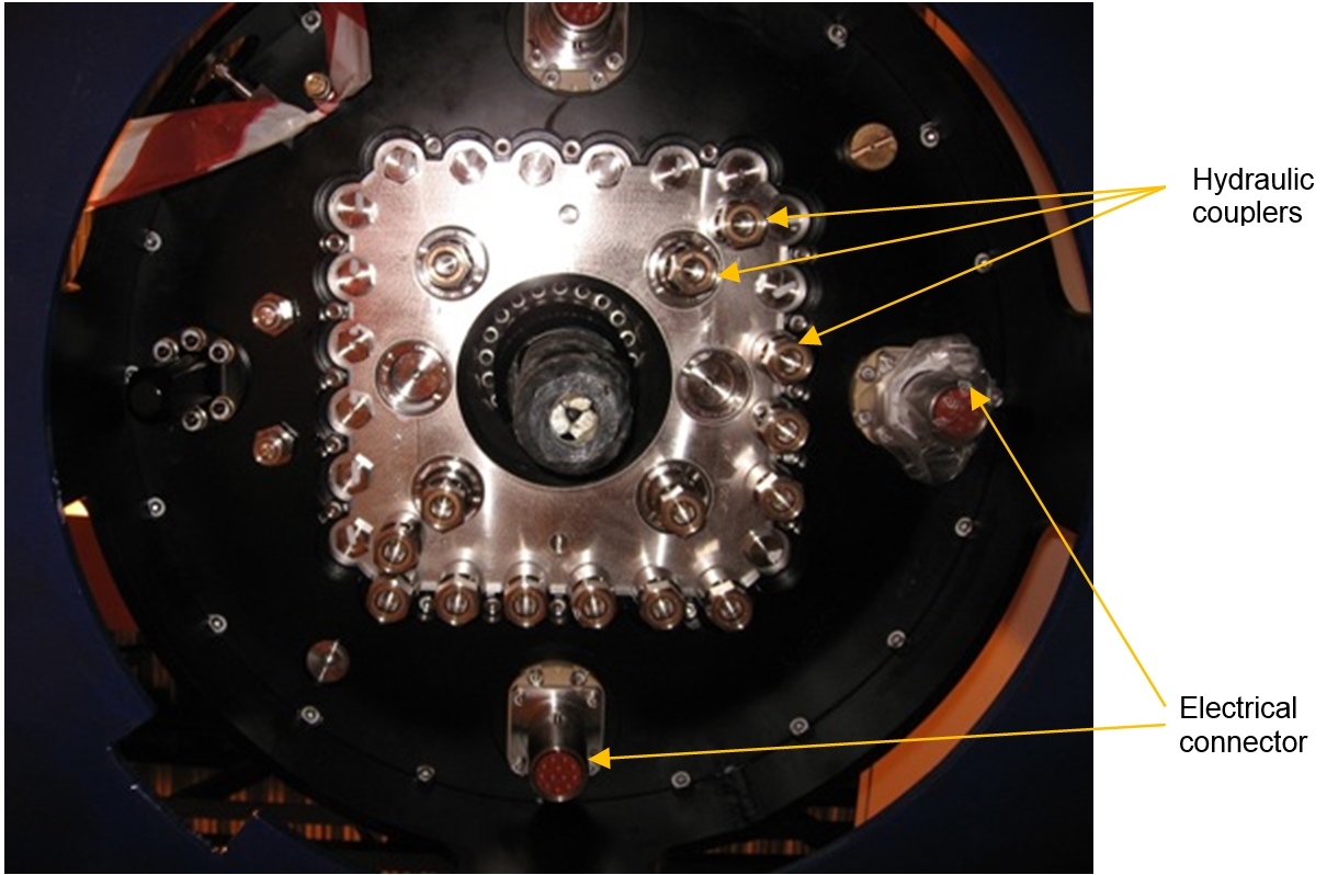
19.5 Connections
Additional monitoring functions can be provided for items such as Sand Detectors, Pig Detectors, Multi-Phase Flow Meters, etc.
The SCM base plate is penetrated externally to its lower face by the electrical and hydraulic connectors, (see figure below) and the guidance and locking mechanism.
19.6 Hydraulic system
Dual LP and HP hydraulic supplies feed into the SCM from the HPU through the umbilical(s) and HFLs. The supply lines are fitted with 3µm Filters and then feed into the manifold block which directs fluid to the Directional Control Valves (DCVs). A selector valve (called switch-over valve) on LP and HP supply lines provides the operator with a means of selecting line 1 or line 2 as required.
Pressure transmitters are fitted in LP, HP supply and return lines. The different pressures are displayed topside at the operator station via the MCS/SCU.
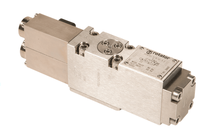
The LP and HP supply manifolds are of a modularised design which is fitted with the required number of Directional Control Valves (DCV’s) as required by the project and the SCM purpose i.e. whether it is Production or Water Injection SCM. The type of DCV will differ depending on the application (switch-over valve, tree valve actuation, choke actuation, continuous hold valve for HIPPS system).
The ports of the DCV’s are switched using a metal slide, which has metal to metal seals to the valve body. The metal slide has a spring to fail safe closed. To open the valve the open solenoid valve coil is energised and its hydraulic pilot directs fluid on the opening end of the slider. The slide moves and compresses the return spring, and in the fully open position connects the SCM incoming hydraulic supply to the subsea valve actuator causing the valve to open. The output from the DCV has a self-latching circuit so that the valve will remain open with the open coil de-energised.
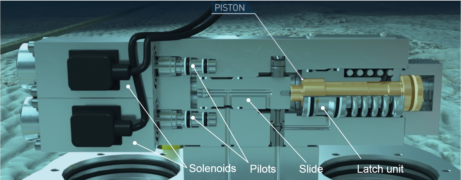
The DCV will fail closed on loss of the hydraulic supply, or fail closed on energisation of the close solenoid coil. Energising the close solenoid directs a pilot hydraulic supply into the return spring cavity, and onto the closing end of the slider.
The commanded output functions from the Directional Control Valves exit via hydraulic couplers. The surface commands energise the respective solenoid valve coils to open and close the valves. Pressure transducers (4-20mA) mounted on the Directional Control Valves detect pressure and confirm actuation back to the MCS/SCU, confirmation of valve opening is displayed at the operator station.
Although the SCM hydraulic system is designed to fail safe closed on loss of hydraulic supply, with long offsets and in deepwater applications, the extended time for valve closure may be unacceptable. If this is the case, the SCM may be fitted with a high flow hydraulic quick-dump valve for faster shutdown.
DCVs are available in seawater tolerant materials, however materials selected for seawater tolerance may not provide the best technical solution in terms of long term reliability.
For solenoid valves in particular, the electrical performance due to the coil and Faraday cage, and the mechanical performance in terms of the valve seat, ball, and plunger need careful consideration
19.7 System Design
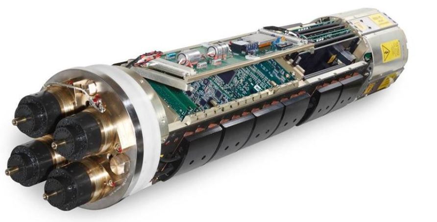
For deepwater applications dual redundant Subsea Electronics Modules (Dual SEMs) are invariably used. A SEM consists of a one-atmosphere nitrogen filled pressure vessel housing containing the control and monitoring electronics. The SEM is designed to stand external pressure and to keep the electronic components in a dry one-atmosphere environment that they were designed to work in.
A cover with barrel-seal O-rings seals the housing, and a cable penetrator or multi-pin electrical connector is used for the cable entry.
19.8 Electronics
The SEM contains circuit boards for the power supplies and conditioners, modems for communications, analogue drivers, solenoid valve drivers, and a ‘house-keeping’ monitoring capability to ensure that the electronics are working properly and provide alarms to the operator if a problem is detected.
If additional electronics are required for equipment such as down hole pressure and temperature monitoring, this can be included in the SEM if there is sufficient space available, or alternatively in a separate housing (called Downhole Interface Unit DIU for downhole sensors).
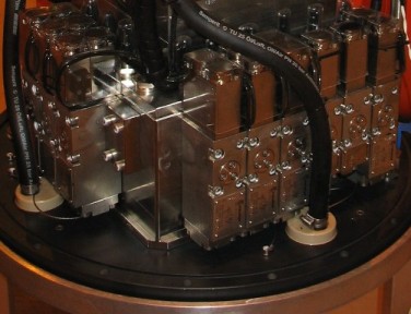
19.9 Construction
The SCM is built up from the base plate with the manifolds, DCV’s, filters. The SEMs are installed and wired to the incoming power and signal connectors and wired to the internal transducers. The outer cover bolts into place over the SEM’s and seals with the SCM base plate, and the housing is then oil filled using dielectric oil. The housing is pressure balanced for pressure compensation using compensation bladders.
19.10 Corrosion protection
The SCM does not usually have any cathodic protection (CP) of its own. It is electrically bonded to the SCMMB using spare pins in the mating electrical connectors. The SCM is protected by the CP of the Xmas tree or manifold where it is located.
19.11 Pressure Compensation
The oil filled pressure balance SCM housing requires a compensation system to cater for the change in volume of the dielectric oil fill within the SCM for shipping and handling after FAT, through to installation. Compensation bladders are used for this purpose.
The calculations need to consider not just the change in volume due to depth, but also the change in volume due to temperature difference from ambient to the seabed, and also the effect of any trapped air in the compensation system.
The correct sizing will ensure that the bladders are not over extended, which can cause rupture.
The oil/seawater interface should be at the bottom of the SCM, and in the event of bladder rupture the seawater should maintain the oil within the SCM housing preventing seawater ingress.
19.12 Return Line Compensation
During SCM deployment subsea and hook up in deepwater, there is a possibility of seawater ingress into the SCM hydraulic system via the hydraulic couplings. If this occurs there is the possibility of subsequent valve corrosion if the SCMs cannot be flushed immediately after installation.
To prevent this, a return line pressure compensator is required within the SCM. The pressure compensator, which is externally pre-chargeable, maintains a positive pressure within the SCM internal hydraulic system during SCM deployment and hook-up, thus preventing any seawater ingress.


