
7 Master Control Station (MCS)
7.1 Introduction
Any electro-hydraulic Multiplexed subsea control system requires a topsides unit to provide the necessary interface between the Operator and the subsea equipment. As the system operates using electronic messages between the surface and Subsea Control Modules (see also Chapter 19, Subsea Control Module (SCM)), some form of communications sub-system is required to perform this function. In addition, an interface with the Topsides Operator and/or Topsides Supervisory Control System and ESD system will also be required.
The Master Control Station is the generic name usually given to the suite of equipment that performs this function. It will usually comprise of one or more racks of computer and interface equipment, (located in an Equipment Room), and an Operator Console (also called Operator WorkStation OWS) located in the Central Control Room (CCR). Some suppliers name this equipment the Subsea Control Unit (SCU), the purpose and function is broadly the same.
Power to the subsea system is provided by a separate unit, the Electrical Power Unit (EPU), which is described in its own section, Chapter 8, Electrical Power Unit (EPU), but is sometimes incorporated within the MCS suite of cabinets (can be called the SPCU Subsea Power and Communications Unit depending on supplier)
7.2 Components
7.2.1 Computer
The heart of the MCS is inevitably a computer, or more often two computers operating in a master-slave configuration in order to provide a high availability.
The computers used were originally often a proprietary unit manufactured by the Supplier, however in recent years commercially available machines have been used as confidence in their reliability has improved. Nevertheless, the use of commercial PC-based computers is still mostly restricted to test equipment, or to proprietary industrialised-PC equipment. The advantage of using such equipment is evidently the availability of support software and corresponding economy of cost.
The importance of regular data from the subsea system and the need for high availability of Emergency Shutdown capabilities, tends to dictate at least a dual-redundant system. With this, two computers are operated simultaneously, continually exchanging data such that, if one fails, the other can immediately take over without significant loss of data or (more importantly) without causing an unwanted interruption of production or inadvertent shutdowns.
A ‘watchdog’ circuit monitors the correct operation of each computer and switches to the other if one fails; this is usually a sub-system using signals from both the hardware (power supplies, temperature sensors etc) and software (signals issued once per software loop) and can therefore be quite sophisticated. It must also allow manual selection of each computer for maintenance purposes but should also prevent a faulty MCS from gaining control of the system. Usually, a three-position key switch is provided with Computer ‘A’, ‘B’ and ‘auto’ positions.
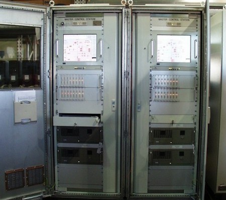
7.2.2 Cabinet
The MCS computer and associated input/output circuitry and hardware are usually housed in a 2 or 3-bay 19” standard rack. At least one of these bays is taken up with the input/output terminals (typically ‘KlipponTM’ terminals), which may incorporate Zener-diode safety barriers where signals are connected to higher risk areas. The cabinets may also include a small Video Display Unit and keyboard, for maintenance purposes (which may also double as a standby control console). Fan assemblies provide localised forced-air cooling. The racks also contain the Watchdog circuit (for a dual-computer system) plus local controls.
Some Suppliers may also incorporate the subsea power supply (EPU) in these racks, if only a small number is required for the size of the Field concerned. However, normally the EPU is a separate unit.
It is usual to allow for a degree of expansion in the system, as the MCS computer and telecommunications system can usually operate a large number of wells, (albeit with a reduced field scan time).
It is usually only necessary to add additional Power Supplies and modem units to expand the field (as far as the MCS is concerned, although there may be far greater impact elsewhere in the form of additional umbilicals, subsea jumpers etc.), so the racking hardware usually has some spare slots available, concealed by blank panels.
The design of the rack is also influenced by its installation location – if it must be mounted against a wall, then rear-access is not available and the racks must be designed for front access, usually involving swing-out card-frames, which makes the racks larger than otherwise required. Similarly, the method of access for all the cabling must be taken into account, as top-entry and bottom-entry cabinets affect the layout of the internal components.
7.2.3 Displays & Controls
A Operator Work Station (OWS) (sometimes referred to as a Man Machine Interface MMI) will be located in the Central Control Room (CCR) accompanied with standard PC keyboard and mouse.
Dual OWS can be included, if space allows, to allow automatically switching from primary to backup computer in the event of failure of the former, but in this case there is often a second smaller WorkStation doubling as a Maintenance WorkStation (MWS) housed within the MCS cabinets themselves. This will usually give access to all the main Operator interfaces as well as any lower-level maintenance functions
A single OWS is also acceptable if there is also a data link to other Topsides computers, such as to the main SCADA/DCS, allowing subsea data to be displayed elsewhere and (often) control of the subsea system itself. Some systems utilise a separate PC or lap top for this purpose, referred to as the ‘Smart Tool’. This is basically a commercially available PC which houses the MCS software programs and test programs and can be used for system maintenance tasks independently from the operator OWS.
A separate 'Status Panel' is sometimes incorporated into the Console or the MCS Rack itself, to provide hardware control of the Master/Slave Computers and house indicator lamps showing the status of the MCS (online/offline etc.). Hardware ESD buttons may also be incorporated.
7.2.4 Printer
An MCS is usually provided with an Events/Reports Printer, usually a standard dot-matrix or Laser printer, which prints events, alarms, control actions etc in real-time, thus providing a hard copy of all actions and readings.
The same printer can also double as a report printer; the format of the reports being as selected during the design stage but typically comprise a summary of alarms and events over the previous 24 hours.
Care must be taken during system design to ensure this Printer does not print unnecessary fine detail, as there is a large amount of data within a typical system and the printouts can very soon become very copious, to the extent that they become ignored, or the paper runs out, or it becomes difficult to find the event which actually triggered other events. Defining the type of event to be printed, or ensuring that finer detail can be recalled if necessary, also requires careful system design.
All data should be stored within a buffer in memory so that it is available for later printing if the printer is unavailable due to lack of paper, off-line etc. Other management utilities should be available to select the data required, clear a full buffer, stop un-required printouts etc.
7.3 Interfaces
7.3.1 Subsea Communication
7.3.1.1 General
The Subsea Control Modules communicate with the surface via electronic means. The method of communication must be considered as two parts: the carrier system and the protocol used.
There are two ways to convey information from one place to another:
analogue
digital
7.3.1.2 Analogue
'Analogue' means to convey information such that the voltage or current is in direct proportion to the value of the signal - this is the method most frequently used to obtain information from, say, a sensor, typically using a "4 to 20mA" loop in which the value of the current varies between 4mA and 20mA according to 0% to 100% of the full-scale reading. However, one pair of wires is required per sensor. This is adequate where only one sensor is involved but for a complete subsea control system comprising perhaps 5 sensors per SCM and 20 SCMs, this is clearly impractical.
In an analogue system, the carrier is the voltage or current in the wire and the value of that voltage or current conveys the information.
7.3.1.3 Digital
A "Digital" system converts these analogue signals into digital form, i.e. a sequence of binary 'data bits' where, say, 0000 (0 in decimal) represents zero and 1111 (15 in decimal) represents full scale, so a 1-bit change would represent 100/16 = 6.25% of full-scale (say, 312.5 psi for a 5000 psi sensor). In practice, a better resolution is obtained using more bits (typically 12 to 16). In order to achieve even greater resolution from Down hole Pressure Gauges, often 20+ bits are used, but for the majority of ‘normal’ sensors 12 bits (range of 4096) suffices, as there is little point in obtaining a fine resolution if the accuracy of the gauge itself does not match.
In addition, a digital interface allows instructions to be sent between the topsides and subsea systems, as well as data. A suitable 'protocol' must therefore be selected such that each unit 'knows' when the binary information is meant to be 'data' or 'instructions'. A very simple uplink protocol (SEM to MCS) could be:
START BITS | ADDRESS | SENSOR 1 | SENSOR 2 | SENSOR 3 | CHECKSUM |
0000 | 0001 | 0010 | 1100 | 1010 | 11001 |
In this protocol, the receiver sees the first 4 '0's and recognises it as the start of a message. The next 4 bits are an 'address' and if the receiver has the same address, it will continue to expect data for itself. The next three sets of information are readings from sensors 1, 2 and 3. The final bits are a 'checksum', which are calculated by the Transmitter and appended to the message.
The Receiver also calculates what it expects the Checksum to be and if they agree, accepts the whole message. Once the Receiver has recognised a command intended for it, it will reply with the data requested, or with a message confirming the requested action. This latter method is termed ‘check-before-operate’ and is used as a double-check that the SEM does not select and activate the wrong valve when commanded to open or close a valve (see SCM section Chapter 6, System Outline for more details of ‘check-before-operate’)
So a typical downlink command (from MCS to SEM) and uplink response (SEM to MCS) might be as follows, where the shaded cells (cells in grey) represent a long digital message, typically comprising:
MCS COMMAND (Shaded block in 'MCS Command' table below) | ||||
START BITS | ADDRESS | COMMAND | STOP BITS | CHECKSUM |
0000 | 0001 | 0010 | 11 | 11001 |
- | - | - | - | - |
SEM REPLY (Shaded block in 'SEM Reply' table below) | ||||
START BITS | ADDRESS | COMMAND ACKNOWLEDGE | STOP BITS | CHECKSUM |
0000 | 0001 | 0010 | 11 | 11001 |
MCS Command (shaded block = digital message as above) | |||||
Request Status | - | Operate Valve (Check) | - | Operate Valve (Operate) | - |
- | - | - | |||
SEM Reply (shaded block = digital message as in second above) | |||||
- | Status | - | Echo Valve Address | - | Confirm Operate |
- | - | - | |||
This is a very simple example and in practice, longer and more complex message strings are used, but the principle remains the same. The protocols are sometimes also designed to match the particular Subsea Control Module hardware design, and may allow further error-checking, redundancy and sometimes error-correction.
These protocols were developed over the years by each Supplier to suit its particular system or to meet a specified requirement.
A typical message cycle for a whole field (of 3 SCMs in this example) might then be:
MCS Command | |||||
Request Status SCM 1 | - | Request Status SCM 2 | - | Request Status SCM - | - |
- | - | - | |||
SEM Reply | |||||
- | Status SCM 1 | - | Status SCM 2 | - | Status SCM 3 |
- | - | - | |||
In practice, this ‘scanning’ for the parameters of a complete system can take a certain amount of time, as only one SEM can be addressed (and can reply) at a time. A typical scan of a 10-well subsea system can take about two minutes, but this is very dependent on the Supplier’s telemetry system, protocol, number of SCMs involved etc, so this can only be a ‘rule of thumb’
This type of message exchange system is termed ‘half-duplex’, as an SEM only replies when it receives a message intended for it, and the MCS waits to receive a reply from subsea once it has sent a command, thus there is traffic on the telecommunications link in one direction only at any time.
With modern telecommunications methods, full-duplex (i.e. traffic in both directions simultaneously) is perfectly possible but is not usual in subsea systems, as a typical subsea system is never required to operate at such a high speed, or do many things simultaneously. In practice, the Operator will perhaps operate one valve only, then wait for pressures and temperatures to stabilise before proceeding to perform the next valve operation.
Similarly, high speed data links are also not usual for the same reason, and the above protocols typically operate at 1200 - 9600 bits per second, which is very slow by modern standards (a typical PC modem to the Internet can now operate at 56,000 bits per second, by way of comparison).
Faster data links require more sophisticated circuitry and careful attention to cable technology, shielding, impedance matching etc, so are not really necessary unless the system is required to handle fast control loops or video data. In the former case, for, say, subsea pump control logic, it is not necessary (or desirable) to include the MCS in the control loop when the SEM itself is already a control board and can therefore handle local subsea control.
7.3.1.4 Carrier for Digital Signals
In a 'digital' system, therefore, the information is conveyed by binary data, a sequence of '1s' and '0s' that can be transported by a variety of electrical methods:
The carrier is the electrical method used to convey the data. There are a number of ways of electrically conveying information, some of which are listed below:
Direct current (DC)
The digital information is carried as a voltage or current whose value varies from one fixed level to another depending on whether it is a '1' or a '0'. It is a 'baseband' system in which a single electrical pulse represents the '1' (and zero volts a '0') and is therefore fast but requires accurate transmission and reception electronics.
This method is used in some systems, but consideration must be made for the length of the umbilical between the Transmitter and Receiver, as DC signals are easily attenuated by the cable, and 'cross-talk' between different cores in the same umbilical can cause reception problems. The shape of the digital pulses becomes altered by these umbilical characteristics, (as a square pulse actually requires a very wide bandwidth to be accurately transmitted) and there is then a limitation to the frequency (bit-rate) that can be achieved.
It is often tempting to use this type of carrier when large diameter copper cores are already being used in the umbilical for other purposes (such as down hole pumps), but again, such equipment can cause severe interference (voltage spikes) on the cores and hence impair reception.
Alternating Current (AC) systems.
Alternating current systems are more prevalent, as various methods are available to carry the information to reduce the effects of noise. The most widely used method for subsea systems is 'Frequency Shift Keying' (FSK) in which the frequency of the carrier is altered between two different values to indicate a '1' or a '0'.
This is not a baseband system as a number of cycles are required to transmit a '1' or a '0' but the detection and transmission equipment do not require such accurate operation. The information is transmitted using only two frequencies, chosen such that they are within the known passband of the umbilical and are therefore not attenuated too much (or at least the attenuation can be calculated).
A further advantage of such an ac system was originally that it could be used in conjunction with 'Inductive Couplers', which would otherwise block dc signals.
Other methods of encoding exist, such as Phase-Shift Keying, Quadrature-Amplitude-Modulation, etc., but the goal is to transmit the digital stream of information between the MCS and SCM and vice-versa.
The device which converts the digital signals into the form suitable for transmission along the umbilical wires is the Modem (Modulator-Demodulator) - such modems are used nowadays in PCs to connect across ordinary telephone lines to the Internet, or in Fax machines to send and receive faxes; the principle is the same.
Some Suppliers of Subsea Systems do use commercially available modems/protocols, thereby reducing the costs. Modems are very sophisticated devices nowadays, with built-in error detection and correction, data-compression etc and their performance is reliable. However, being third-party devices, their operation is proprietary and suitable Test Equipment may not be available, or be expensive. The early subsea systems used “in-house” developed protocols, which were specifically designed to match the particular SEM hardware and to implement redundancy and error-checking.
7.3.1.5 System Design
The communications sub-system and the design of the SCM itself are interdependent, the protocol being dictated by the system requirements of the SCM. It is not usually possible, therefore, to use, say, an MCS built by one supplier with an SCM supplied by another. At the very least, a 'Protocol Converter' would be required, but there are other consequences such as system timing, interpretation of data, built-in commands, sequences, SCM-initiation (software reloading) sequences etc which have to be included within the MCS software which make this virtually impossible to consider. A 'Standard' interface and system operation for MCS/SCM does not yet exist.
7.3.1.6 Operator Interface
The primary interface with the Operator is via a dedicated OWS (or shared OWS, if the MCS provides an interface to other Topsides Control/Monitoring equipment, such as SCADA or DCS).
Information is usually presented graphically to the Operator in the form of 'pages' of mimic-panel-like displays, similar to the original design P&IDs. These pages are described in more detail in section Section 7.5.3, “Operator”.
An associated keyboard and mouse allows commands to be entered into the system. The MCS then processes the commands and issues instructions to the subsea system and/or receives subsea data as appropriate.
7.3.2 Supervisory Control System Interface
The MCS will often incorporate an interface with other Topsides Computer equipment, typically a Supervisory Control and Data-Acquisition System (SCADA). The latter is usually a large and complex system, allowing control and monitoring of many Topsides functions from a variety of control points, including sometimes a shore-based location.
There is evidently a strong inclination to eliminate the dedicated MCS from a system design and replace it by the SCADA itself, thus economising on the cost of the MCS equipment and software. In this case, the topside component of the Subsea Control System is reduced to the communications sub-system described above. However, this places a heavy responsibility on the SCADA Supplier to duplicate all the functions and displays of the MCS and of the Client's Procurement Engineer to obtain the necessary interface information from the Subsea Controls Supplier and also to ensure that the SCADA supplier understands and correctly incorporates all the necessary requirements.
This is in practice, a very difficult task, as current SCADA suppliers are NOT suppliers of subsea systems. Moreover, differences in contract schedules means that the SCADA may not be available in time to perform FATs on the subsea system or even commissioning, and so the first time one unit meets the other is often offshore, a very undesirable situation. Similarly, the MCS itself may be an integral part of the functioning of a sub-unit, such as the HPU, and its absence during FAT of the HPU poses a serious problem.
A preferable approach is to specify a digital interface between the MCS and SCADA. This can be a 'standard' interface, such as ModBus TM, which can be adapted to receive all subsea display parameters and (with some reservation) to issue subsea commands via the MCS. With this interface, the two contracts can be kept separate, and the subsea system proved to operate before connection to the SCADA. Moreover, the MCS still provides a control point for the subsea system in case of unavailability of the SCADA. The electrical interface itself is then a simple RS232 or RS422 type serial interface, which allows a bi-directional exchange of commands and data over a short distance, adequate for on-Platform/FPSO distances.
7.4 Emergency Shutdown
7.4.1 General
All subsea hydrocarbon production facilities are required to have an automatic Emergency Shut Down (ESD) and normally emergency depressurisation (EDP) system at FPU. The ESD system is required to reliably detect, alarm and initiate automatic corrective actions in case of any abnormal operational and equipment conditions.
In the event of such an abnormal condition or in an emergency situation, the FPU and subsea ESD systems shall bring the complete or selected sections of the production field and the FPU process and utility systems into a safe and predetermined shutdown condition. This is to minimise the consequence of a possible hydrocarbon leakage and to eliminate potential ignition sources.
The ESD and EDP systems shall monitor and control the FPU and subsea facilities to ensure that they operate in a safe manner.
The subsea ESD system consists of a set of safety monitoring and control devices which are able to initiate closure of the SCSSV’s, Xtrees valves and manifold valves.
The main objective of the subsea ESD system is to limit the loss of containment from the subsea production system by isolating hydrocarbon production.
A “safe shutdown condition” means that:
all hydrocarbon feed flow to and from the well or wells as affected will be isolated
pipes and subsea manifolds equipment, which might release significant amounts of hydrocarbon in cause of rupture, shall be isolated.
The different levels of shutdown in descending order shall be used for the subsea wells, manifold and the production loops depending on the type of cause and effect detected by the automatic system or emergency assessed by the operator. In addition to the shutdown of any production the gas lift to the wells will also be shutdown.
Typical examples of the different levels of shutdown might be:
ESD0 – Total Field Shutdown (i.e. Hyd vent at HPU)
ESD1 – Total Process Shutdown and Main Power System (i.e. production loop and well shutdown)
ESD2 – Total Process Shutdown
SD2 – Partial Process Shutdown
SD3 – Shutdown of Individual Production well or production loop
Shutdown and depressurisation can be initiated either automatically or manually with hardwired switches from the Control Room and from local push buttons.
It is important to note that the Subsea control system will be ‘electrical fail as is’. This ensures that if electrical power or communications from the Subsea system to the MCS is lost on any channel, the system does not automatically shutdown. If the electrical failure is such that the MCS retains control of the system, the MCS will respond to the loss of communications with a sequence shutdown. This is not an ESD0 (i.e. hyd vent) but a controlled shutdown, usually called a Process shutdown.
Process shutdowns can be planned or unplanned and shall be under the full control of the MCS. They may be triggered from various sources, such as the SIS System, subsea instrumentation or by equipment failures. The MCS shall be configured to respond to any of these inputs in a pre-determined way in accordance with the cause and effect charts
7.4.2 Level ESD 0 – Total Field Shutdown
Activation of an ESD0 will cause a complete hydraulic system depressurisation by venting all of the hydraulic supplies in the HPU. This is performed via hardware relay logic and is independent of software i.e. a hardwired 24 VDC supply is de-energised from the ESD valves in the HPU which causes the hydraulic system to vent to the return tank (see section Chapter 10, Hydraulic Power Unit (HPU)).
Causes: The ESD0 initiation is a voluntary decision taken to manage a potential or actual, widely catastrophic situation. This action is taken only with the authority of the FPU Installation Manager, after ESD1 of all fire zones have been triggered and personnel on the FPU have been directed to muster zones, for potential evaluation.
This can be done by operator selection of the soft key button (i.e. TOTAL safety bars) at the operator workstation (OWS), or by depressing a hard wired push button.
ESD 0 executive actions normally include the following:
7.4.3 Level ESD1 – Total Process Shutdown and Main Power System
Can be initiated by operator selection of the soft key button (i.e. TOTAL safety bars) at the operator station or by system response to out-of-limit parameters.
Typical causes:
ESD1 typical automatic actions:
Shutdown of all process and utility systems on the FPU
Shutdown of all subsea production wells to stop flow from wells
Shutdown of gas lift feed valves to wells and manifolds
Automatic emergency depressurisation of all the process systems
Shutdown of all risers and process ESDV’s
Shutdown of all Water Injection feeds to the WI wells
7.4.4 Level ESD2 – Total Process Shutdown
Can be initiated by operator selection of the soft key button (i.e. TOTAL safety bars) at the operator station or by system response to out-of-limit parameters.
Typical Causes: -
Initiation of ESD0 or ESD1 Push buttons
Loss of Main Power generation systems
ESD2 typical automatic actions:
Shutdown of all process systems on the FPU
Shutdown of all subsea wells to stop flow
7.4.5 SD2 - Partial process shutdown
Can be initiated by operator selection of the soft key button (i.e. TOTAL safety bars) at the operator station or by system response to out-of-limit parameters.
Shutdown of all subsea wells to prevent production flow and Shutdown of gas lift to wells
7.4.6 SD3 – Shutdown of Individual Production well or production loop
Can be initiated by operator selection of the soft key button (i.e. TOTAL safety bars) at the operator station or by system response to out-of-limit parameters.
This will cause the MCS to send a sequence of 'close' commands to the particular SCM for that Well, which will in turn close each Tree Valve as instructed.
Usually an option is presented to the Operator as to whether the system should close the Choke or not, as this can be a time-consuming operation.
If a well is only to be stopped (WS) typically the following valves will be closed:
Production Wing Valve
Annulus Wing Valve
Production Service Line Valve (PSLV)
Annulus Service Line Valve (ASLV)
Chemical Injection Valves
If a well is to be Shutdown (WSD) the following additional valves to the well stop will be closed:
Production Master Valve
Annulus Master Valve
7.4.7 HIPPS
A subsea control system MCS is not usually designed as a HIPPS system (High-Integrity Pressure-Protection System) as such a system must be:
a) highly available,
b) highly reliable, and be
c) fast-acting.
With suitable careful design of the subsea system and MCS software, an emulation of a HIPPS system can possibly be achieved, but the correct implementation of such a system is via dedicated equipment and/or dedicated software or hardware facilities within the SCM itself. The subsea valves themselves must also be quick-acting and reliable. See HIPPS Chapter Chapter 30, High-Integrity Pressure Protection Systems (HIPPS).
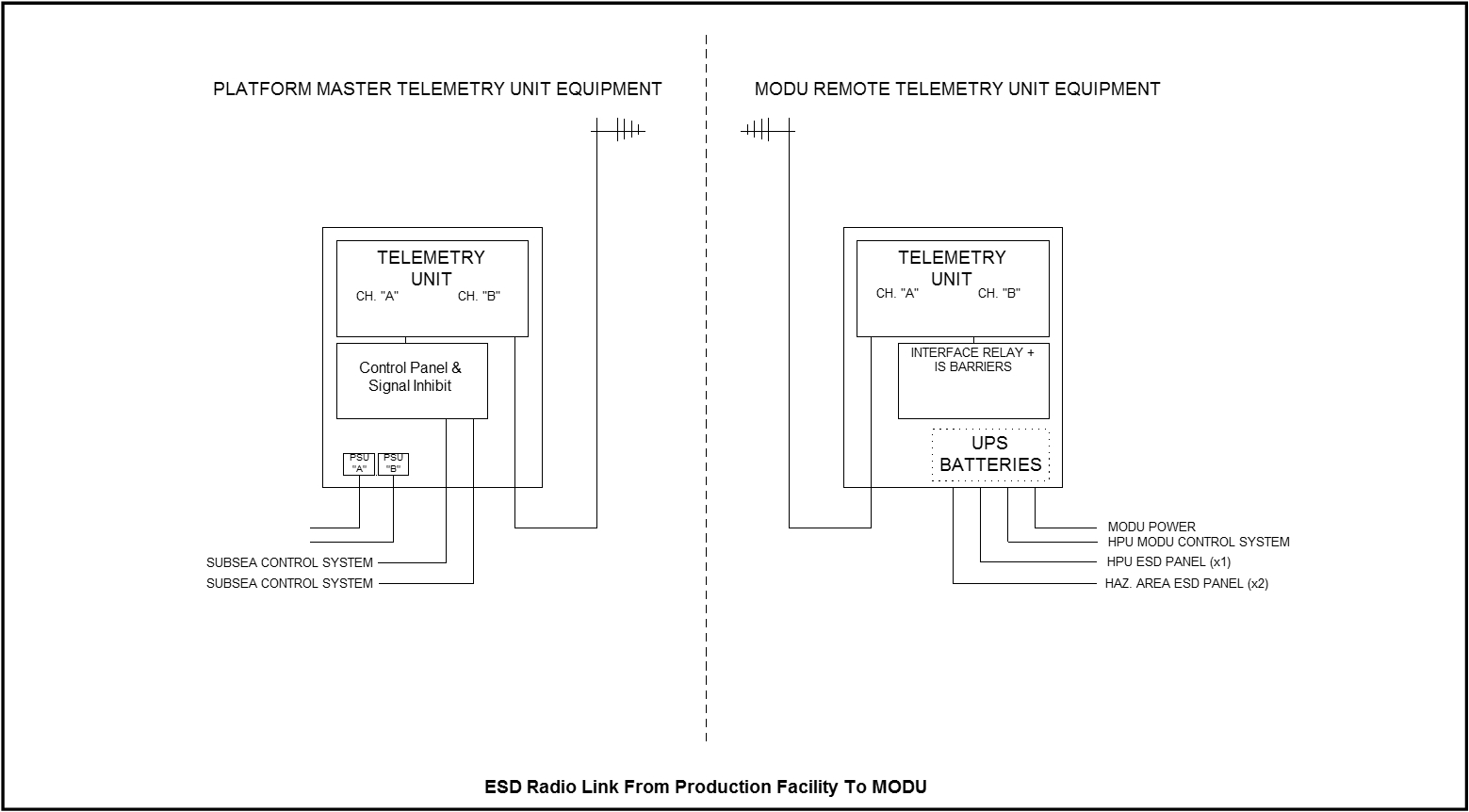
7.4.8 Workover ESD Radio Link
For the larger subsea fields, it is highly likely that Workover will be occurring on one of the wells around a manifold or template at any time, or at least fairly frequently. In this event, an ancillary system is sometime procured along with the subsea control system to provide a radio link between the Workover vessel and MCS. In the event an ESD button on the Workover Rig is pressed (say, if a large object is dropped overboard), a radio signal to the MCS initiates a shutdown of all the Wells in that area.
The radio system itself can be fairly standard in nature, and usually incorporates voice links as well as datalinks, so as to provide extra communication between the CCR and the Workover Rig without tying up the use of one of the UHF channels (usually in short supply, particularly during commissioning) or the ‘Sailor’ VHF sets.
A description of this equipment is outside the scope of this chapter, but the interface with the MCS itself is usually fairly simple, and comprises several digital signals:
MCS to Rig
Rig to MCS
ESD signal
On the Rig, the interface with the Operator is usually several robust hand-held units that can be positioned at the drill floor, Supervisor’s Office, Bridge etc and contain a shrouded pushbutton. Provided the system is ‘enabled’ by the MCS (requires prior arrangement with the Platform OIM/MCS Supervisor), an indicator lamp indicates the system is ‘available’ (i.e. enabled and with radio telemetry operating) and if the button is pressed, a radio signal causes the MCS to shutdown the Field (or local Wells, as per the system design).
The MCS then responds with an ‘acknowledge’ signal, which illuminates another lamp on the Rig handsets. A ‘Test’ mode is usually available whereby the whole link is tested as if in normal operation except that the MCS does not perform the shutdown.
7.4.9 HPU Interface
The MCS will also be connected to the other units of the subsea control system, in this case the HPU, which is always located remotely from the CCR, often on the Cellar Deck or other remote location. It will monitor all aspects of the HPU operation and display the status of the unit in mimic form on the OWS.
In most cases, the MCS has some limited control of the HPU itself, to stop pumps (but not necessarily to start them), to switch between redundant channels and to perform an ESD by venting all subsea pressure.
In some systems, the HPU will be controlled and monitored through the Platform/FPSO DCS and ESD systems, and there is then no interface with the MCS.
The interface in earlier systems is usually ‘discrete’ i.e. each sensor in the HPU is directly connected to a 4-20mA interface in the MCS. Modern systems use a telemetry system that reduces the number of cables required at the expense of added complexity (bearing in mind the usual need for Zone 0 or Zone 1 operation of the HPU).
The HPU itself is a complex unit, and is often operated by a control system in modern units, although this is not essential (see HPU section, Chapter 10, Hydraulic Power Unit (HPU)). Some designs of system use the MCS in the control loop (i.e. when correct subsea pressure is reached, stop the pump) but this requires the MCS to devote a high priority to the HPU subsystem and also means the HPU is no longer a self-contained unit.
Digital messages between the MCS and HPU usually conform to Industry Standard ModBusTM protocols.
7.4.10 EPU Interface
As the EPU (see Chapter 8, Electrical Power Unit (EPU)) is also a sub-assembly of the subsea control system, and is located remotely from the CCR (though usually in a nearby Equipment Room), the MCS has an interface with it to enable displays of key parameters and a degree of control over its operation.
Monitored parameters usually include:
Input Voltage & Current (sometimes ‘frequency’)
Output Voltage and Current (each channel)
Line Insulation Monitoring and/or
Group Alarm
Control capability usually includes:
Remote on/off control
Trip Reset (except Line Insulation Monitor)
The signals between EPU and MCS are usually discrete; it is not usual for a digital telemetry interface to be used.
7.5 Software/Operating System/Displays
7.5.1 Operating System
The Operating System of the MCS is to some extent independent of the Client's functional specification. It will need to be one suitable for the particular computer concerned; typical operating systems are Unix, DOS, or Windows (NT). The choice is usually that of the Supplier's, as it will have built up expertise using a particular Operating System over the years.
The Application Software that runs under the operating System and which controls how the MCS performs and 'looks', is either a proprietary one designed by the Supplier or a commercially-available third-party Process Control programme. The benefit of using the Supplier's proprietary design is that he has complete control over how it operates and can easily and quickly adjust, tailor, or correct errors. Errors in a third-party programme are virtually impossible to have corrected until a new version is issued by the manufacturer; however, such software can present a sophisticated interface to the Operator and has the benefit of (usually) being widely used in Industry and the Operator can usually tailor it (or at least the display) to its own requirements.
Many TOTAL projects which have been supplied by TECHNIPFMC utilise an operating system which is manufactured and supplied by Yokogawa, France. The benefits of using a proven supplier are immense since system and graphic design has already been established and familiarity of client specifications has been demonstrated.
If it is possible, it is always preferable to employ the same supplier to manufacture both DCS (ICSS) and MCS software. This avoids the considerable interface problems associated with combining different software systems.
A typical display has a mimic diagram, valve status information, controls and data. It can be customised to meet the Client’s requirements and to match designs used elsewhere on the Platform or FPSO, to ensure commonality of operation. Modern displays can be animated and use ‘hypertext’-style links to lead to further in-depth information about the system.
In order to avoid the need to mobilise a Supplier representative for small, straightforward changes, the client should ensure at least several areas are available to him for his own use or modification:
The Displays
'Help' systems
ESD sequences
Trends/Historical Data Reporting
7.5.2 Displays
A well-designed display system will allow simple and rapid access to the main operating displays.
Access to more specialised 'maintenance' functions is often also available via the Maintenance Workstation (MWS), but protected by a 'password' system to prevent unauthorised access. These will usually be at several levels of access:
Operator
Supervisor
Maintenance
7.5.3 Operator
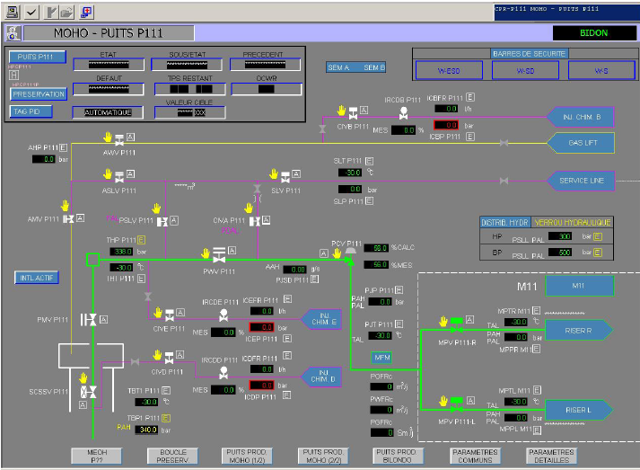
Displays are available to operate the system, although they will be specific to each project, they will typically comprise:
Overview of Subsea System
MCS data including power supplies, communication line status, watchdog status, DCS/ICSS data link status
Data communication failure statistics including all diagnostic data available in the communication protocol
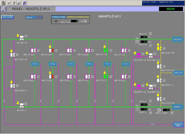
Manifold Distribution Page
Individual Well/Tree pages
HPU data including pressures, reservoir levels, filter status, pump status
EPU (or SPCU) status and data including voltages, currents, LIM’s
Subsea ESD control (Safety Bars) pages
Subsea communication link overview
SCM Monitoring/configuration including hydraulic diagnostics i.e. alarm limits, raw data, raw count ranges, alarm hysteresis, engineering ranges and limits etc
SEM housekeeping diagnostics, details of current status/availability
Process Sensors diagnostics showing parameters for each sensor, including alarm limits, alarm hysteresis, engineering ranges and limits etc
Trends/History (valve data log)
Well Test Control
Choke valves details for parameters settings and process variable selection
The displays will system specific and are usually carefully specified by the Customer to match its existing DCS/ICSS system displays, preferred colour-conventions, method of operating valves etc.
A display 'page' on the OWS will typically be segregated into specific areas, which remain in the same position on every page so that the Operator rapidly becomes familiar with the layout. Modern computer-graphics now allow considerable sophistication in the way information is presented and are often 'Windows TM - based' and considerable care must therefore be taken to avoid overloading the Operator with information or complexity of operation.
The following are examples of typical system graphic displays:
7.5.4 Supervisor
An Operator with Supervisor-level access rights will, in addition to the above functions, be allowed access to the following functions:
Changing Hi/Lo Alarm limits
Cancelling or Pausing an ESD sequence
Placing a Well into ‘Workover’ mode
7.6 Maintenance
An Operator with ‘Maintenance’ level access rights will, in addition to the above, have access to all aspects of the system software. This level of access requires detailed knowledge of the system and is normally only given to maintenance engineers and the Supplier’s representatives.
Typical items that are available under this access level are:
Allocation of Subsea Electronic Module Addresses to individual Wells
Modification of ESD sequences
Altering ‘events’ i.e. conditions which trigger other actions, such as ESD.
Editing of displays/addition of new ones
Modification of ‘Help’ files
Modification of control loops for other related equipment (e.g. HPU control loops)
Direct maintenance of application software programmes and data files
Test utilities, such as disk de-fragmentation, system diagnostics, reloading of SEM software,
7.7 System Functions
This section describes some of the typical operating modes of the MCS in more detail.
7.7.1 Tree Valve Control
In order to operate a subsea valve, it is usual for the system to operate in a ‘check-before-operate’ mode, in which several exchanges of messages take place between the MCS and SEM to ensure that the correct solenoid driver is selected before power is applied to it, thus ensuring the correct valve is actuated. This operation has to be transparent to the Operator, but is usually implemented thus:
On selecting a valve to be operated (via the Tree Mimic or by typing the Tag Number), the MCS will send the ‘check’ subsea command and on satisfactory response will flash the selected valve display. The Operator then has a short time in which to confirm the operation by typing ‘Yes’ or pressing the appropriate button, upon which the ‘operate’ command will be sent.
Whilst the subsea valve is in transit (opening or closing) the display continues to flash (usually in an appropriate colour combination) and on completion of its movement (say, 30 seconds later) will change to steady red (or green as appropriate). It should be noted here that the actual method of confirming the status of a subsea valve depends on the subsea hardware available. There may not be any Valve Position sensors on the valve itself and so the position of the valve can only be ‘inferred’ by virtue of the fact that the SCM has applied pressure to the valve actuator.
During the 30 seconds or so of a valve’s movement, the MCS will usually continue to scan for subsea parameters relating to that valve, as some systems also verify valve status by monitoring the pressure-pulse applied to the actuator and integrate the curve to attempt to determine that the correct volume of fluid has flowed, thus improving the confidence that the valve has not simply stuck. Scanning of other parameters is therefore slowed down during valve operations, although a slower scan rate may still be achieved by interlacing requests for other key parameters or data from other SCMs.
7.7.2 Choke Control
The method of operating a choke depends on its mechanical nature and the nature of its position sensor (see Chapter 20, Subsea Transducers/Sensors).
The most usual type of choke is the ‘stepper’ type, which requires a pulse of pressure to an ‘open’ or ‘close’ piston, which in turn operates a ratchet & pawl to move the choke trim.

In this case, the SCM design to operate it is similar to that for other tree valves. This method of operation is very precise, as one ‘step’ moves the choke trim by a fixed amount; usually some 70-120 steps are required to move from fully closed to fully open.
Other types of choke mechanism do exist, notably the hydraulic motor type which requires a continuous supply of hydraulic fluid to operate a hydraulic motor, and precise position control is less easy as there is always a time delay between reaching the desired position and shutting of the supply of fluid.
A choke position sensor is ‘optional’ for the former mechanism but essential for the latter. These are usually Potentiometers, LVDTs or magnetically-coupled devices on the choke actuator, but as far as the MCS is concerned, it receives a digital value from the SEM indicating position.
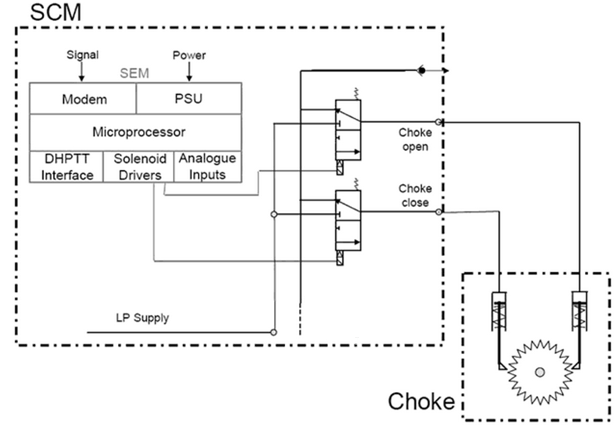
The Operator inputs a desired position of the choke (say, 60% open) and the MCS then computes the number of hydraulic pulses required to reach that position and instructs the SEM accordingly. Often, a ‘single-step’ command is also available, for fine control. To provide these pressure pulses, the SCM has two piloted valves, one for opening the choke and one for closing the choke (see figure below).
The choke control algorithm must be designed to accommodate a number of situations, such as failure of the choke to move (to avoid delaying the rest of the MCS software) or inaccuracy in the computed or measured choke position. It is preferable that the computed position and the measured position are not coupled (closed-loop operation), to avoid ‘hunting’ for an unreachable position, particularly when the choke sensor has an inherent hysteresis in excess of +/- ½ step, which is often the case. An ‘open-loop’ algorithm simply moves the choke the required number of pulses (steps) then stops, leaving the Operator to compare the displayed computed and measured positions.
The algorithm also has to take into account the physical nature of the choke itself, in which the trim remains closed until after a number of ‘open’ pulses and also becomes ‘fully-open’ before the physical final stop is encountered, i.e.:
Number of Steps from ‘fully-closed’ to ‘fully-open’ | |||||
0 | 15 | 16 | 95 | 96 | 120 |
0% Choke Open 100% | |||||
It can be seen from the above that allowing a ‘closed-loop’ operation whereby the MCS continues pulsing the choke until the measured position corresponds with the desired position could lead to uncertain operation at the extremes of choke travel. Similarly, if the choke sensor fails, operation of the choke is then impossible and the system still then has to resort to ‘open-loop’ if any form of control is to be achieved.
Sometimes the MCS is required to display ‘Flowrate’, as calculated from the differential pressure across the choke and the choke position. This is a reasonably straightforward calculation for fluids such as water, but for gas flow it is more complicated. In any event, the software requires calibrations coefficients for the particular choke concerned, in order to apply the necessary polynomial equations. The MCS must therefore store the coefficients for each choke, as supplied by the manufacturer, for use in the equations. Access to these is via ‘Maintenance’ level.
7.7.3 Subsea Sensor Monitoring/Fast Scan
The majority of subsea sensors in a typical subsea system are Pressure and Temperature, as measured by external subsea sensors, which are then connected to the SCM. Other types of sensor include Sand Detectors, Pig Detectors, Choke Position and Down hole Pressure & Temperature. Other sensors within the SCM itself measure the status of the subsea control system hydraulic supplies and status of the electrical systems. In all cases, these result in digital data being made available to the MCS in the uplink data stream.
As stated previously, each sensor is accessed via a ‘status’ request command from the MCS, and therefore it can take some time to access all the sensors in the system. Usually, this is not a problem as a field can usually be ‘scanned’ in 2-3 minutes, which is adequate for normal operations.
Sometimes, however, faster data rates are required, such as during valve movements when attempting to plot the pressure/time curve of the hydraulic supply to the valve, or for Well Test operations (see Para Section 7.7.8, “Well Test Management”) where the Reservoir Engineer is interested in pressure transients just after closing or opening a valve.
If the telemetry system exhibits the scan times mentioned above, it is usually necessary to implement a special ‘fast-scan’ mode for particular sensors, to ensure their data is accessed more frequently, say, once per second (sometimes faster). A special mode is usually available for this where one or more sensors can be put into ‘fast-scan’ mode, which ensures they are accessed more frequently, interposed with normal system scanning requirements.
If the subsea system design cannot offer this, then sometimes the SEM is designed to store a block of ‘fast-scan’ data in memory, for later transmission to the MCS. Careful system design must ensure that this does not prevent normal operation of the system, or overuse of available memory, disk space etc.
7.7.4 Interlocks
In principle, the Operator is allowed to operate any valve he wishes. However, many Clients ask for a degree of protection against inadvertent operations, by implementing various ‘interlocks’ within the MCS software.
Providing a certain condition can be uniquely and precisely defined, the software can then check to ensure no other action is allowed whilst that condition persists, or can only allow an action if a precise set of conditions is met.
For example, an interlock may be set up to prevent an Annulus Crossover valve being opened if the Annulus Master is open. The interlock may merely take the form of an interrogatory question, such as “Annulus Master is open – Continue Yes/No?” to which the Operator can answer ‘Yes’ if required and the action will then be allowed.
The interlock may be a higher level one, whereby only the Supervisor can bypass it, such as opening the Down hole Safety Valve when other Production Valves are open, risking wear on the DHSV.
In an ESD sequence, the Operator is often given the choice whether to close the choke(s) or not (as these are usually closed at the end of the sequence, when all other valves are shut therefore there is no production flow; shutting the choke merely ‘tidies up’ the system in preparation for restarting the wells later, but this operation usually takes a long time and can therefore be avoided if desired).
7.7.5 Alarm Annunciation
All MCS designs offer the expected alarm treatment of sensor readings, viz. HiHi, Hi, Lo, LoLo (HiHi stands for High–High and LoLo for Low-Low) alarms, each of which limits can be individually set by the Supervisor.
Usually, a reading in alarm will cause a flashing symbol on the OWS, plus an audible or Group alarm, a printout on the system printer and a record in the Historical Data Log within the MCS (see Section 7.7.11, “Trends/Historical Data reporting & Data Logging”). The Operator can always cancel the audible alarm, which stops the symbol flashing, but the alarm remains displayed until the alarm condition clears.
Usually, the latest alarms are shown in a fixed screen area on every page. A detailed table of current alarms is available on a dedicated display page, showing current accepted/unaccepted alarms and indicating whether they are Hi/Lo etc. by use of colour or the appropriate symbol (H, L etc.). Once an alarm is accepted and subsequently returns to normal, it is removed from this dedicated page, but a record of its occurrence will be available on the Printer printout and within the Historical Data system.
7.7.6 Workover
The hardware design of the subsea equipment usually allows access by a Workover system, which can take direct control of an individual Well from the Workover Vessel.
The production SCM will be effectively put in to a safe condition and rendered out of service therefore the operator cannot accidentally activate valves whilst in this state.
For safety reasons, Workover operations must always involve the Platform/FPSO Operators, who, upon receiving advice that a well is to be put on Workover, will input this into the MCS after closing all the Tree valves, which in turn will usually ‘grey out’ the Tree valves for that Well and also prevent the Operator from trying to operate that Well. In practice, the Tree valves will be shut when Workover operations have finished, so the display will revert to ‘all closed’ on removing the ‘Workover’ mode. Closing the valves before Workover operations start ensures their status is known, and also that the SCM does not keep pressure on the individual control lines, which would cause the valves to open when the SCM output is reconnected to the Tree.
7.7.7 ESD
The ESD system of a subsea field can be quite complex, due to the number of different modes of shutdown required, as explained in section Section 7.4, “Emergency Shutdown”.
The operation of each of these will be defined in an ‘ESD Cause and Effects’ Chart at the design phase and available in the system operating manual.
Certain ESDs will be activated by incoming contacts from the Platform/FPSO’s ESD system; others will be initiated by the MCS itself, either via an Operator command or in response to out-of-limit parameters.
Each requires subsea commands to be sent to the subsea Tree and manifold Valves in a particular sequence appropriate for the cause.
The sequences themselves can sometimes involve time delays, or allow operator-intervention at particular points depending on the cause and the resultant sequence activated. Many sequences allow the Operator to choose whether to close the Choke or not (as this is usually a time consuming operation).
A well-designed MCS system will allow access via ergonomic editor software such that the sequences can be modified if necessary or time-delays changed, etc.
A typical simple shutdown sequence could be:
Close all Production Wing Valves (this will stop production flow)
Close all Production Master Valves
Close all Annulus Valves
Close Down hole Safety Valves (Operator choice)
Close all Chokes (Operator choice)
The software also must take into account the desired action, should any of the issued commands fail to operate (usually, this will be to initiate a hydraulic shutdown via the HPU i.e. ESD0) and must also take into account a system in which not all the Wells are yet installed. Different sequences will be required for Process shutdowns of Water-Injection Wells, and for Production Wells that must have Chemical Injection before fully closing them down.
7.7.8 Well Test Management
Reservoir management usually requires various forms of Well test procedures to be carried out, usually routing product into a Test Separator, and monitoring subsea pressures immediately after closing or opening Production valves (well shut-in, well start up tests) from which Reservoir Engineers can deduce the characteristics of the reservoir.
To achieve this, a sequence of valve operations plus associated ‘fast-scanning’ of various pressures and temperatures is usually required. This can be a manual operation performed by the Operators, or if the sequences or necessary control actions are too complex, can be automated, such that the operator merely has to select, say, “Well Shut-in test, Well 1”, and all the necessary valve commands and fast-scan actions are carried out automatically
Usually, the resulting data will be made available to third-party analysis software, by means of downloading the data onto USB key or HDD, in an established/agreed format.
In some systems, a separate Test Flowline exists and by operating the required valves, flow can be routed from one particular well into the Test Separator. Again, this action can be made automatic if required, although Operators usually prefer to perform the operations themselves.
The software can be made to ‘detect' if a well is placed on test, and a warning indication set on the relevant OWS screen(s). In this case, an incoming “Test Separator ESD” signal is then ‘routed’ such that only the particular well on test is shutdown, rather than all other producing wells.
Most of recent deepwater developments don't have separate test flowline as subsea MPFMs are used in place.
7.7.9 Hydrate Region Warning
Certain Fields contain the type of crude which has a tendency to form hydrates at particular temperatures & pressures conditions (hydrates are forming at low temperature and high pressure conditions), and the Operators must always be vigilant that these are avoided, or are at least prepared for the eventuality by previously injecting chemicals like MeOH, LDHI or MEG (MEG mainly used for gas field as MEG can be recycled in order to be reused).
The MCS can be programmed to continually monitor the pressure and temperature of the crude, and activate an alarm if the values fall within the hydrate envelope.
In principle, the MCS could also be programmed to perform valve operations on activation of this alarm, such as to inject chemicals or to alter choke positions to bring the pressure out of the hydrate region, but it is more usual that these actions are left to the Operators to perform.
7.7.10 Reports
A MCS is usually equipped with a variety of pre-defined Reports, which can be selected by the Operator as required, or can be made to print automatically, say, every 24 hours.
Ideally, the MCS should be equipped with Operator-definable Reports, in which the Operator can select the parameters to be printed, perform operators on them (such as ‘total’) and design the format, but this does require quite a sophisticated editing program.
Alternatively, selected data can usually be output from the Historical Data System (see 9.7.11) onto a USB stick or HDD or similar, for later processing via third-party software. Usually the regular ‘Daily Reports’ are produced by the higher-level Platform/FPSO SCADA system, which has access to topsides production and export data, so Reports from an MCS are not used very often.
7.7.11 Trends/Historical Data reporting & Data Logging
Being a computerised system, an MCS is able to store all the data received from subsea, plus any ‘events’ (such as alarms or Operator commands) on its hard disk drive, for a period of time.
Most MCS software, whether third-party or in-house design, provide some form of graphical data-retrieval system that enables the operator to view previous data, usually in the form of a chart-display over the period selected.
Display space limitations usually restrict the number of parameters that can be viewed at the same time to around 3-6. Selecting more parameters for display can often occupy the MCS processor and disc system to excessive tasking and can slow other operations.
A typical graphical display of historical information is as follows:
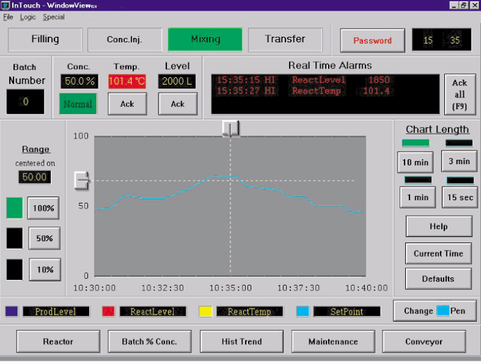
The Operator can select the start and stop date and time for the selected parameter – the MCS will then retrieve the data from its hard disc and display it graphically, or a tabular display is often available.
There are physical limitations to the amount of data that can be stored by any system, and certain compromises may have to be accepted at the design phase in order to optimise the system design between a practicable system capacity and the Clients’ requirements for data storage.
In practice, an Operator is likely to need very detailed information stored for a short time (e.g. when performing Well Tests) but less detailed information for long-term storage. It is also very useful to be able to refer back over several months of data to find out, say, when a sensor failed (and try to relate it to some other event such as Workover at the time), or what caused a pressure to rise etc, in which case all ‘relevant’ events, such as Operator actions, need to be retained, but ‘irrelevant’ event, such as those inevitably resulting from major event, are candidates for being removed from the database (e.g. hundreds of alarms can result from the one major event of switching off the EPU).
It is not particularly easy to adequately define such an ‘alarm hierarchy’ and the storage limitations of the MCS mean that printouts or data-storage of the database must be performed sooner rather than later when an event needs to be analysed.
The same system may be used to display the value of selected parameters in ‘real-time’, thus providing ‘Trend’ information.
7.7.12 Tag Numbering
Any subsea development will use a system of Tag Numbering, developed by the Client or its major contractor, which is used throughout the FPSO (or Platform) and subsea system as a standard nomenclature for defining valves and sensors.
Very often, a contract is placed for the subsea control system before this standard Nomenclature system is in place, and the system begins design using the Supplier’s own nomenclature, or internal computer reference numbers for each data point.
The Tag Numbers then have to be retrospectively modified by the controls Supplier, which is a complicated task, as it may involve a complete rebuild of the MCS database, and the Supplier will usually claim a Variation for this work.
A preferable solution is the ability of the MCS to use client-definable/re-definable Tag Numbers via a relational database lookup system, such that arbitrary numbers can be used to begin with, then easily replaced with the final versions, the MCS ensuring that all occurrences of that Tag Number being automatically updated to reflect, display, and respond to, the new value.
7.7.13 Operator-Specific Requirements
The MCS is sometimes configured to provide for operator-specific requirements, such as down hole data-logging and pseudo-leak detection.
Down hole data-logging
Reservoir engineers may wish to analyse down hole pressure and temperature data, particularly during shutdowns. Data logging to disk may be initiated manually or automatically, sampling rates may also be set manually or automatically to suit the particular application.
Pseudo-leak detection
Pressure-sensors can be selected from which rate of change of pressure derivatives can be set to initiate shut-in of wells when a set-point is exceeded.


