
29 Alternative Control Systems
29.1 Introduction
The primary factors affecting the control system design are the Field architecture and Offset Distances (refer to section 7), and for most cases, an electro-hydraulic Multiplexed control system is suitable.
However, the Offset Distance from the subsea production equipment to the host facility FPSO or the onshore facility may dictate that other solutions are considered. The installed cost of a long or complex composite electro-hydraulic umbilical carrying power and signal cables, hoses for low pressure and high pressure hydraulic systems, and the additional chemical injection hose requirement for services such as corrosion inhibitor, scale inhibitor, wax inhibitor, or methanol for start-up, can significantly reduce the overall field economics.
There are two options for eliminating long length umbilicals in this situation. They are:
buoy based systems where all of the control requirements are located at the surface.
autonomous subsea systems where all of the control requirements are located on the seabed.
Another option is to limit umbilical complexity and size in order to reduce associated CAPEX by removing chemical lines and/or hydraulic fluid lines from umbilical by respectively installing
A subsea chemical injection unit (TOTAL Concept named Subsea Chemical Storage and Injection (SCS&I) system
Installing a subsea HPU (Innova product) or replacing valves (SCSSV included) by e-valves (Innova e-actuator, TechnipFMC G3i e-actuator and e-spring actuator, etc.)
29.2 Buoy Based Control Systems
The buoy concept has been around for many years. The concept is that all of the control requirements are installed onto a buoy which is moored above the subsea facilities and which carries all of the control requirements. An umbilical from the buoy to the seabed facilities transports all of the required functions.
The original concepts for such buoys proposed low-cost flat-bed barge designs, but later concepts and the buoys that have since been installed have been substantial ‘spar’ type designs.
The ‘spars’ have a large draft below their surface to provide stability. These are unmanned facilities but there is a requirement for warning lamps and for radar reflectors for positioning requirements.
The buoy has to carry the hydraulic power unit (HPU) and Electrical Power Unit (EPU) for the subsea control system, and chemical injection pumps and reservoirs for the injection requirements. Control has to be by a dual high-integrity, secure radio link.
Electrical Switchgear is required for motor starters, and for lighting circuits and safety requirements. There is also a requirement for power generation. A dual system is required for redundancy and batteries are required for back up.
Storage facilities are required for fluids. Tanks are required for hydraulic fluid, injection chemicals, and diesel for the power generation. As these are unmanned facilities, the size of the storage tanks may well become substantial. The designer has to make a case for the periods between bunkering of fluids. If the storage amounts are minimised, it is essential that all-year-round supply boat access is available in order to prevent unplanned shutdowns.
One spar buoy design has such a deep draft that elevators are required to transport personnel and equipment between decks. The fabrication of such buoys is done in such a way that equipment skids are installed onto the decks during fabrication. It is essential, however, that major items, such as pumps, can be retrieved and replaced if necessary, so modular design of equipment is required.
The buoy has to be secured to the seabed using anchors or piles, or a combination of both. There has to be a means of connecting and disconnecting the control umbilical.
A major issue is personnel safety. Maintenance personnel need to be able to safely get on and off the buoy for maintenance and bunkering of utility fluids.
There is a need for air-handling systems, fire-detection systems and fire dampers, emergency access ways, etc. In addition, there is a need for food and fresh water, and temporary accommodation in case it is not possible to get off the buoy due to bad weather.

The East Spar field is 63 km southwest of Varanus Island, off the northwest coast of Australia in 95 m of water.
29.3 Autonomous Subsea Systems
29.3.1 Introduction
To dispense with the subsea umbilical there is a requirement for electrical supply, hydraulic power supplies (requirement for hydraulic power supplies can be overcome in case of full electric system, subsea structures equipped with E-valves), solenoid valves, control and monitoring, and acoustic communications – all subsea. These are the elements of the autonomous control system.
Whilst electricity can be stored in batteries (and some battery storage is always necessary), there is the requirement for subsea power generation. The batteries need to be sized to withstand production and planned annual shutdown requirements, and to be able to supply a peak load for start-up requirements. Battery technology is continually improving and an optimum battery can be selected at the time of use.
The criteria for battery selection are minimum gas production, minimum maintenance, reliable battery performance, final voltage as high as possible, and capability for partial charge and discharge.
29.3.2 Power Generation
A turbo-generator could be used for a dry gas service using a bypass loop from the main production flowline, or from a gas lift pipeline if used. As with all rotating equipment, there is a reliability consideration in that the sealed bearings would have to meet the equipment design life without additional lubrication, and that the electrics would need to be segregated from the gas source. The rotating speed must be governed to limit the axial thrust on the bearings.
Where produced fluids such as oil, water, and gas condensate are to be considered, the reliability of the turbo-generator has to be questioned. An alternative is thermo-electric power generation.
Thermo-electric power generation is based on the ‘Seebeck Effect’. When the junctions of two dissimilar metals (semi-conductors) are maintained at different temperatures, a potential difference is created which produces a flow of electrical current in a circuit. (In submarines the reverse ‘Peltier Effect’ is utilised to develop silent cooling systems).
The design of such a device needs to consider the best interface material between the thermo-electric elements and the hot and cold plates, and take into account the seawater conditions. The selection has to be compatible with seawater for long term use and reliability. The reliability over the turbo-generator is greatly enhanced, as there are no moving parts.
The thermo-electric elements are arranged externally around a pipe spool, and are therefore non-intrusive. The elements must be sized to provide an output to meet the design specification. The heat flux from the pipe spool source to the cold seawater can be optimised by using cooling fins on the external plate and increasing the exposed surface area. The spool can also be installed in a vertical plane to promote convection currents. A copper alloy cover can be used to enhance the thermal transfer as well as inhibiting marine growth.
29.3.3 Subsea Control System
The control system is packaged into a module to include the Hydraulic Power Unit (HPU), Power Conditioner System, Motor Control System, Subsea Electronics Module (SEM), and solenoid control valves.
The HPU provides the hydraulic fluid power to the valve control system. It includes the reservoir, pumps, motors, accumulators, and filters in a dual configuration. Well control usually requires Low Pressure and High Pressure systems, but HP can be generated from LP using intensifiers. As the reservoir cannot be replenished without intervention, closed hydraulic systems must be used for this application.
The Power Conditioner System provides the interfaces between the generated electrical power, the electronics, and the batteries. It provides the power to the electronics and maintains the battery charge at the correct level.
The Motor Control System provides the interface between the hydraulic pump motors and the power source, and provides the motor control.
The SEM contains the electronics for communicating with the surface, controlling and monitoring, and data collection. The units need to have some autonomy and to be able to initiate a shutdown should the acoustics not be communicating correctly. Therefore the SEM will be control board controlled.
The solenoid control valves are electrically energised directional control valves, contained within the SCM for functioning the Xmas tree valves.
29.3.4 Hydro-Acoustic Telemetry System
Temperature, pressure and salinity are all major factors in control of underwater acoustic propagation. The temperature is the most important in the UK North Sea areas, as seasonal variations in the temperature/depth profile are considerable, with a corresponding impact on the sound velocity/depth profile.
The degree of ray bending at any time is determined by the current temperature/depth profile and has a major impact on the acoustic link between any two fixed locations as the horizontal separation increases. With seasonal variations this link can exhibit the following characteristics:
A direct path
No direct path, but one or more bounces via the surface to the seabed
Zero signal transfer
In addition to the variability of the main path, there are multipath signals that arrive with variable delays, amplitude and phase, causing interference with the main signal.
For a permanent installation between a wellhead and a platform, the link must be capable of operating in all conditions. This is achieved by having one or more transducers deployed at different depths on the platform jacket structure.
Data rates are fairly slow and 300 baud is typical, and can be lower in difficult conditions. For this reason, the control system itself has to have autonomy for emergency shutdown situations.
Communication distances of 10km are practically achieved using low frequency transmission, typically in the 15-17 KHz range. Telemetry system designs of between 20 km and 30 km are claimed.

29.3.5 HAPAC
The principles of the autonomous control system have been studied and proto-type tested by TOTAL in the Hunter Autonomous Power Generation and Acoustic Control Project (HAPAC).
The Thermo-Electric Power Generator (THEG) was built using Bismuth Telluride p-type and Bismuth Telluride n-type as the two dissimilar semiconducting metals which can operate at up to 200ºC. Using THEGS with 6 rows in parallel and 56 plates in series, laid in a hexagonal configuration around the pipe spool, a maximum power output of 130 Watt was achieved with an internal water temperature of 120ºC and external water temperature of 4ºC.
The subsea control system used had been developed by Kvaerner FSSL for the SPARCS Project, and was updated for use on HAPAC. The system was modified to be used with Simrad and Sonardyne acoustic systems. A single pressure 207 barg hydraulic supply was used for the test.
The target acoustic range for the test was 10km subject to acoustic propagation conditions and platform noise levels. A high transmission level of 214db (reference to 1 micro pascal pressure) was selected.
An operating frequency of 15-18 kHz was selected to prevent interference with other commonly used acoustic systems. It was also a good compromise between low attenuation for operation to 10km or greater and the ability to produce directional transducer arrays that were not too large.
A three element transducer array was used to provide a ±7.5º vertical beam with a broader horizontal beam of ±30º to compensate for the easier alignment of the arrays in the vertical plane relative to the horizontal plane when installed.
The transmitted source level was adjustable in 6db increments from 196db to 214db, and the data rate from 10 baud to 300 baud to enable optimum performance to be achieved, and to cope with seasonal variations in the propagation conditions.
An acoustic propagation study was conducted using ray path trace analysis for sound velocity/depth profile data over a range of 5.2km and in a water depth of 130m. Ray paths were computed for each month over a 12 month period to establish the seasonal variation.
The results of the analysis are summarised below:
Over the summer months, there is always a direct path from the platform to the subsea well site.
As the summer progresses, a thermocline develops which gets steadily deeper and thereby prevents acoustic communication at transducer depths shallower than 100m in September.
In winter there is no direct path but there is always a path with a single bounce from the surface.
The optimum depth for the platform transducer was 100m.
The Total Exploration Production HAPAC Final Technical Report was issued in April 1999.
29.4 Alternative Technology
29.4.1 Introduction
This section discusses the application of recent technology to subsea control systems, whereby a system may be improved, or made more cheaply, by benefiting from advances in compatible techniques.
29.4.2 Fibre Optics
Subsea control systems have traditionally used slow but robust telemetry systems for system communications, operating over copper wire cores in umbilicals. Communications at 1200 baud using half-duplex telemetry was prevalent. This was acceptable for polling of control modules and the occasional valve command, but it is not acceptable for large amounts of data. In addition, it can take several minutes to do a total system scan and therefore the data retrieved is not available in real time.
This may have been adequate in the late ‘70s when a state of the art modem was not much faster. However, the advance in telecommunications and the Internet has left these telemetry systems outmoded.
There is a need for real-time telemetry in production systems, and in particular when High Integrity Pipeline Protection Systems (HIPPS) are required by the design. In addition, the requirement of additional monitoring for field diagnostics and reservoir data has exhibited the need for a step change in communication technology for certain applications.
Fibre optic technology
Fibre optic cables are capable of transmitting a large amount of data at a very high rate. The need for deeper water applications and the move to subsea processing has made the use of fibre-optic communication systems a serious consideration.
There are two types of Fibres: Multimode and Singlemode, and the advantages and disadvantages are as follows:
Multimode
Advantages:
Large core tolerates connector misalignment
Low cost transmitters - LED technology, short wavelengths
Disadvantages:
High attenuation – 3dB/km @850nm, 1.5dB/km @1300nm
‘Low’ bandwidth – 500MHz.km
Singlemode
Advantages
High bandwidth >2000MHz.km
Low attenuation – 0.5dB/km @1310nm, 0.3dB/km @ 1550nm
Disadvantages
Small core sensitive to connector misalignment
More expensive transmitters – Laser technology, long wavelengths
In both Singlemode and Multimode fibre the attenuation is caused by light travelling down the fibre is scattered out of the fibre and absorbed by the fibre.
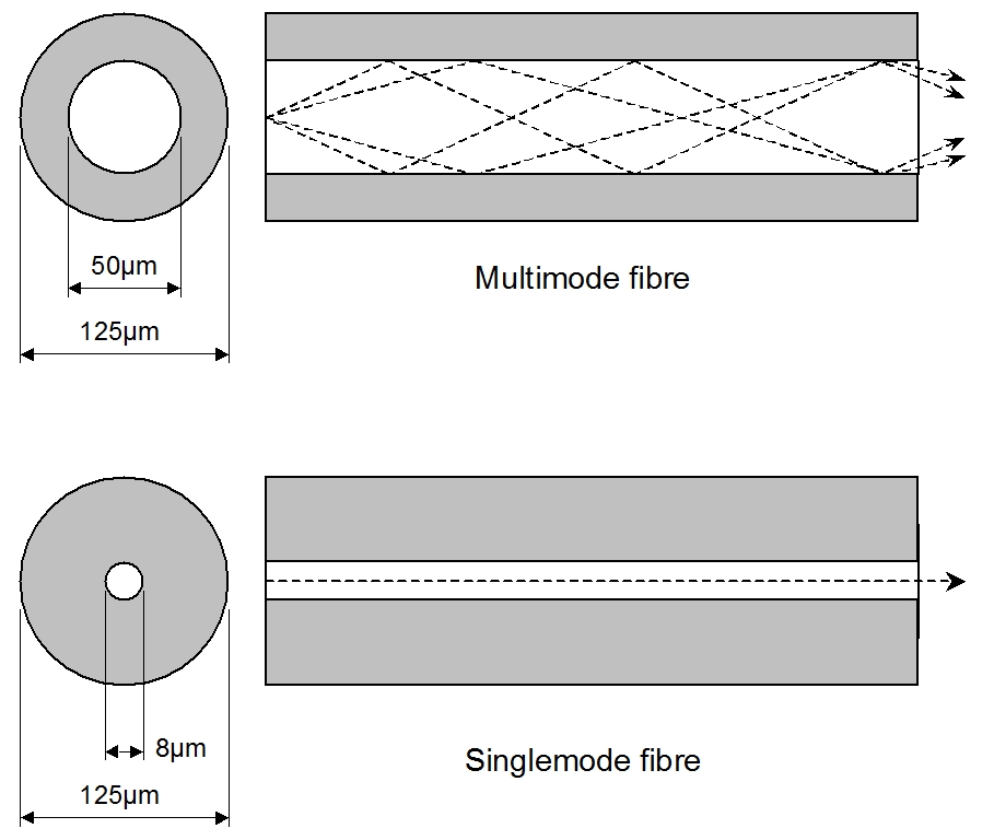
The high communications bandwidth on Singlemode fibre supports increased sensing and control facilities. The bandwidth is limited by the transmission system and not by the fibres themselves or the connectors. Modems are readily available developed and used in the telecoms industry and wet-mateable fibre-optic connectors have been in use since around 1997 as a controlled-environment type connector.
The connector brings together two shaped and polished fibre ends with a misalignment of less than two microns to achieve a connector loss of less than 0.5dB. The misalignment may be axial, angular or longitudinal causing loss due to light being reflected by the end of the fibre and scattered as it leaves the fibre. This reduces the amount of light entering the mating fibre.
The increased bandwidth can be achieved with a reduction in size from a single electrical-conductor pair, and hence a reduction in umbilical cross-sectional area, and hence umbilical cost.
The move towards subsea processing will require different types of electrical equipment on the seabed. For example, for long offsets, there may be a requirement for high voltage cabling. It would not generally be cost effective or economic to install a separate power and communications cables, and hence signals running over long distances next to high voltage power conductors need to be noise tolerant. Optical fibre offers complete immunity from signal corruption caused by exposure to electromagnetic interference (EMI).
Fibre optics can also provide secure and uncorrupted communications. Where a subsea field might be tied back to another Operator’s host facilities, digitally encrypted signals can be used to keep data secure.
This can be of particular interest when using a network such as the FibreWeb™ network in the Gulf of Mexico, where fibre optic cable routes along the seabed from near Houston to near New Orleans, routing around several rigs and platforms. The fibre cable is mainly for voice communications as an alternative to radio or satellite, but the opportunity to tie-back and control a subsea development or the possibility of 100 sensors in line on any one fibre provides many opportunities for technology development.
Field acreage may have been previously drilled and reserves proven that may not be economic to produce as a stand-alone development. These assets may be revisited as the technology develops and the support infrastructure develops. Fibre optic based systems offer the ability to communicate over distances of 100-200km with no subsea signal repeaters.
In addition to the above, fibre optics have provided an economic and reliable solution for monitoring downhole pressure and temperature. Temperatures in excess of 1000ºC can be measured which exceeds the survivable performance of all electronic gauge systems.
Fibre optic architecture options
The additional fibre optic components, subsea distribution and termination locations for typical subsea architectures are as follows:
Umbilicals: Each fibre optic tube can be populated with multiples of 6 fibres. On a project by project case the number of fibres could be reliably increased to 36 without noticeable impact to price. Caution is highlighted though as increased numbers do add complexity to termination and distribution options.
Umbilical Breakouts: Breakouts at each UTA and manifold are considered. There are a number of design options for distribution within the umbilical termination units. Use of dry-mate connections provide design flexibility and assembly benefits, and are the favoured solution by some suppliers. However, fusion splicing to the pigtails of a bulkhead wet-mate connector is a relatively straight forward and field proven process and would be cost effective for most architectures. From a reliability perspective it is desirable to minimize all types of connections wherever possible.
Subsea Router Module (SRM): There are a number of manufacturers today offering dedicated data acquisition subsea modules that are designed to exist in conjunction with traditional subsea control modules.
TechnipFMC, Aker Solutions, OneSubsea, Weatherford have multiple units in operation today and all offer fibre optic modem connectivity.
Most of the recent modules are based on open architecture functionality (see below).
Connectors: The two connector suppliers with most field proven product experience are ODI and Seacon. ODI have the largest market share to date and appear as the supplier of choice for most of the wellhead control companies.
Subsea Fibre Optic Distribution
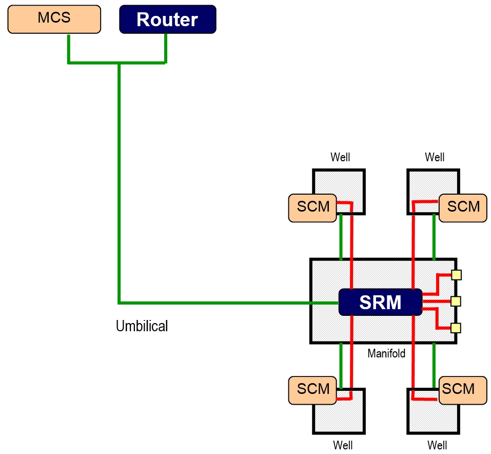
The basic philosophy is to position a Subsea Router Module (SRM) at each manifold or equivalent distribution location. The fibre optic cores are terminated at SRM and onward communication to Subsea Control Modules (SCMs) and all other instrumentation is established by electrical means. This minimizes fibre optic connections and increases the flexibility of a local area network by utilizing standard subsea jumpers. Expansion connections are recommended to provide future extensions to the network and alternative routing for production and process instrumentation.
Note that such Fiber Optic Distribution has been implemented on TOTAL deepwater developments like CLOV, Moho Nord or KAOMBO where each Manifold is fitted with two SRM (A & B) for redundancy and one Manifold Control Module with inside two SEMs.
In the case that individual wells are connected via in-line Tee’s the fibre optic connections are recommended to be routed to the X-Tree. This is achieved with breakout connections at the in-line Tee and fibre optic jumpers to the X-Tree. In this case the benefit of a dedicated SRM is greatly reduced and unless there is some specific instrumentation requirement such as DTS, it is likely that the subsea router functionality would be integrated into the SCM. This option increases fibre optic connections, reduces flexibility and expansion options and increases complexity of the SCM. All the technology for this configuration exists and is deployed on projects (Brenda, Columba-E).
Control Philosophy
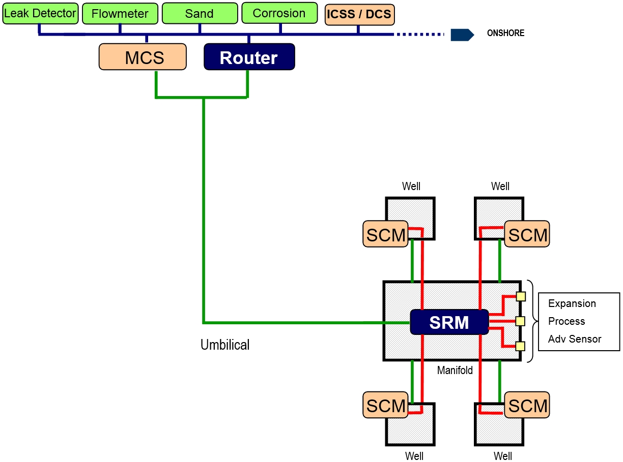
The diagram above considers the recommended manifold configuration and introduces the additional topside infrastructure. In this configuration there are two methods of control and monitoring available that can be separated and operated independently or integrated in a dual redundant configuration. Commands can be transmitted to the SCMs from the MCS directly via the power cores in exactly the same manner that subsea systems are controlled today. This is a low bandwidth system that loses all the benefits discussed in this section but does provide a fall-back position that could permit operation in a degraded mode. Alternatively the MCS can communicate with the SCMs via the topside network router and the SRM. This introduces the high speed network and provides the potential to utilize all the functionality.
There are many options and permutations available within this configuration to control and monitor non SCM functions. The surface acquisition unit for the Flowmeter for example could communicate with the MCS via the topside network to access its data or initiate commands as is common practice today. Alternatively it could communicate directly with the subsea flowmeter via the topside router and the SRM. The implementation is driven only by the choice of connection subsea – it is either plugged into the SCM or the SRM (it may of course be possible to plug it into both units). The diagram below shows this architecture from a functional perspective.
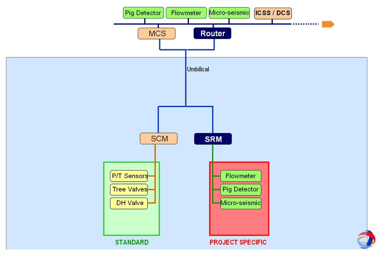
The above figure shows a split of X-Tree control associated sensors and more project specific process sensors. It is recommended that sensors related to the integrity or control of the X-Tree remain connected directly to the SCM. However, the creation of an expandable and flexible data network platform for all other instrumentation should be seriously considered on a project by project basis. In this way we remove additional loading on the X-Tree functionality, introduce almost unlimited data access and provide easy expansion throughout the project execution or future operations.
This enables the final decision for advanced instrumentation to be defined much later in the project cycle when its true requirements are better understood. It also permits the SCMs to be more generic across a project even when different module locations have significantly different monitoring requirements. Today it is usual to have at least three or four different module types (manifold, production well, water injection well, subsea router module).


