
5 Flowline System Architecture
5.1 General
The subsea layout (i.e. location plan of the subsea structures, including wells, and the route of the different flowlines) is the result of a complex optimisation process between numerous requirements including:
The well distribution over the field for an efficient drainage of the reserves
Drilling considerations (e.g. safe handling zones to minimise dropped object risks)
Water and gas injection wells adequate locations for re-pressurisation of the reservoirs
Minimisation of the flowline total length for cost savings
Flow assurance considerations.
The flow assurance issues are critical for the definition of the flowline system. They include various considerations and requirements which impact the architecture and design of the lines, as follows:
Liquid and gas flow requirements, including pressure and temperature at the arrival on the platform, operating and shut-in pressures, production rates, etc.
Active lifting requirements (e.g. gas lift, see Chapter 6, Subsea Processing and Active Lifting)
Hydrate management plan
The flow and hydrate management strongly impact the flowline system design, e.g. by requiring dual flowlines arranged in pigging loops or by restraining the distance over which the fluids can be transported.
In deepwater fields, seabed temperatures are very low, e.g. at around 4˚C. These temperatures require protecting the lines to avoid hydrates (which forms under high pressure and low temperature) or wax formation, particularly during shutdown and restart situations. These solids can build up and result in a plugged flowline, requiring production shut down while taking remedial actions.
To avoid these flow assurance issues, several measures can be adopted. The widely used solution is to keep temperature level in the flowlines above the hydrate appearance temperature, either by using a thermal insulation (e.g. wet coating, PIP) or heating methods (electrical heating techniques, hot fluid circulation). Refer to for further details on these technologies. Another possibility is the injection of hydrate inhibitors (methanol, glycol) in the lines (e.g. in combination with an insulation coating).
For the same purpose, the subsea flowlines are commonly installed as dual flowlines to form a loop that enables the implementation of several preventing or remedial activities: flowline depressurisation, replacement of the flowline content with inert fluid (dead oil), warming up of the flowline (hot dead oil), and round-trip pigging to clean off pipe-wall wax deposits. This widely used 'looped' configuration is detailed in the following Section Section 5.2, “Production Loop”.
However, the development of different technologies (e.g. subsea processing) allows to overcome the need for such an expensive dual configuration and allow the use of single flowline. These architectures are presented in Section Section 5.3, “Single Production Flowline”.
![[Tip]](tip.png) | Tip Click these links below for access to 3D resources: |
5.2 Production Loop
5.2.1 The 'Daisy Chain' Architecture
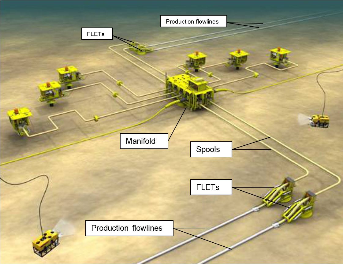
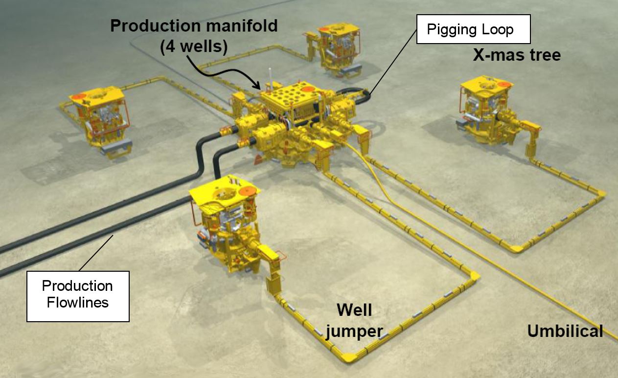
The most typical architecture for a deepwater subsea development features production flowlines and manifolds arranged in a 'daisy chain' configuration. This consists in having segments of dual production flowlines linking every manifolds of the same loop with a pigging loop installed on the last manifold to allow round trip pinging. See the following Figure 5.2, “Dalia 'Daisy Chain' configuration – typical mid-manifold arrangement detail” and Figure 5.3, “Girassol and Rosa 'Daisy Chain' configuration – end-manifold arrangement detail” depicting typical 'daisy chain' arrangement with drill centres in cluster configuration and production flowline loop (TOTAL Dalia, Girassol and Rosa projects). The Figure 5.1, “Total's Pazflor development featuring 'daisy chain' for the Oligocene reservoirs” bellow shows the TOTAL Pazflor development scheme, which features a conventional 'daisy chain' configuration for the Oligocene reservoirs while a subsea processing / single flowline configuration is adopted for the Miocene reservoirs see also Section Section 5.3.4, “Subsea Processing”).
This architecture has the following advantages:
Full ‘piggability’ of the system, including the flowlines, manifolds and related spools.
Depending on the manifold location in the field, it is possible to radically modify the direction of the flowline lay at the manifolds (thank to the discontinuity).
The main disadvantage is related to the installation, as FLETs lay-down and initiation are required for each line at each manifold location, i.e. increasing the subsea structure numbers and the subsea operations to be performed.
5.2.2 Offline Alternative Configuration
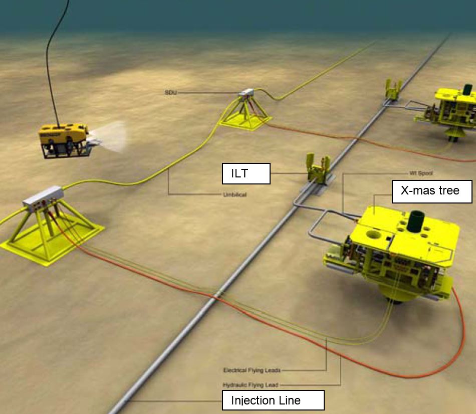
The ‘Offline’ configuration consists in locating the manifolds out of the pigging loop. For that purpose, the production flowlines are equipped with in-line tees (ILT), which permit the manifolds to be tied onto the flowlines by means of tie-in spools. Unlike the standard 'daisy chain' configuration, the round trip pigging does not pass through the manifolds nor their spools but only through the flowlines.
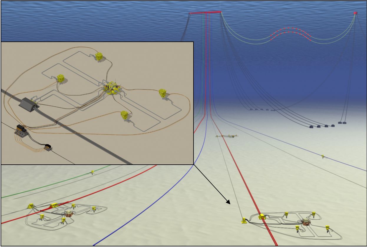
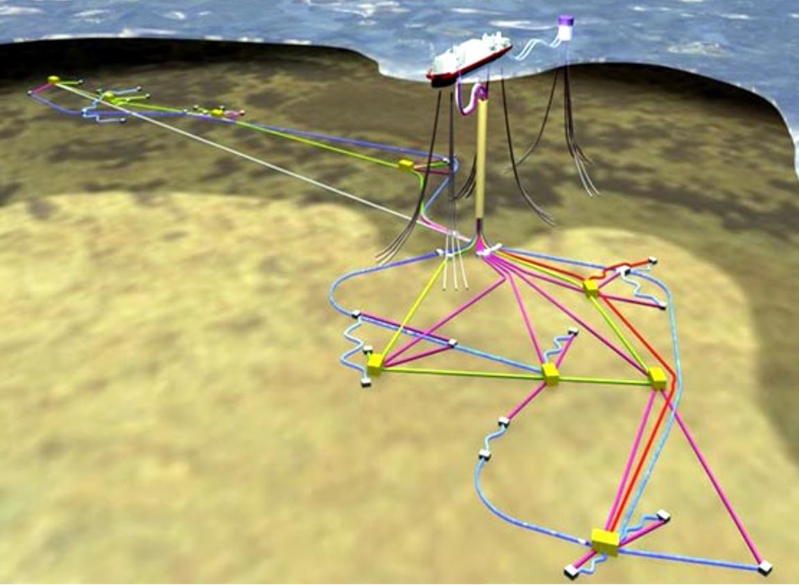
The Figure 5.4, “Field development featuring offline arrangement (artistic view)” below is an artistic view of a field development featuring an FPSO connected to an export buoy through two offloading lines in 'wave' configuration, injection flowlines (green and blue lines) fitted with ILT for well connection and production loops (red lines) / manifolds in an offline configuration.
The main advantages of such a configuration are as follows:
Continuous pipe-lay operation for the flowline installation
Two connections are freed on each manifold for two additional wells, if required
Lighter manifold structure, e.g. 5D bends and ‘piggable’ header valves not required.
Manifold can be retrieved without shutting in the production flow-loop.
Tie-in spools are not pigged, so 5D bends are not required – smaller spool dimensions
The main related disadvantages are the followings:
Larger pipe expansion due to continuous flowline, to be mitigated within tie-in spools.
Manifolds cannot be ‘pigged’ and require MeOH injection for hydrate prevention strategy.
5.3 Single Production Flowline
5.3.1 General
While the dual 'looped' flowline configuration provides flexibility for several activities, it does however come with the penalty of doubling the cost of the system.
Different method can be implemented to overcome this issue, such as the use of a single production flowline to connect the manifold but returning to the floater to form a 'daisy chain' configuration (e.g. Greater Plutonio field, Section Section 5.3.2, “'Daisy Chain' Single Flowline”), the use of a big diameter service line (in combination with a single production flowline) to be used as the second branch of the pigging loop (Section Section 5.3.2, “'Daisy Chain' Single Flowline”), or the development of subsea technologies which allow to avoid the requirement for regular pigging (Section Section 5.3.4, “Subsea Processing” and Section 5.3.5, “Cold Flow”)
However, such single production flowline in place of a looped system do not allow performing some specific operations. This includes well switching (testing) between either flowlines and the flexibility to shut-in one flowline whilst continuing to produce through the other, i.e. the ability of the system to accommodate varying production profiles over the field life.
5.3.2 'Daisy Chain' Single Flowline
This configuration consists in performing a loop with a single flowline which is connected to the floater at its two extremities, thus allowing pigging operations. This can be performed either by the production flowline or by a combination of production flowline / service line.
The configuration featuring a production "looped" with service line of similar diameter provides a pseudo round trip pigging capability, thereby substituting the function of a full production loop. In case of similar but not equal diameters, the use of pigs capable of accepting such variations (e.g. foam pigs) is required. It could be envisaged to base the pigging of the different lines on subsea pig launching / receiver units for single trips, but at the cost of more complicated procedures and operations.
Such configuration has been adopted for the BP's Greater Plutonio project (Angola, WOA).
The development is based on six fields, which are spread over a wide area (35km from Platina to Cobalto) with water depth varying from 1,200m to 1,500m. It is based on subsea wells tied back to a single spread moored FPSO facility with a storage capacity of 2 million bbl. The produced gas is re-injected (first development phase) and the production is exported through an offloading buoy.
The development includes a 'daisy chain' production flowline (i.e. a single production line looping from the FPSO, through the manifolds of the field South part and returning to the FPSO), allowing for reverse flow for pigging/flooding operations for the southern part of the field (Figure 5.5, “BP's Greater Plutonio development”, green lines in the South part).
For the northern part of the field, the displacement fluids will be supplied through a plain, non-insulated carbon steel service line connecting to the furthest point of the insulated line (Figure 5.5, “BP's Greater Plutonio development”, green and grey lines in the North part).
On Kaombo project, to optimize the flowlines cost, the subsea architecture was developed in a hybrid loop configuration, using a single insulated production pipe-in-pipe (TBC) line looped with a non-insulated service line for pigging, fluid displacement and warm-up operations. This saves costs on the flowlines.
Overall, the subsea development included 59 subsea wells, 20 subsea manifolds, around 300 km of rigid pipe-in-pipe production (ranging from 12in to 18in in diameter) and single pipe injection pipelines, and around 115km of umbilicals. The subsea system is connected to the two FPSOs through 18 rigid risers, of the single top tension riser (STTR) type, including large buoyancy tanks (~40m-high, ~6m-diameter), flexible top riser jumpers and riser base spools.
5.3.3 Single Flowline with Electrical Heating Concept
As another alternative, the preservation of a single line can be done thanks to a heating system instead of a more complex fluid displacement procedure. The thermal constraints due to CDT requirements are then eliminated: the application range of a single line heated only during shutdowns can reach 50km. This radical change in the preservation procedure, compared to a hybrid loop configuration, leads to significant cost savings thanks to the elimination of the service line.
It is possible to go further by permanently heating the line so that the design is virtually independent from the thermal constraints in steady-state (HAT, WAT). The only limitations are brought by the activation and the power needs: a 100km application range can be considered for a single line with permanent heating.
The available concepts for flowline heating systems are currently the following:
Direct Electrical Heating (DEH) whose principle is that an electrical loop is generated from a Current generator located on the topsides directly connected to both ends of the pipeline (Subsea 7). This concept is in operation in several fields such as Shah Deniz and Lianzi,
Electrically Heat Traced Flowline (EHTF), which is a combination of a high-performance thermal insulation (Pipe-in-Pipe) with a resistive electrical heating system provided by wires laid between the insulation and the flowline (Subsea 7 and ITP). Recently qualified, this technology had not been used for an offshore field development at the time of this report’s preparation,
ETH-PiP (Electrically Trace Heated Pipe-in-Pipe) consists of a highly insulated pipe-in-pipe with additional electrical trace heating and fiber optic temperature monitoring cables (TechnipFMC). The cables are located in the annulus of the pipe-in-pipe and helically wound around the inner pipe under the insulation material. The trace heating cables are wired in a three-phase configuration. Centralizers are installed in the annulus to protect the insulation and cables. Recently qualified, this technology had not been used for an offshore field development at the time of this report’s preparation.
5.3.4 Subsea Processing
The subsea processing technologies are reminded in Chapter 6, Subsea Processing and Active Lifting and further described in document . They include different techniques for the treatment (e.g. liquid/gas separation) and handling (e.g. boosting) of the produced fluid, which can be used as hydrate remediation tools and hence avoid the requirement for a production loop (e.g. the raw water separation would limit the hydrate formation).
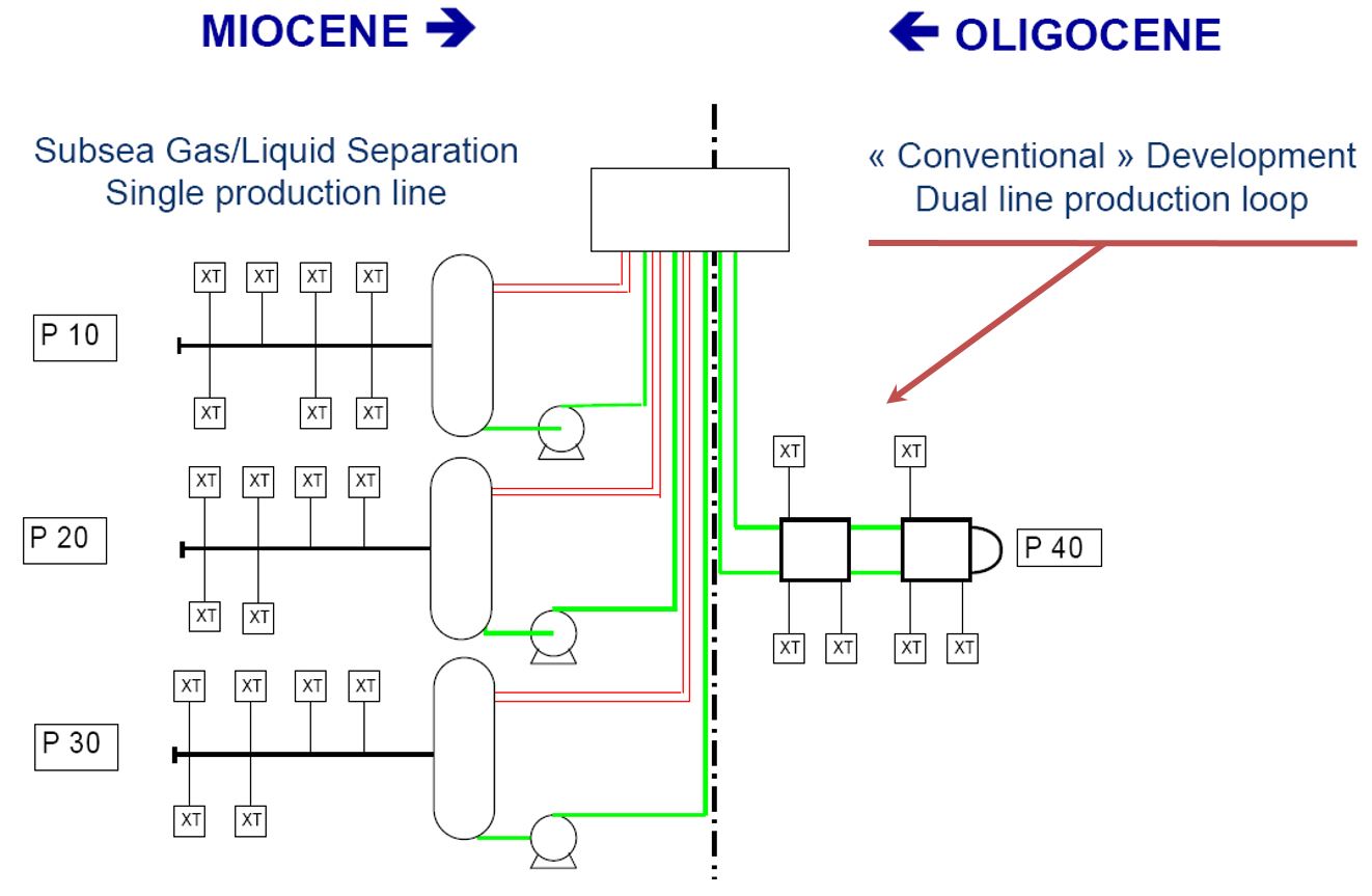
The Pazflor project uses such advantage. Indeed, the Pazflor oil field comprises four reservoirs. One of them, Acacia was formed in the Oligocene and contains light oil. The other three — Perpetua, Zinia and Hortensia — are younger, dating from the Miocene, and contain heavier and much more viscous oil. Consequently, subsea gas/liquid separation is the key to the economics of producing these challenging reservoirs.
The development of the Miocene part features single production flowlines connected each to a subsea separation unit, whose functions are:
To separate the gas from the fluids
To boost the liquids by means of dedicated pumping system.
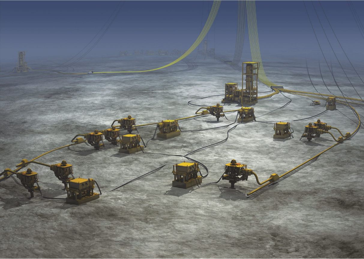
The subsea production system for Pazflor’s three Miocene reservoirs therefore includes three subsea separation units, each located near the first production well for a quick heat-up during a cold restart. Each unit consists of four retrievable packages:
A gas-liquid separator. Vertical separation modules were selected, instead of horizontal ones, to provide a smaller footprint
Two hybrid pumps to boost the liquids. Purpose-designed for Pazflor, the hybrid pumps were another world first. They combine multiphase stages, compatible with the presence of gas in the liquid, and a centrifugal stage, to improve efficiency,
A manifold to distribute the effluents to the separator and pumps.
The gas and liquids are transported up to the FPSO through separated risers (two gas risers and one liquid production riser per unit). The characteristics of the fluid allow for such a single flowline arrangement, with the possibility of an effective depressurisation of the production line (separator at lower pressure) as a remedial measure against hydrate formation. The entire subsea network is depressurized from XT choke to the separator via the gas lines of the SSU. The liquid line of the SSU naturally is outside the hydrates formation zone, since most of the light ends have been flashed off; no preservation against hydrates is performed on it.
Each SSU has its own power and control umbilical.
The Oligocene reservoir was developed using a standard production loop. Preservation is based on live oil displacement with stabilized oil. Reservoir pressure is maintained by combined water and gas injection: water in most of Oligocene horizons, and gas in Oligocene upper sands. One main common umbilical serves the production wells by manifold distribution system and flying leads, and the injection wells by dedicated injection umbilicals
Consequently, for Pazflor field development, two separate subsea production systems were developed to accommodate two types of oil with very different properties. Both systems were then connected to a single Floating Production, Storage and Offloading (FPSO) vessel. After departing South Korea on January 18 this year, the Pazflor FPSO is currently at sea, en route for Angola.
Figure 5.6 - Total's Pazflor development featuring single flowlines and subsea separation for the Miocene reservoir development
5.3.5 Cold Flow
Principle
BP and the SINTEF (Norwegian petroleum research institute) are developing a method for transporting multiphase flows over long distances at seawater ambient temperature. They hold a patent on a technology called Coldflow, which allow the transport of gas hydrates with the flow.
The principle is to ensure that the flow from a well is actually cooled down, rather than kept warm. The approach is founded on a better understanding of hydrate and wax formation.
Hydrates are lattice structures made of water molecules surrounding small gas molecules. In a production pipeline, these hydrates can go through the following phases:
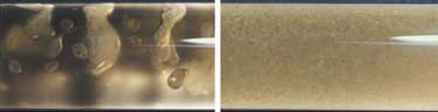
With the pressure and temperature decrease to reach the subsea well / flowline interface conditions, the hydrate crystals form. After a while, the crystals, which are hydrophilic, tend to grow as a thin layer on the outside of free water droplets. In this condition, the crystals tend to agglomerate together and to build up into long plugs that block the line. This effect is normally controlled by keeping the temperature up (e.g. by means of thermal insulation) or by continuous addition of anti-freeze chemicals (e.g. methanol).
However, if the pipeline conditions did not limit the hydrate formation process to the ‘plugging phase’, the crystals would ultimately become individual sub-millimetre particles that do not agglomerate. This stable state is similar to a dry powder suspended in liquid and allows the hydrates transportation by the fluid.
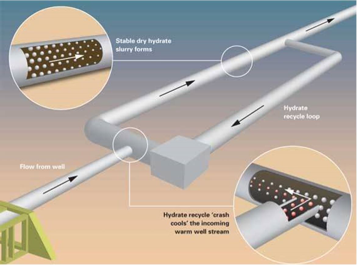
This latter condition is referred as the cold flow. It can be reached by mixing the hot well fluids rapidly with a cooled well-stream ('crash cooling') containing hydrate and wax particles that act as seed crystals. This causes the free water droplets to quickly coat the hydrates as a thin film, which then converts to hydrates and continue to grow outwards, absorbing more and eventually all of the water in the stream.
Future Applications
The theory of the Coldflow solution seems now well understood. Trials have been carried out on a test loop in Norway using oils from various BP oilfields. It is now being tested out at the SINTEF with a pilot loop to conduct scale-up tests.
The trials already performed have also shown encouraging results for controlling wax deposition. The mechanism behind the wax process is fundamentally the same as for hydrates: existing wax particles are mixed with the warm production stream, leading to preferential deposition on the existing wax, such minimising wall deposition.
In practice, the ‘crash cooling’ could be achieved by recycling a cold stream of stabilised dry hydrate, taken several kilometres downstream of the subsea well, and mixing it with the warmer stream near the wellhead. When the two oil flows meet each other, the oil in the warm well flow cools rapidly and the process induces further dry hydrate.
The formed effluent would be more viscous and hence would probably require a pumping system on the seabed. The subsea pump technology is well advanced () and would be available for such application.
The concept would allow oil to be transported in ordinary steel pipes without insulation. Only single lines, rather than loops, would be needed. Requirements for chemicals would also be reduced. The Coldflow would hence drastically decrease the cost of developments. It would also permit the transportation over long distances (as there is no further requirement in terms of thermal losses), allowing the development of satellite wells in a long distance tie-back configuration. This could be particularly interesting in northern regions where ice (Artic) conditions necessitate development on the sea bed and ultra-long multiphase transport ashore.
5.4 Injection Lines
The water and gas injection lines transport stable fluids and do not require any hydrate management action. Hence, they are generally simple bare pipes installed in a single line configuration.
They can be fitted with In-Line Tees (ILT) to connect some wells along their route with a FLET at the extremity connecting the last injection x-mas tree.
| Tip Click these links below for access to 3D resources: |
However recent corrosions (and stress-corrosion cracking) have been observed in water injection pipelines (e.g. bacteria’s corrosions at 6 o’clock position) require the use of inner coating, cladding or lining of water injection flowlines.
In addition to single water or gas injection, there is also the possibility to consider Water Alternating Gas (WAG) Injection. This enhanced oil recovery process consists in carrying out water injection and gas injection alternately for periods of time to provide better sweep efficiency and reduce gas channelling from injector to producer. This process is used mostly in CO2 floods to improve hydrocarbon contact time and sweep efficiency of the CO2.


