
6 Subsea Processing and Active Lifting
The active lifting envelops all the techniques which aim at enhancing the production. It includes the widely used ‘gas lift’ technology as well as the emerging subsea processing technologies, such as subsea separation and boosting.
This section summarises the different technologies that are susceptible to be employed for a deepwater subsea development requiring production enhancement, and to describe their impact on the project development and architecture.
6.1 Gas Lift
The gas lift consists in injecting a certain rate of gas into the production system. The injection can be basically performed in two areas:
In the well, this is then called downhole gas lift and can be used in direct vertical access or subsea wells.
In the flowline / riser, i.e. riser base gas lift which consists in injecting the gas at the seabed level.
The main purpose of the gas lift is to enhance the production by reducing the effluent density. It is usually used for cases where water cut is high, the fluid GOR is low or the reservoir pressure is moderate. The injection of gas allow to lower the flow path pressure by decreasing the liquid ratio and hence the density of the effluent along the column up to the floater.
Another application is to control the severe slugging, which can be created by downhill flow path, sags or other low points allowing accumulations. The gas injection would smooth and manage these surges, which are an issue for topside processing, e.g. separators.
Riser base gas lift can also help in case of riser / flowline depressurisation to treat a hydrate plug. It allows to more efficiently purge the riser with its liquid content and hence to fully depressurise the system. This method is now field proven for low water cut systems.
The gas requires to be transported at the seabed / downhole level. This can be performed through either dedicated riser(s) or integrated to production risers, e.g. Integrated Production Bundles (IPB, refer to ). Dedicated riser involves either a one-to-one development (i.e. one gas lift riser per production riser or well) or common bigger riser connected to subsea unit, which then dispatches the flow to the different flowlines or wells.
The required level of insulation of such riser need to be determined as part of the flow assurance and flowline thermal analysis studies.
In case of use of hybrid risers, the riser base gas lift can be achieved through the use of production PiP-SHR. In this configuration, the Gas Lift injection is obtained by means of an injection point, located inside the Bottom Assembly structure. The Inner Pipe (IP) provides a flow path for the production fluid, whereas the Outer Pipe (OP) allows an independent flow in the annulus for Gas Lift purposes. In this configuration, both IP and OP are insulated. This configuration has been successfully used on USAN and Kizomba B fields.
The source of lift-gas is generally the produced gas, which has been separated and treated on the floater.
6.2 Subsea Processing
6.2.1 General
Subsea processing technologies have been developed up to a relatively mature level and applications have increased rapidly in recent years, allowing them to be considered as important tools for field development. The subsea processing activities include any means of treatment (e.g. liquid/gas separation) and handling (e.g. boosting) of the produced fluid performed at the seafloor level, in particular:
Raw Water Separation
Gas/Liquid Separation
Gas Compression
Subsea Boosting / Pumping
The general benefits of subsea processing are the followings:
Increased or accelerated production
Increased recovery rate and extended production
Marginal field production is enabled (e.g. long tie-back or very deepwater fields)
Improved flow management (e.g. gas separation avoids slug appearance, water separation acts as hydrate prevention strategy, etc.)
Reduced CAPEX in some cases, by decreasing pipeline costs (single line versus loop lines) and topside costs.
The incentives for the use of subsea processing are hence (1) developing new fields with some additional economical incentives or (2) increasing the life and recovering rate of mature fields.
The subsea processing technologies are briefly presented in the following sections and further described in the document . They all have been developed to a maturity level which allow them to be used for deepwater developments with adequate qualifications (i.e. field applications or pilot already exist).
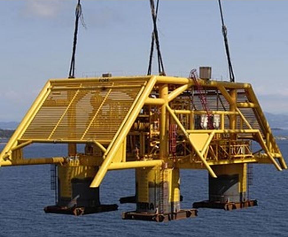
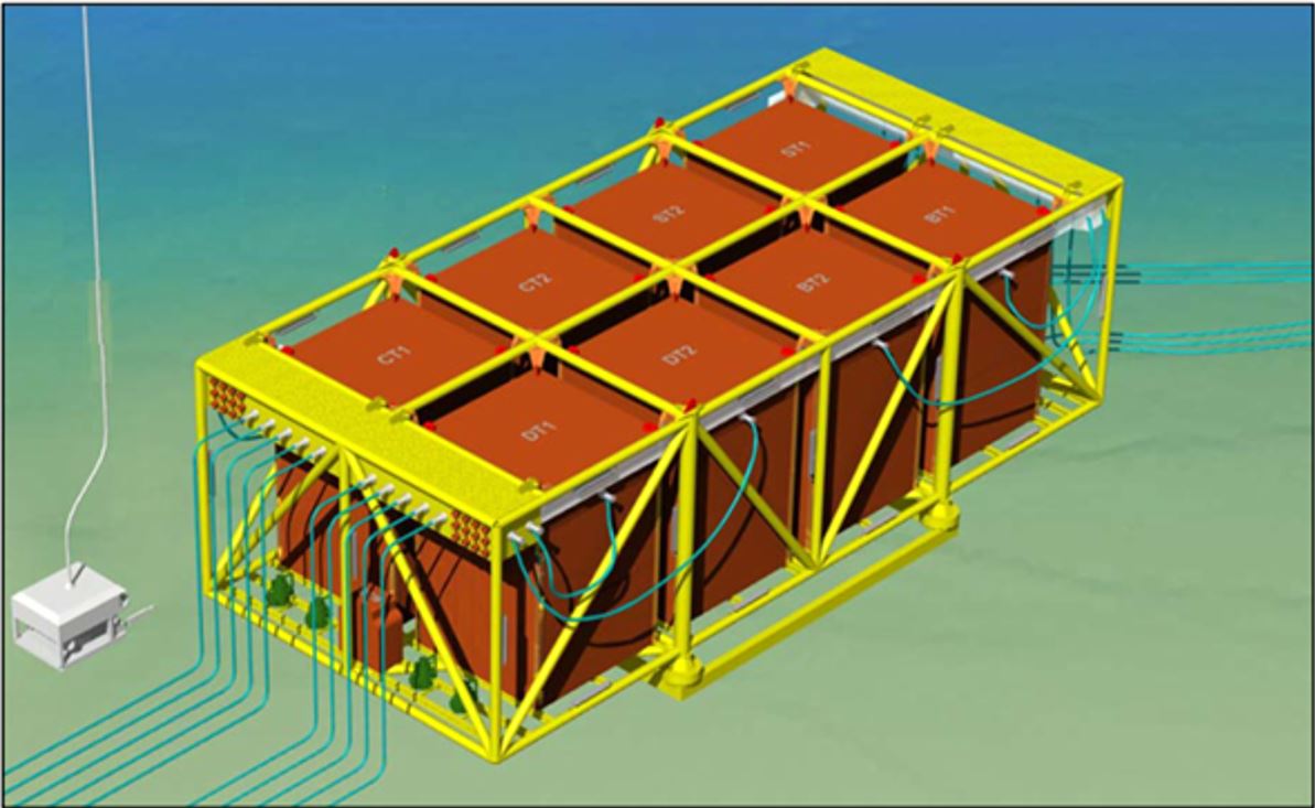
The implementation of subsea processing station involves installing large packages on the seabed (e.g. Tordis station, which separates water and sand from oil wells and pumps them downhole, is the world's heaviest subsea template. It weighs around 1,250 Tonnes, including a 170 Tonnes separator vessel, multiphase booster, water injection pumps and desander). It also requires ‘feeding’ the subsea units with electrical / hydraulic power through dedicated umbilicals (e.g. 2-4MW, 15kV).
6.2.2 Raw Water Separation
Raw water separation and re-injection in the reservoir brings the following advantages to the field developments:
Reduction of the transported fluid quantity, thus decreasing of the size and cost of pipelines and topsides equipment.
Reduction of the back pressure on the well, leading to increased oil and gas recovery or feasibility of longer distance tie-back.
Minimisation of the hydrate formation issues, i.e. less chemical requirements and thereby reducing the field OPEX.
The first system for deepwater subsea separation of heavy oil and water that includes reinjection of water to boost production in a mature field development was installed for Marlim field (Petrobras) in 2013.
6.2.3 Gas / Liquid Separation
The implementation of gas/liquid separation system allows the transportation of single phase fluids, with the advantages of reducing both the pressure drop and the slug issues. This is generally combined with a liquid boosting system (e.g. electrical subsea pump) as a single liquid phase can be more easily boosted, with the aim of benefiting of one or several of the following advantages:
increase the well flow-rates (i.e. higher production rate)
decrease the well abandonment pressure (i.e. longer field life / recovery rate)
Increase the transportation distance for deepwater fields or satellite accumulations development
The gas/liquid separation can also be implemented as a hydrate management tool, e.g. separation of gas from liquids by means of pressure reduction in the separator.
Gas / Liquid Separation modules are in operation in Parque Das Conchas (Shell), Tordis (Statoil), Perdido (Shell) and Pazflor (Total).
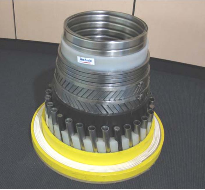
6.2.4 Gas Compression
The subsea gas compression is of high interest for subsea tie-back development of gas fields to avoid pressure depletion and to maintain satisfactory production rate during field lifetime. The main expected benefits from a subsea gas compression system are:
To be able to position the unit at close distance from the well to efficiently boost the gas (especially for long transportation and tied-back distance)
Avoid requirement for a compression platform while allowing development of reservoirs that would otherwise not be deemed as economical, i.e. by decreasing the overall CAPEX.
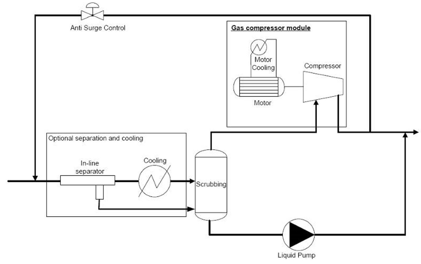
For subsea use a compressor must be very robust compared with a surface unit. In order to provide safe operational conditions for the compressor, the compression module is typically combined with a scrubber. Cooling and gas / liquid separation systems can also be included (with a liquid pump for the separated water) for more efficiency (see Figure 6.3, “Typical Subsea Gas Compression System Diagram (FMC Kongsberg)” below).
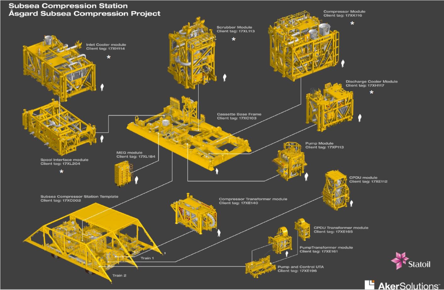
This gas compression technology has been used for the first time for Asgard project (Statoil). Composed of 13 subsea modules, the compression system designed by Aker was delivered and started-up in 2015.
This project, located in a water depth of 260 m, consisted in a 40km tie-back to Asgard A & B.
6.2.5 Subsea Pumping
The subsea pumping is the most mature technology, including both liquid and multiphase pumps. Their function is to add energy to the produced effluent and hence to enable the fluid to be transported over long distances, to increase the production rate or to maximise the recovery of oil/gas from the reservoirs.
Over the past 10 years, Subsea Multiphase Pumping has accomplished extraordinary technology breakthroughs. Initiated in 2006, the development of the OneSubsea MPP High boost, successfully achieved in 2011, pulverized a 17-year-old wall of 50 bar of delta pressure imposed by the MPP technology developed so far. Since then, the technology has never stopped beating records of output power, speed, wellhead shut-in pressure, viscous fluid pumped. The MPP system installed in Moho Nord 1bis pumping station allowed for a maximum differential pressure of 133.5bars, with a flowrate of 400m3/h, and a required power of 3 500kW. Refer to for further details.

Such multiphase pumping systems are currently in operations in several fields, including Girassol (GirRI project; Total), CLOV (Total), and Moho Nord (Total).
6.2.6 Chemical Injection
More and more new deepwater developments are based on the operation of remote marginal fields. Such developments do not justify a stand-alone hub and are therefore based on long subsea tie-backs to surface facilities that are located tens of kilometres away. Subsea production equipment of such tie-backs requires supply of various chemicals that are conveyed from the Floating Production Storage and Offloading vessel (FPSO) via umbilicals. Due to the increasing tie-back length and associated pressure drop, these umbilicals become larger and more complex.
As an alternative, studies are ongoing to assess the benefits of a chemical storage and injection subsea station that would allow removing chemical supply lines from the umbilical, in order to reduce umbilical complexity and cost.
The first outcomes of this assessment tends to show that choosing a chemical storage and injection subsea station, instead of a classical umbilical including chemical injection lines, could be profitable for wide range of configurations (depending on oil or gas field, water depth, tie back length or production profile).
After a first phase to assess the economical benefits of such a solution (described in a paper prepared jointly by DORIS and Total for DOT 2012 ‘Subsea Station for Chemical Storage and Injection’), this concept has then been developed on a case study development, including a prequalification study and a cost analysis.


