
4 Well Architecture
4.1 General
The determination of the well number and their best location is an iterative process that takes place early in the project. It is a trade-off between an effective drainage of the reservoirs (which tends to spread and maximise the wells count) and cost savings (which ask for a gathering of the wells in some limited areas, the 'drilling centres'). The grouping of the wells can (1) facilitate drilling operations and (2) save flowline cost by optimisation of the flowline total length.
Deepwater field developments can hence involves individual satellite wells (see Section Section 4.3, “Cluster System description” below), but more commonly grouped wells, which may be gathered in either a cluster or a well template, in which the well spacing is closely controlled by the template structure. These two options are further described in the following Sections Section 4.3, “Cluster System description” and Section 4.4, “Template System Description”, and discussed in Section Section 4.5, “Cluster vs Template Configuration”. Refer also to document for further details on the Subsea Production Systems.
4.2 Satellite Wells
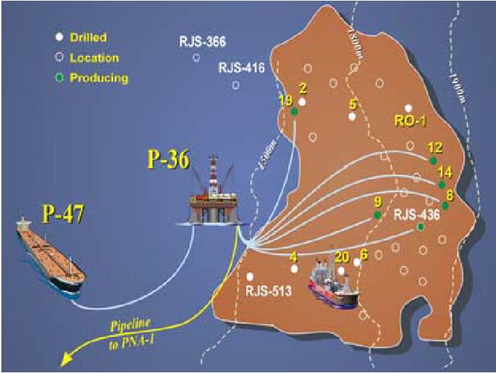
Individual subsea wells are typically used for small developments requiring few wells. These fields generally feature widely spread wells and production is transported to the host platform through a single flowline for each well.
Such type of development (one line per well) are mainly found in Brazil (see Figure 4.1, “Roncador Field Development (Module 1)” depicting the Roncador field, module 1), where a well established flexible pipe local market allowed for a reduction in flexible pipes high manufacturing cost with regard to the optimisation of the well location plan.
4.3 Cluster System description
Clustered wells are basically single satellite wells arranged around a subsea manifold assembly that collects, commingles and exports flow to a surface facility. Each ‘satellite’ well is connected to the manifold by (well) jumpers and umbilical (flying leads), and hence a connection jumper from each well to the manifold is required.
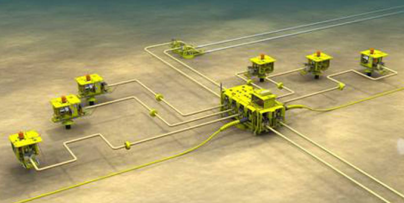
In such configuration, wells may be placed from several meters to tens of meters from one another. This distance is a balance between the desire to minimize the drilling risks and an optimization of the well jumper overall size.
The cluster configuration allows for some margin in the performance of the drilling operations, e.g. well re-spud few meters away from a first aborted drilling is feasible. It also allows for more flexibility in term of planning by decoupling the SPS and drilling schedules. Refer to Section Section 4.5, “Cluster vs Template Configuration” for further 'pros and cons' considerations.
![[Tip]](tip.png) | Tip Click these links below for access to 3D resources: |
4.4 Template System Description
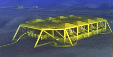
The template wells option is a configuration where manifold and wells are gathered onto a common steel support structure and foundation.
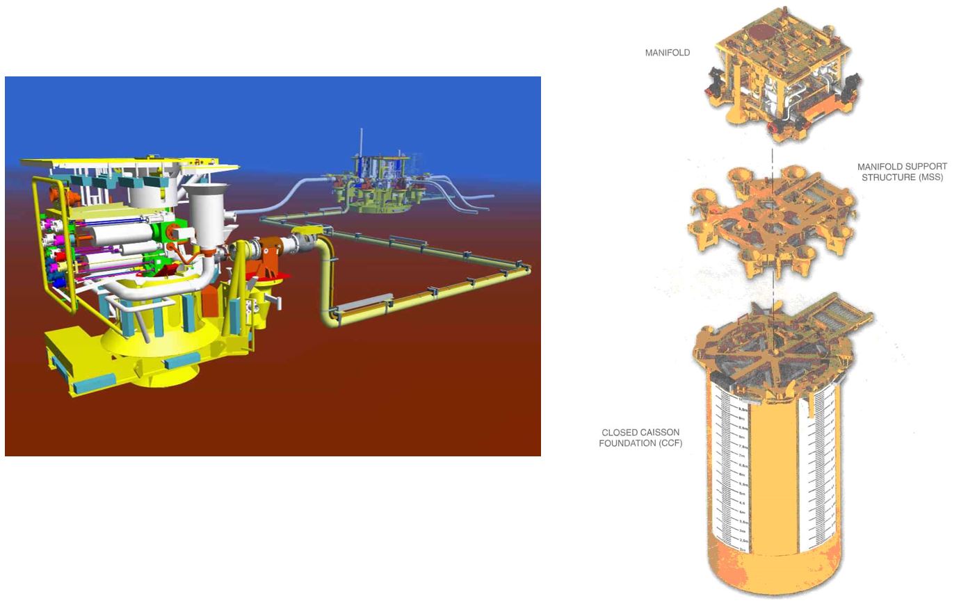
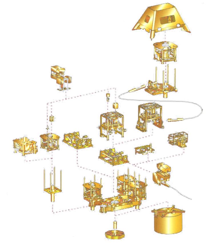
A typical template manifold system is composed of the manifold module, x-mas tree systems, template base, foundation and protection structure. The manifold is installed centrally on the template base. The manifold and x-mas trees include the same functionality as the equivalent systems in the cluster configuration, but with the addition of horizontal connector and flow-loop (connection ‘flexibility’), which are stroked forward during the tie-in operation. The template base provides guidance and landing for the manifold, interfaces for pigging loop, flowline tie-in, and well bays for positioning of the surface casings, and hence the x-mas trees once installed. Well bay spacing is designed to accommodate the BOP and x-mas tree envelope dimensions. The system may also include protection structures, depending on impact and snag loading requirements.
The main advantages of a template system are related to the elimination of the production well jumpers, as it removes a potentially difficult SPS / UFL contractor interface, simplifies drill centre layout and minimizes the subsea connections (potential sources of leak). It can also provide a number of cost and schedule benefits (decreasing of vessel operation duration: neither metrology nor jumper installation to be performed).
The main issue related with the template configuration is drilling risk. The compact layout increases the criticality of the drilling operations, which are performed through the template system and could directly impact its structure, e.g. loss of a slot or destabilisation of the template system foundation. Refer to Section Section 4.5, “Cluster vs Template Configuration” for further 'pros and cons' considerations.
The Templates can be classified into two broad categories:
Modular construction
Single piece structure
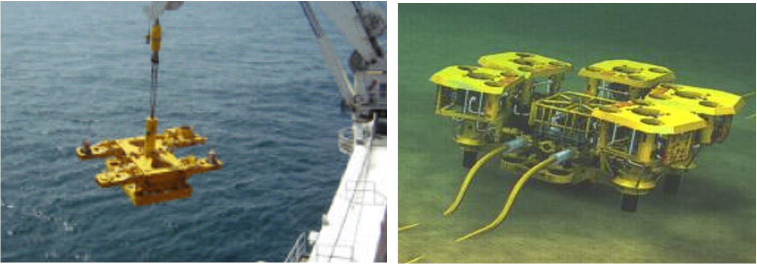
The modular systems are based upon a set of standard, interchangeable modules and are specified where there is a stringent weight and size limitations on the template base. The system consists of a central template with separate foundation system and with manifold headers commingling the flow from production trees. The last manifold headers may incorporate a pigging loop when the ‘on-line’ production loop is adopted (see Chapter 5, Flowline System Architecture ). The template design may provide provisions to tie-in satellite production trees.
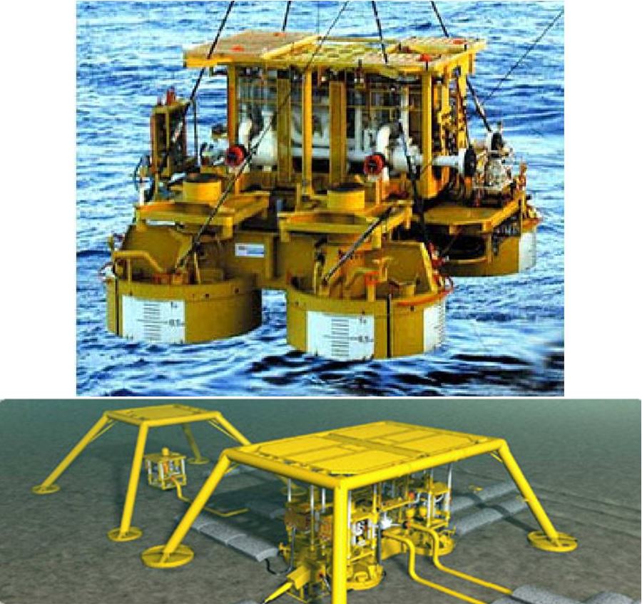
Single piece structures integrate foundation in the template base. Foundations can be spud-cans, suction caissons, skirts or a combination of skirts and suction caissons, as for the Ormen Lange 8-slot production template ( located at 800-1100 meter water depth and supplied by FMC/Kongsberg (see Figure 4.6, “Ormen Lange 8-slot template (42x26mx12m - 1150t)”).
The template base supports the manifold module (usually retrievable) and the well bays which act as guide bases and spacers for positioning the surface casing and hence the Xmas trees once installed.
4.5 Cluster vs Template Configuration
Both cluster and template configurations have been widely used for deepwater field developments. The main pros and cons of the systems are detailed below.
Main advantages related to the Cluster system are as follows:
SPS and drilling schedule implications
The template systems have to be installed at the start of the drilling program. This requires performing the design, fabrication, testing, shipping and installation of the template bases prior the first production well drilling. Thus critical path element is added to the SPS schedule by a template configuration.
Integration testing
The integration test of the template with manifold module, xmas tree, etc. requires:
Either that all these components are available within the delivery schedule for the first template, which is generally unlikely as it imposes very high schedule constraints for their design and construction.
Or the integration testing to be performed with dummy or partially completed equipment, thus increasing the risk of interface problems or clashes.
Installation cost (vessel mobilisation for template installation)
The drilling campaign is generally scheduled to commence prior to the flowline installation phase. Hence this can imply that an additional construction vessel is mobilised for template installation. Alternatives for avoiding this additional mobilisation are to perform template installation using (a) a vessel of opportunity from another project in the region (if any) or (b) using the drilling rig. This latter option would require a modular design, which is moonpool deployable (i.e. the HOSTTM system), which would limit SPS supplier competition, and consume drilling rig time (high day-rate for deepwater rig).
Proximity of wells
During the drilling riser disconnection and disengagement, the LMRP or BOP can swing towards adjacent wells. In the template arrangement, adjacent wells are in close proximity, so the risk of collision is high compared with a cluster arrangement. However, the implementation of guidance / protection structures is possible to avoid clashing of equipment. In addition, if dual well/completion operations from a dual derrick drilling rig are contemplated, it may be an advantage to have wells within close proximity.
Weight and size of structures
With the exception of a modular template design, the weight and size of template system components are generally greater than the equivalent cluster system, e.g. Ormen Lange template Figure 4.7.
Soil conditions and subsidence
The template position/tilting shall be kept within acceptable tolerances by its foundation system despite the soil subsidence, drilling and connection operations.
Main advantages related to the Template system are as follows:
Well jumper installation
For a cluster arrangement, a metrology of the relative x-mas tree / manifold hubs to be connected is performed prior the well jumpers fabrication. For the template system, connections are pre-aligned and the connection is directly performed by ROV tooling. The required vessel operation durations are hence minimised. The simpler connection (ROV only is required) could be a significant advantage for a phased development where a suitable vessel for installation of well jumpers is not available for the entire construction phase.
However, in most cases, it is possible to design ‘U’ shaped well jumpers which are sufficiently compact and light to allow installation by an available infield drilling rig support vessel.
Flow assurance
For the template system, preservation of well jumpers by methanol injection is not required. The volumes of chemicals to be injected are slightly reduced, increasing the time available for flowline preservation and therefore relaxing the cool-down time required for flowlines, which in turn could reduce the flowline insulation requirements. The template system would also provide the advantage of reduced high points in the system.
Overtrawling aspects:
In some fields, the fishing activities are very developed and induce a significant risk of interferences between fishing trawls and installed subsea equipment. In such cases, a Template Protective Structure will provide protection to all sensitive equipment (XT, piping, valves, connectors) against dropped objects and trawl impact, which can be a key driver for template architecture selection against a cluster design.


