3 Water / Hydrocarbon Separation
3.1 General
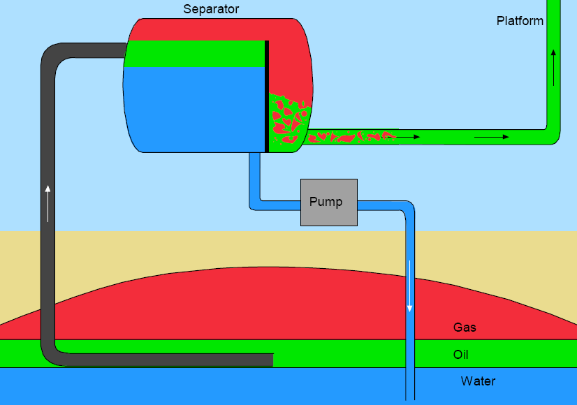
Removing produced water from the well-stream and re-injecting it into the reservoir brings the following advantages to both new and mature field developments:
Reduction of the transported fluid quantity, thus decreasing of the size and cost of pipelines and topsides equipment.
Reduction of the back pressure on the well, leading to increased oil and gas recovery or feasibility of long distance tie-back.
Minimisation of the hydrate formation issues, i.e. less chemical requirements and OPEX.
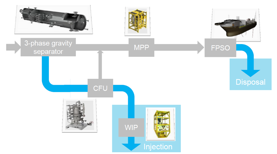
A subsea water separation system comprises a separator and a water injection pump as the main components. It shall also be able to eventually handle solid elements (e.g. sand) and can include a multiphase pump to boost the production. The Troll Pilot project was the first to implement the raw water separation / re-injection. It successfully came on-stream in 2001. Various projects now make use of subsea raw water injection.
The liquid / liquid separation can be based on different technologies:
Horizontal gravity separator vessel (which has been selected for the Troll Pilot and Tordis SSBI applications, refer to Section 3.4, “Troll Pilot Project”, and Section 3.5, “Tordis SSBI Project”)
Statoil / CDS In-line separation
Hydro Pipe-Separator project.
![[Tip]](tip.png) | Tip Click these links below for access to 3D resources: |
3.2 Separation Technologies
3.2.1 Gravity Separator
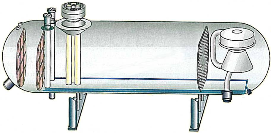
The gravity separator bases its principle on the different densities of the fluid components and the motive force of the gravity. It is the most common separation principle found in topside applications and allow for a simple system capable of meeting typical oil/water separation requirements (i.e. typically oil quantity inferior to 1000ppm in the water, to be compared to a range of less than 100-200ppm for similar topside equipment).
The entry in the separator system is done through a cyclone system which allows decreasing of the mixed fluid momentum. In order to obtain a proper and calm flow pattern in the vessel, some internal baffles may be included. The water level in the separator is controlled by the water injection pump. The oil and gas are typically re-combined for transportation to the platform through a dedicated outlet, which regulates the oil quantity in the re-mixed effluent to ensure smooth flow conditions out of the separator. Refer to Section 3.4, “Troll Pilot Project” (Troll Pilot) and Section 3.5, “Tordis SSBI Project” (Tordis SSBI) for further details. The separator vessel dimensions are dictated by the required retention time to allow the fluids to be separated and by the required throughput rates. One of the main subsea separation station design issue is to minimise the overall vessel size and weight.
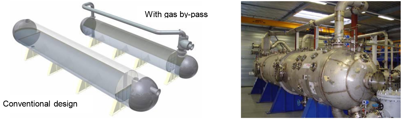
The Tordis SSBI separator is fitted with a FMC Technologies patented gas by-pass, which allows for a reduction of the vessel cross sectional area by maximizing the vessel volume utilisation for the oil/water separation.
3.2.2 In-Line Separator
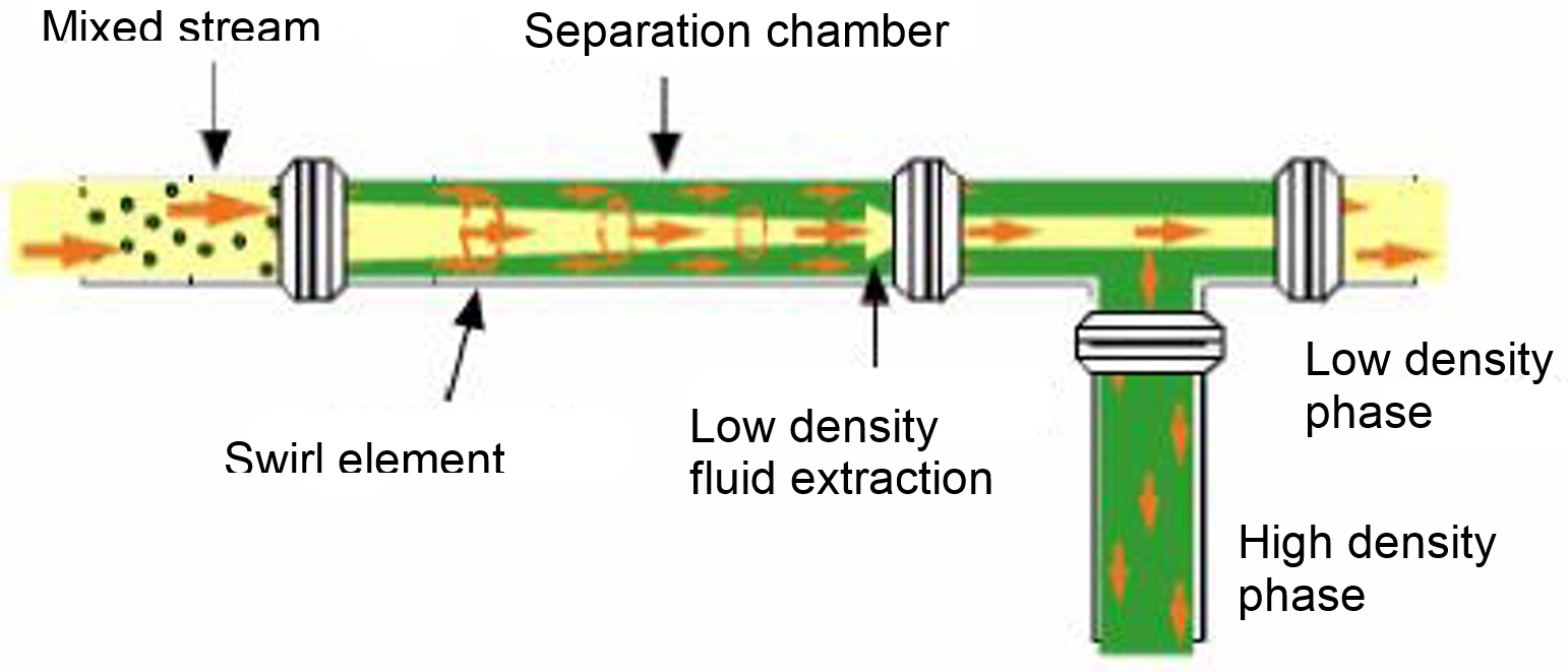
In-line cyclonic oil/water separation technology for subsea use has been developed due to its weight and size saving potential. The In-line separation technology allows for compact and efficient separation using the principle of high centrifugal force generated by swirling flow. The magnitude of g-force applied on the fluid is hence many times the gravity and it allows for very compact units manufacturing.
Such systems are installed and are adapted to large water depths and difficult to separate oil-water mixtures.
The in-line separation systems family includes in-line liquid/liquid (oil and water) separator, gas/liquid separator, de-sander and electrostatic coalescer.
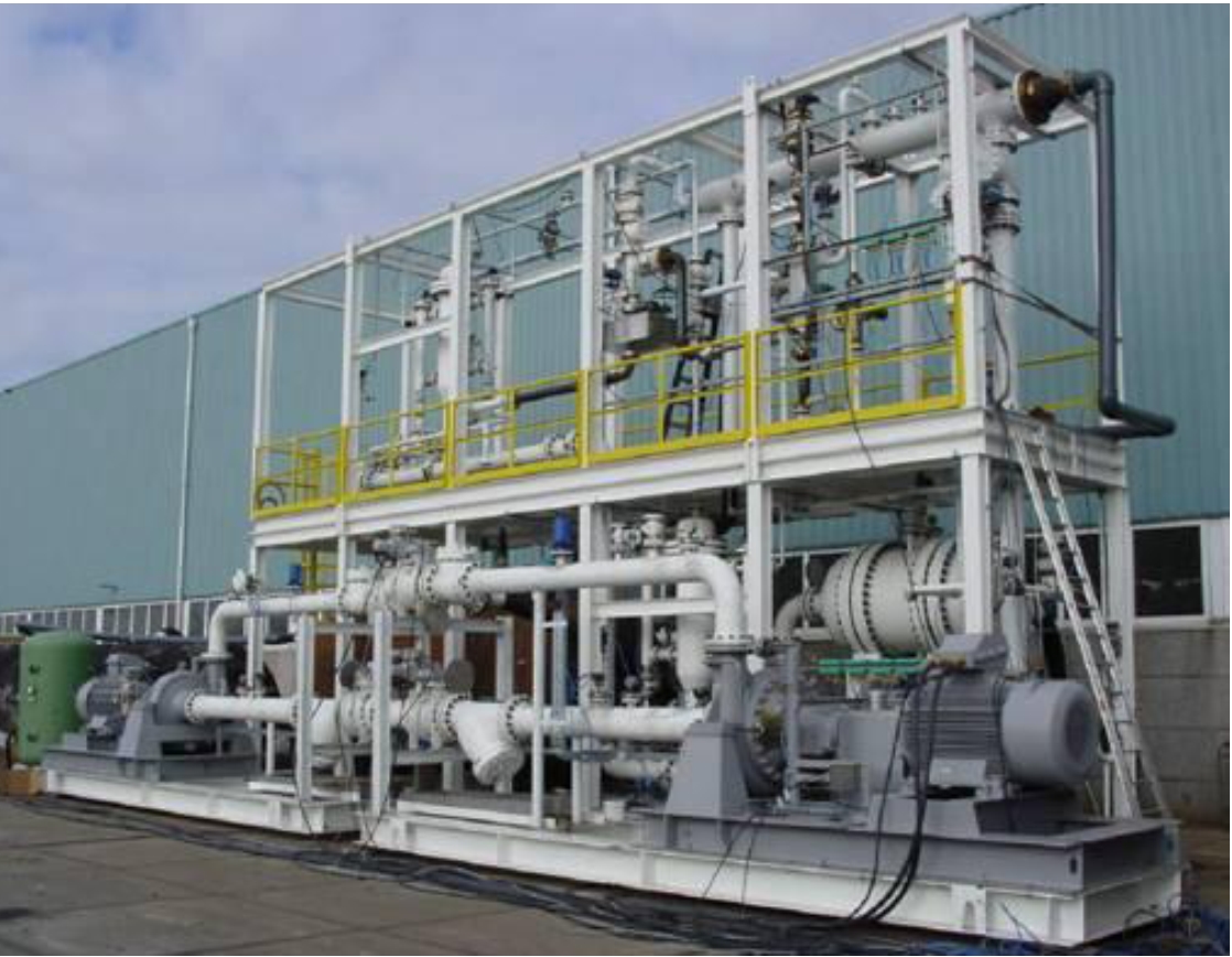
The in-line separation principle is now applied through the three-phase separation skid for Shell / PDO in Oman (onshore). This is the first application for in-line oil/water separation. It would allow testing these units and would be a step towards subsea applications.
3.2.3 Hydro Pipe-Separator
The Pipe-Separator technology is developed by Norsk Hydro for liquid/liquid separation. Studies and tests already performed aim at developing a compact system valid for deepwaters.
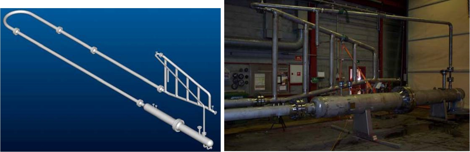
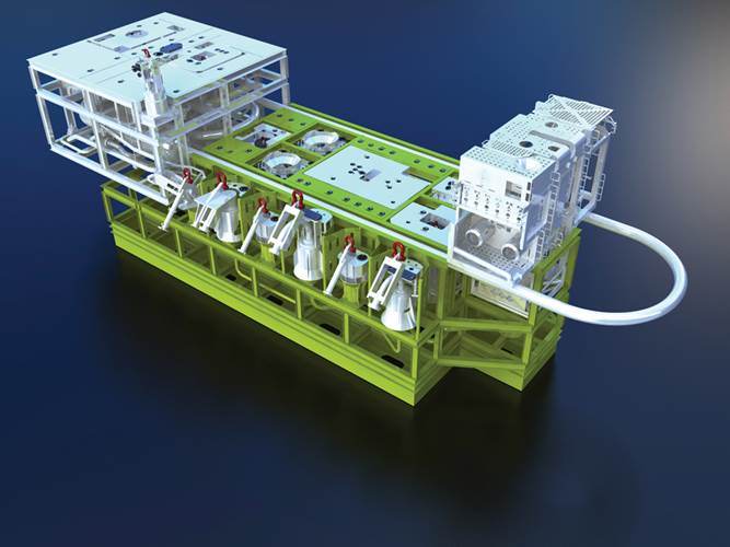
The Figure 3.5, “FMC Subsea Separation System Study featuring Pipe-Separator” below depicts a possible design of a subsea oil/water separation system using the Pipe-Separator integrated onto a FMC Technologies system.

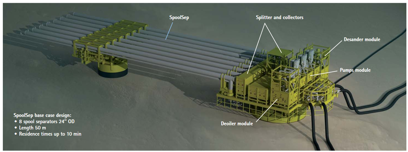
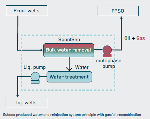
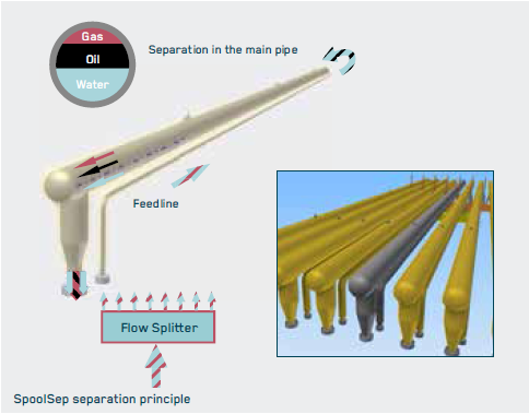
Another example of similar technology that relies mainly on pipe is the SpoolSep (SAIPEM) which can be used with or without electrocoalescer.
3.3 Enhancement of water / oil separation
Depending on separation technology efficiency and target level of Oil-In-Water, a treatment operation will be required to remove more oil to produced raw water. This can be achieved for example by Subsea Compact Flotation Unit (CFU).
CFU are under evaluation for use in produced water treatment (to further decrease oil in water).
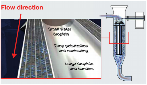
Electrostatic coalescence is used in surface (topside) separation equipment. It is based on gravity vessel equipped with grid of high voltage electrodes suspended in the fluid to induce an electric field. It causes the water droplets to be self-attracted and to coalesce to form larger droplets, which hence accelerate the gravity separation process. A compact electrocoalescer developed by FMC Technologies, InLine ElectroCoalescer, can be fitted into pipeline upstream of separator.
Statoil patented Compact Electrostatic Coalescer (CECTM) technology to allow subsea applications of the electrocoalescer technology. The CEC particularity is to use a series of concentric circular electrodes which accelerates the coalescing phenomenon compared to conventional grid electrodes. This technology subsea application purposes would hence (1) to allow decreasing of the vessel dimensions when compared to a conventional separator and (2) to further reduce the outlet water cut, towards the complete water separation process on seabed.
3.4 Troll Pilot Project
The Statoil (this pilot was initially initiated by Norsk Hydro Oil and Gas division that has been bought by Statoil in 2006) Troll Pilot Subsea separation system has been installed in 2000 on Troll C in approx. 330m water depth. Its function is to separate raw water from produced fluid and to re-inject the separated water into reservoir (e.g. maintain reservoir pressure for oil production).
3.4.1 The Separation Principle
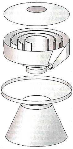
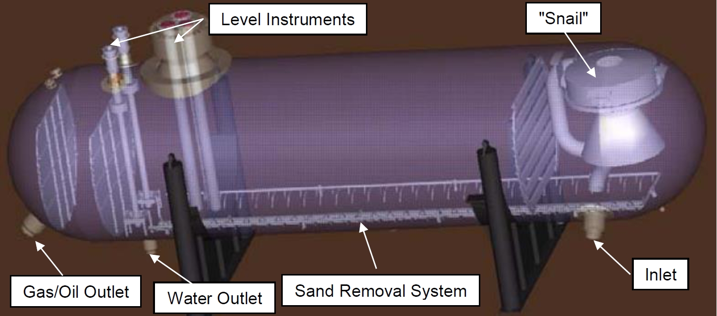
The Troll Pilot features a three phase separation system which is also capable of removing sand from the fluids.
The produced fluids enter the separator through the “snail”, passing around its spiral which allow for gradual reduction of the fluid momentum. Gas leaves via the open top while oil and water descend into the liquid phase. The Troll Pilot system is based on a gravity separator. Water and oil are separated by decantation phenomenon in the 9m long 2.8m diameter vessel. The sand deposits on the vessel bottom and is regularly flushed by means of the sand removal system.
Oil and gas are recombined and exit the system through a single flowline.
3.4.2 Project Description
The contract has been awarded to ABB Offshore (part of GE since 2007) in June 1997.
The installation operations were performed as follows:
Template with separator and Bridge Module installed in September 1999
Power/control umbilical installed in April 2000
Water injection well drilled during spring 2000
The system came on-stream in 2001.
3.4.3 Pilot System Description
The system features a three phase separator and a high powered electrically driven subsea pump.
The Separator
The Troll Pilot separator design parameters are the followings:
Liquid : 10 000 m3/day
Water : 6 000 m3/day
Oil : 4 000 m³/day
Gas: 800 000 Sm3/day
Water Cut: 90 %
The produced fluids enter the separator through the “snail”, which allow for fluid momentum decrease. Gas leaves via the open top while oil and water descend into the liquid phase via a submerged skirt. The skirt also enables any gas entrained in the liquid to be released over a lip.
The reinjected water quality corresponds to an oil quantity inferior to 1000ppm. Produced water is reduced from 90% water cut (design value, see above) to 10%.
The level of the oil/water interface is continuously monitored as this key parameter is used to control the speed of the re-injection pump.
The Subsea Pump
The Water Pump design parameters are the followings:
Head (dP): 151 bar
Flow rate: 6 000 m3/day
Speed: 3600 rpm
Power: 2000 kW (2MW)
Shaft power: 1500 kW (1.5MW)
The Framo Engineering (now OneSubsea, which is a joint venture 100% owned by Schumberger) vertical high voltage pump (Figure 3.11) is used on the system.
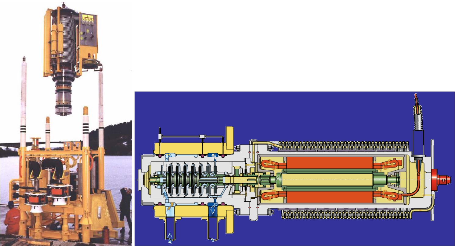
Electrical power for operating the high voltage water re-injection pump is delivered subsea via an umbilical, requiring a high voltage connector. The ABB connector has been originally installed. Consecutively to an earth fault (2000-2001), new 3-phases 12 kV ABB Mecon and Tronic wet mateable connectors (refer to ???) were successfully tested. The ABB Mecon system has been finally installed.
3.5 Tordis SSBI Project
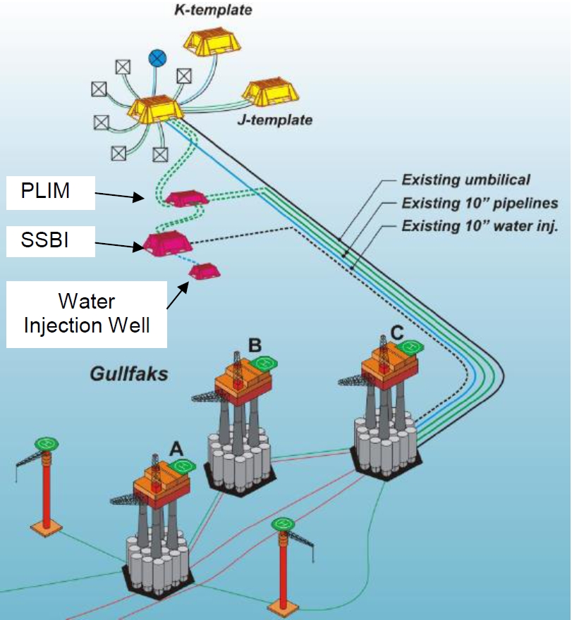
Statoil's Tordis is an 11km tie-back to Gullfaks C development, on stream since 1994 and located in 200m water depth. Due to the decreasing wellhead pressure and increasing water cut, FMC Technologies (now TechnipFMC) was tasked to develop the Tordis Subsea Separation Boosting and Injection (SSBI) unit. The system allows separating the raw water from the produced fluids and to re-inject it into reservoirs. An increase of the oil recovery from 49% to 55% was expected by reducing the back pressure from the mature producing wells.
Subsea separator was installed in 2007. Subsea water injection was stopped in 2008 due to formation fracturation up to the seabed. Water is now exported to Gullfaks C.
3.5.1 The Separation Principle
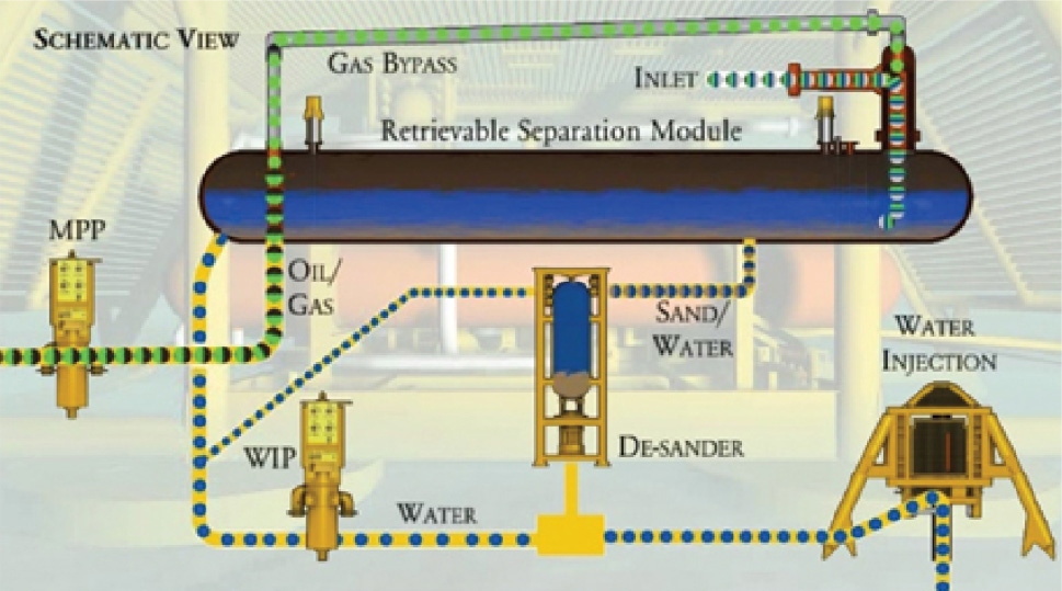
The system uses a gravity separator. The produced fluids enter through an inlet cyclone, which main function is to decrease the fluid momentum. A FMC patented gas by-pass system is connected at its top and allows for a first separation of the gas from the other fluids. It hence results in a reduction of the overall separator vessel dimensions.
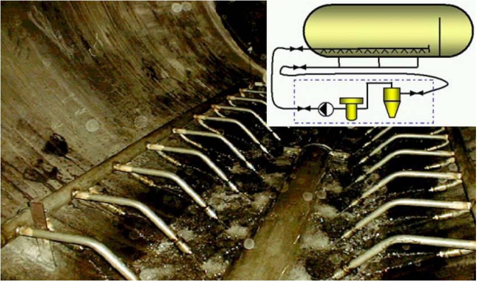
The fluids are separated in the vessel by decantation method. The raw water is re-injected in the reservoirs by means of a Subsea Water Injection Pump and one single Water Injection Well. The system is equipped with a sand removal system. The sand is flushed from the vessel bottom and temporarily stocked in a dedicated unit prior re-injection in the Water Injection system downstream the water subsea pump.
Oil and gas are recombined and exit the system through a single flowline fitted with a subsea MultiPhase Pump.
3.5.2 Project Description
The Tordis SSBI project milestones are the followings:
Milestones 2006
Milestones 2007
The qualification program performed on the project covers five main issues:
Qualification of the desander system
Evaluation of the subsea separation system performance
Optimisation and testing of the pumping systems (one water injection pump and one multiphase pump)
Testing of valves operated in sand slurry
Qualification of the 36kV dry mate high voltage connector (???). This qualification is performed in the frame of the Tordis project but considers the requirement for other future subsea pumping applications, as the Tordis requirements were initially for a 24kV connector (used in combination with a subsea transformer, which was no longer considered) and no dry mate connector is finally considered.
3.5.3 System Description
The FMC SSBI system includes:
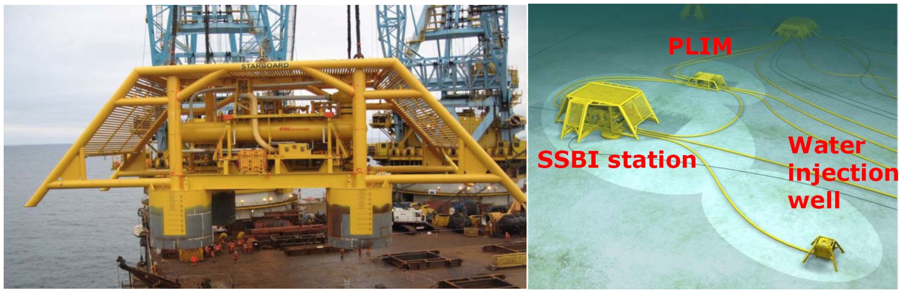
A pipeline in-line manifold (PLIM), which allow re-routing of the produced fluids through the SSBI itself
Subsea 3 phases separator
MultiPhase (oil/gas) Pumping system (OneSubsea, see Chapter 7, Submersible Pumps)
De-sander system
Water Injection Pump (OneSubsea)
Water Injection Well
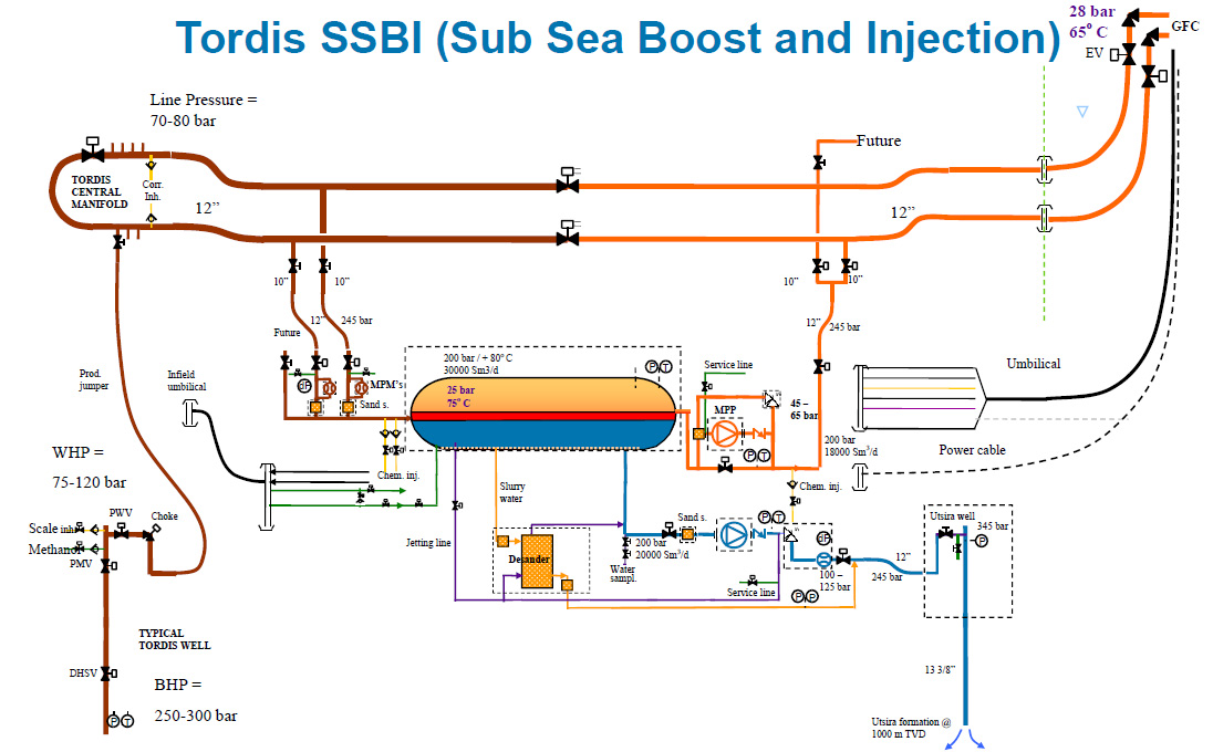
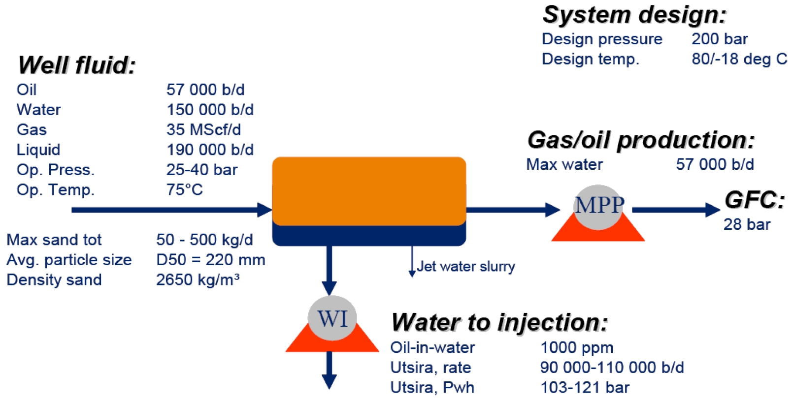
The following Figure 3.16, “Tordis SSBI System Design Basis” summarises the design basis of the system:
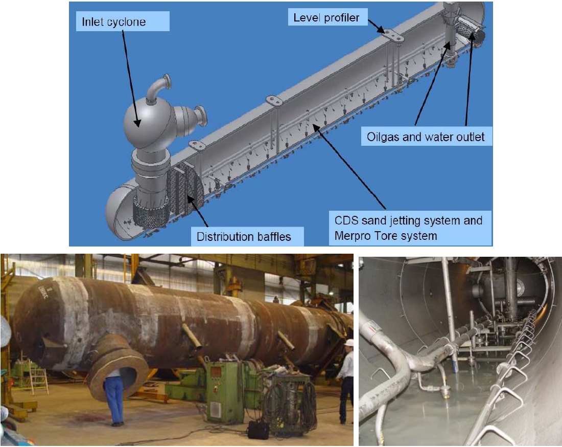
The Separator and its main components are depicted on the following Figure 3.17, “The Tordis SSBI Separator and Details of the Sand Jetting System”:
3.6 Marlim project
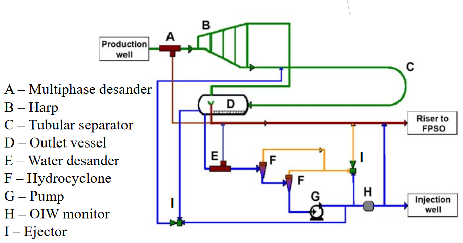
Marlim field is a Petrobas operated field in Campos basin. The Marlim Subsea Oil and Water Separation and Water Re-injection System (SSAO) is an innovative pilot project installed in 2013 as a Pilot System for the well MRL-141, connected to the host production unit (FPSO), P-37, in Marlim Field, Campos Basin. The objectives of the project are: platform debottlenecking of the water treating facilities; increasing production by reduction of back pressure on the wellhead. Besides these objectives, another important aim of the project is to prove the concept and qualify the adopted technologies for future other applications. As a pilot project, the SSAO was designed to work for a minimum of 5 years, without retrieving of any components, removing, treating and re-injecting free water from the production of MRL-141.
The system developed by TechnipFMC is based on a HARP (B) for degassing, a pipe separator (C) to segregate water and oil and a small vessel (D) to split the phases (this is based on STATOIL patents).