
8 Multiphase Pumping Systems
8.1 General
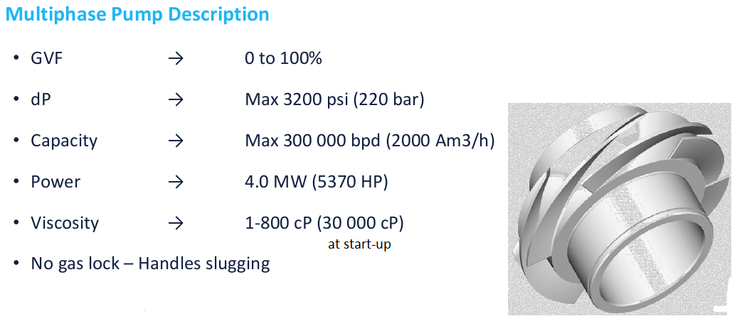
The multiphase pump is a boosting system capable of handling wide range of Gas Volume Fraction (GVF), i.e. effluents from fully liquid phase up to 95%-100% of gas. It is based on two technologies: the helico-axial or the twin screws systems. Both are fully proven technique through numerous surface (onshore and offshore) and subsea applications.
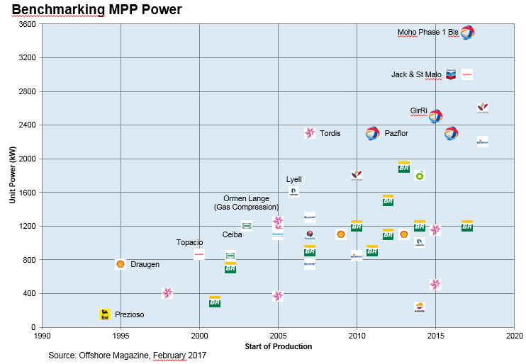
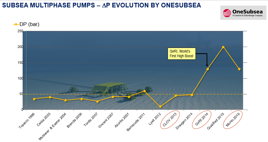
Over the past 10 years, Subsea Multiphase Pumping has accomplished extraordinary technology breakthroughs. Initiated in 2006, the development of the OneSubsea MPP High boost, successfully achieved in 2011, pulverized a 17-year-old wall of 50 bar of delta pressure imposed by the MPP technology developed so far. Since then, the technology has never stopped beating records of output power, speed, wellhead shut-in pressure, DP, viscous fluid pumped.
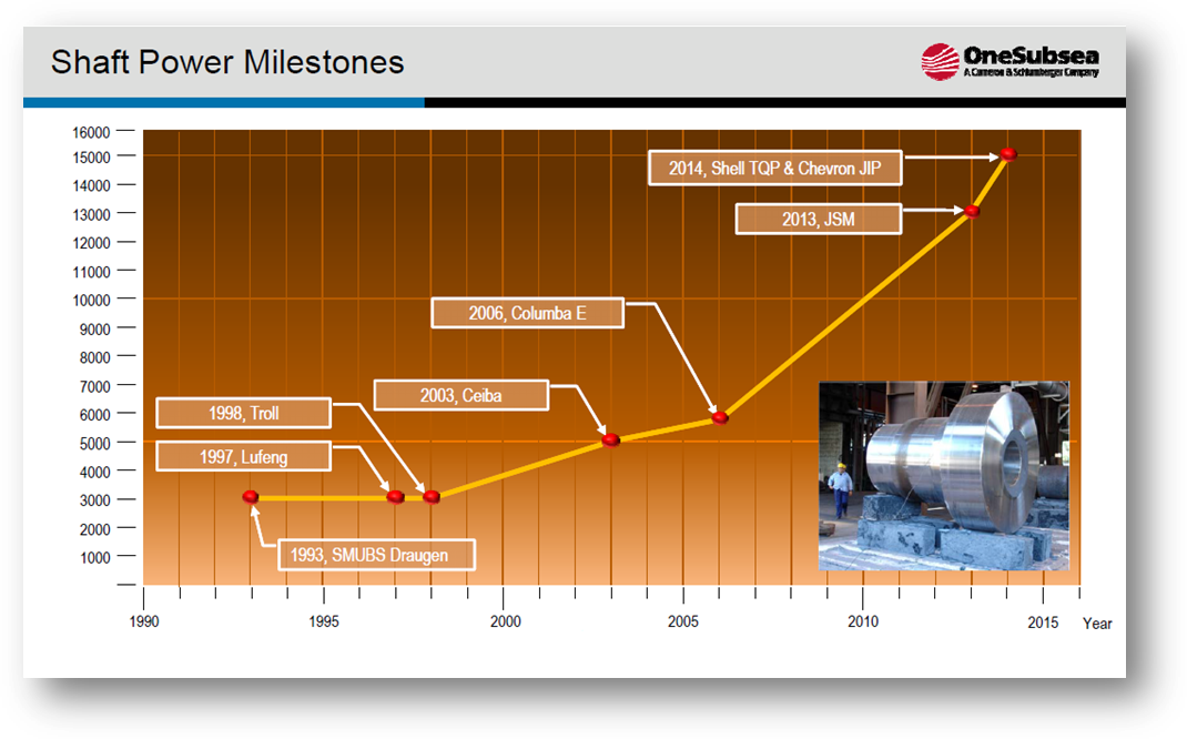
Today, multiphase pumps (MPPs) are generally accepted as qualified and used Worldwide. So the need and the potential of the technology are understood. In terms of technological achievements, the available qualified technology is able to deliver a shaft power up to 3.8MW, to run up to 6000rpm, to generate a DeltaP of 215bar at 60% GVF, and to resist to a wellhead shut-in pressure of 15kpsi. In terms of reliability, existing systems are well above the industry target of having 90% of probability of surviving 5 years.
Multiphase pumps are used in very versatile applications. They can be deployed for multiphase fluid transportation, i.e. to bring back the production to the FPSO. This is typically the case when the MPP station is located far away from the FPSO. The MPP DP is then used to increase the discharge pressure to overcome the pressure losses. A multiphase pump can be utilized also to increase production and reserves. This is the case when the MPP DP is used to lower the WHFP. Recently, an MPP was put into service to produce a very high viscous fluid, with an emulsion viscosity of 800cP.
![[Tip]](tip.png) | Tip Click these links below for access to 3D resources: |
8.2 Multiphase Helico-Axial Pumps
8.2.1 General
The helico-axial pump is a rotodynamic turbo-machine, which is capable of handling raw effluent, i.e. a mixture of oil gas, formation water and a certain amount of solids (e.g.sands). The helico-axial technology has been developed by the "Poseidon" group: Institut Français du Pétrole, Total and Statoil.
8.2.2 Technical Description
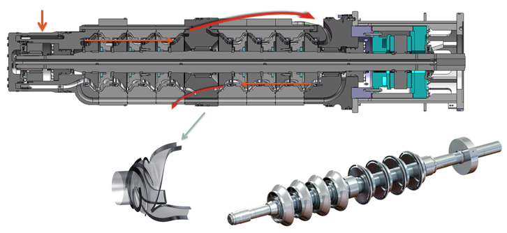
Multiphase helico-axial pumps are multi-staged pumps. Each stage is composed of a rotating part, the impeller, and a static part, the rectifier or fixed diffuser. The number of stages depends on the required head. Typical helico-axial internal elements are shown in Figure 8.1, “Internals of the Helico-axial pump (Technology developed by IFP, Total & Statoil)”.
The special shape of the impeller (rotating part) limits accelerations and also low-pressure zones. It avoids the gas-liquid mixture separation and facilitates the gas carry over, providing good performance in multiphase flow.
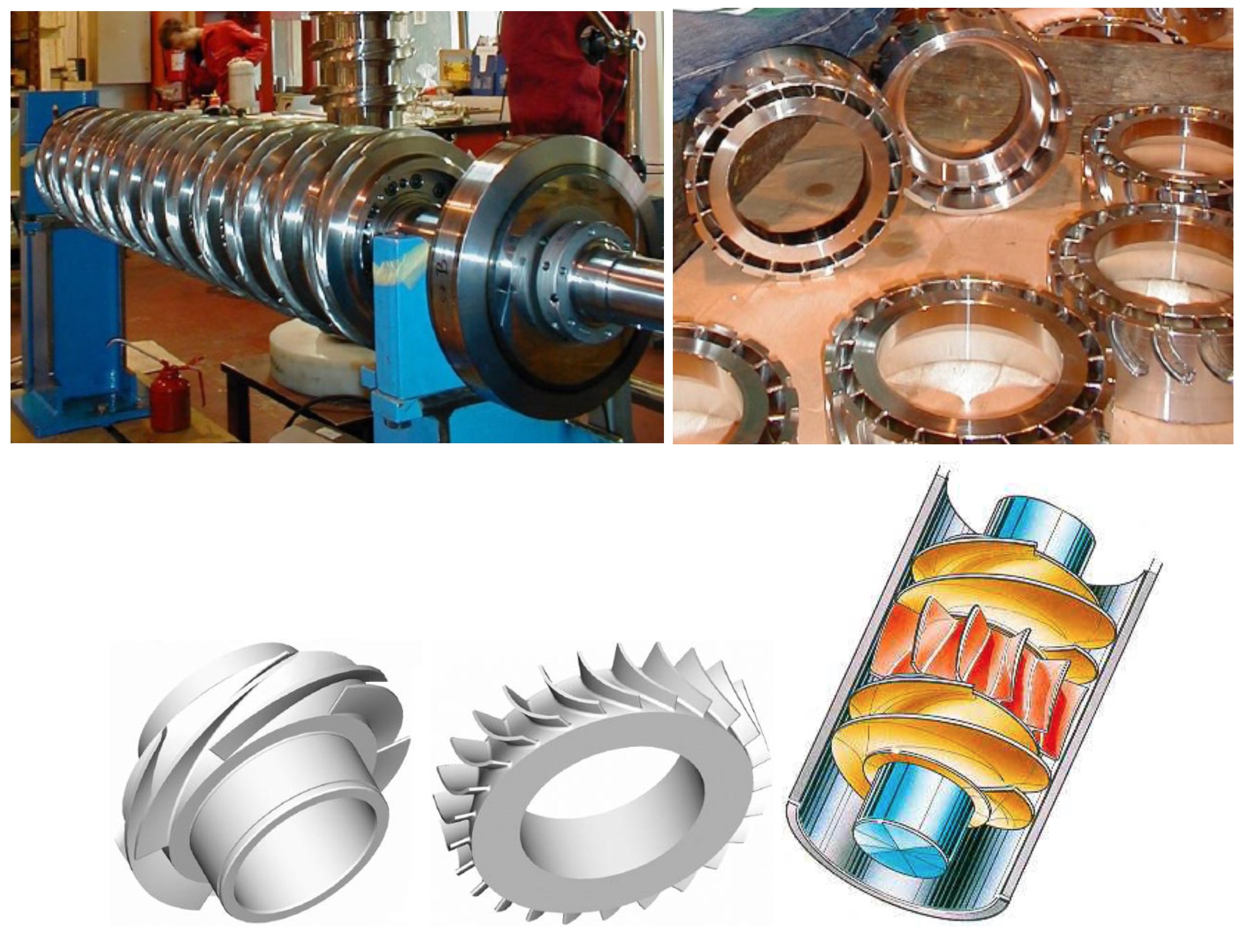
The gas volumetric flowrate is reduced during the compression of the multiphase mixture, as in compressors, and the design of the stages is adjusted every three, four or five stages to provide the best performance. Multiphase pumps deliver a head. Differential pressures between suction and discharge depend on multiphase mixture densities. Within some limits, the pump can adjust itself to variations of pressure resulting from gas fraction variations.
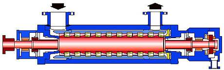
The layout is a multistage barrel in-line pump with axially split inner casing (see Figure 8.2, “MPP Mechanical Design”).
The shaft sealing is achieved with mechanical seals. In order to avoid gas or solid particles contaminating the faces and also to allow for dry running conditions, a pressurised external fluid is injected into the seal. Between the seal fluid circuit and the suction/discharge nozzle an overpressure (e.g. 5bars) is continuously maintained.
Operating conditions often dictate the need for materials that possess excellent corrosion and erosion resistance:
Corrosion: effluent may contain hydrogen sulphides with water and chlorides, sometimes combined with high temperatures.
Erosion: sand may be entrained by the effluent.
Therefore, in order to cater for aggressive effluents of this nature, all parts in contact with the fluid would usually be in duplex stainless steel or super duplex stainless steel.
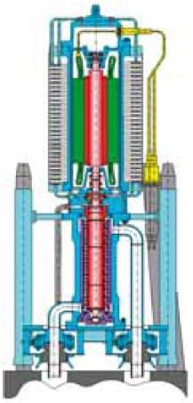
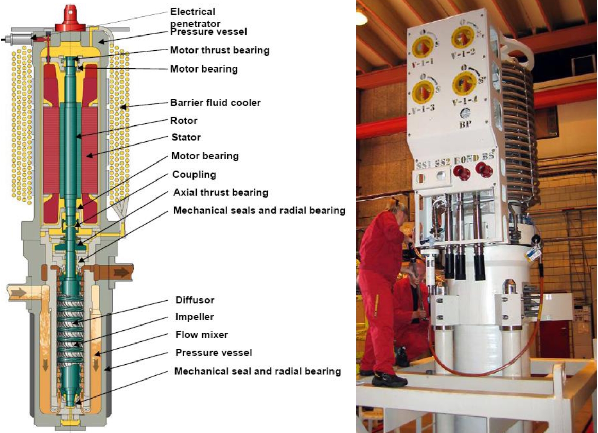
The Subsea MPP can be either electrically, or hydraulically driven (Figure 8.3, “Hydraulic Driven MPP (Sulzer)” and Figure 8.4, “Electric Driven MPP (Sulzer)”).

The main advantages of the helico-axial technology are:
Ability to pump any GVF from 0 (100% liquid) to 1.0 (100% gas)
Mechanical simplicity and reliability (one single shaft, rotodynamic principle)
Compactness
Self-adaptation to flow changes
Very tolerant to solid particles (open type axial impeller, without tight clearances)
8.2.3 MPP state of the art of the subsea industry
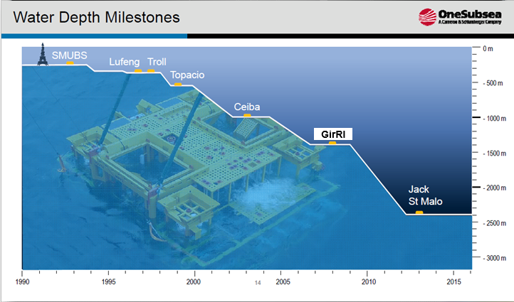
Following figures provided by OneSubsea (now Schlumberger) provide an overview of technology capacity evolution since early stage of development of Subsea Multiphase Pumping.
8.2.4 MPP state of the Art at TOTAL
TOTAL has today four installations involving subsea pumping (see figure below) and made three World First:
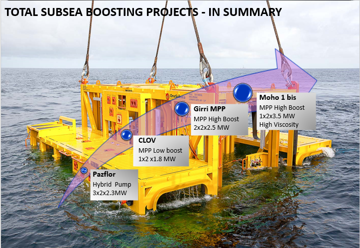
On the above figure, the first number designates the number of MPP stations installed, the second number designates number of subsea pump(s) installed on each MPP stations (2 subsea pumps installed on each MPP station for the four TOTAL applications) and last number designated the nominal power of each pump).
8.2.5 Main MPP systems manufacturers
The main MPP systems manufacturers are the following:
ONESUBSEA (formerly FRAMO), a 100% Schlumberger-owned Company. OSS is developing the whole Subsea Pumping System (SPS).
TechnipFMC - SULZER. Sulzer is providing the motopump only and is associated with TechnipFMC to deliver the whole Subsea Pumping systems.
AKERSOLUTIONS (AKS). Alike OSS, AKS is developing the whole MPP system.
BHGE (part of GE). A new comer who is working on a very innovative MPP solution.
All these four MPP manufacturers propose Rotordynamic pumps. There is no Suppliers today working on subsea Twin-Screw MPP even in the past different consortium like Aker Kvaerner – Bornemann and Leistritz – Curtiss-Wright have worked on it.
8.2.5.1 ONESUBSEA (OSS)
OSS has a strong position of Leadership with:
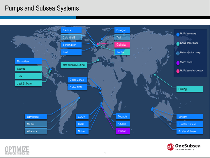
More than 30 projects executed (see figure below).
More than 100 subsea pumps delivered.
Cumulative operating time > 350 years (3 million hours).
Pump reliability MTTF > 35 years.
Qualified technology for standard and high boost
OSS Pumps operating range is as follow:
As can be seen above, the MPP technology of OSS is based on the Helicoaxial hydraulic developed by TOTAL, IFP, STATOIL, through the Poseidon program launched in 1984.
OSS Pumps technologies is as follow (Fig.8). As can be seen, it covers the full range of GVF.
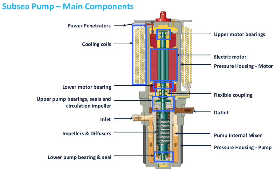
Typical design of a OSS subsea pump is as follow:
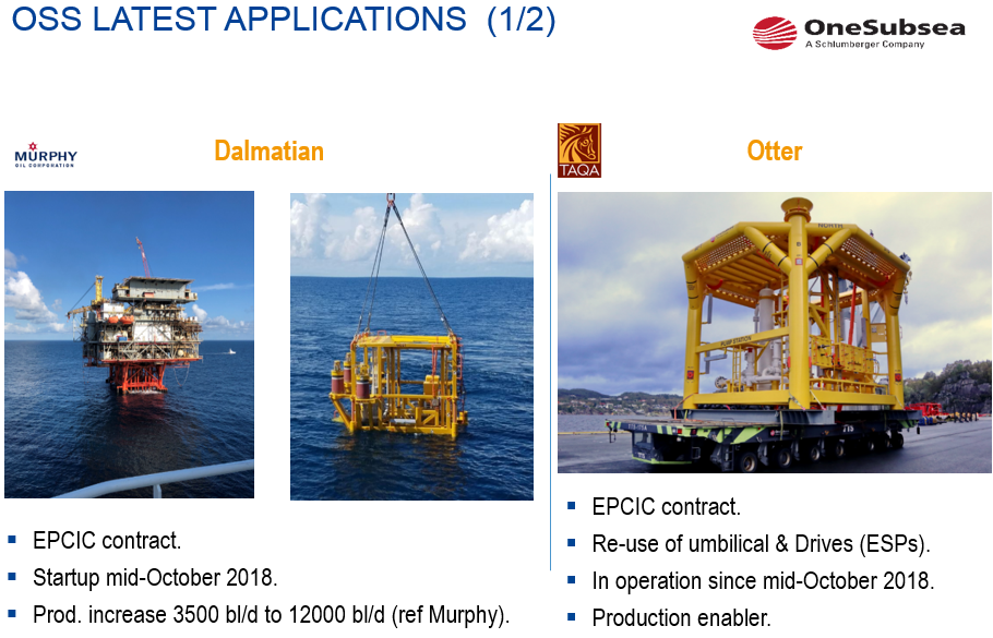
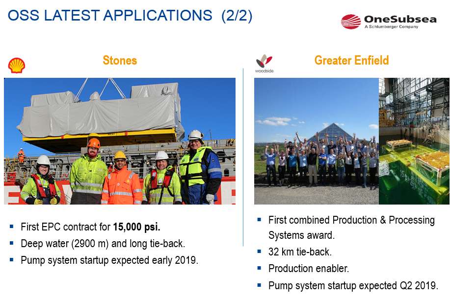
OSS latest applications are as follow:

8.2.5.2 TechnipFMC / Sulzer
Alike OSS, the MPP technology of SULZER is based on the Helicoaxial hydraulic developed by TOTAL, IFP and STATOIL through the Poseidon program launched in 1984.
However, unlike OSS, SULZER is using a synchronous liquid-filled motor based on a permanent magnet rotor. This technology allows having a liquid-filled motor running at 6000rpm with good efficiency.
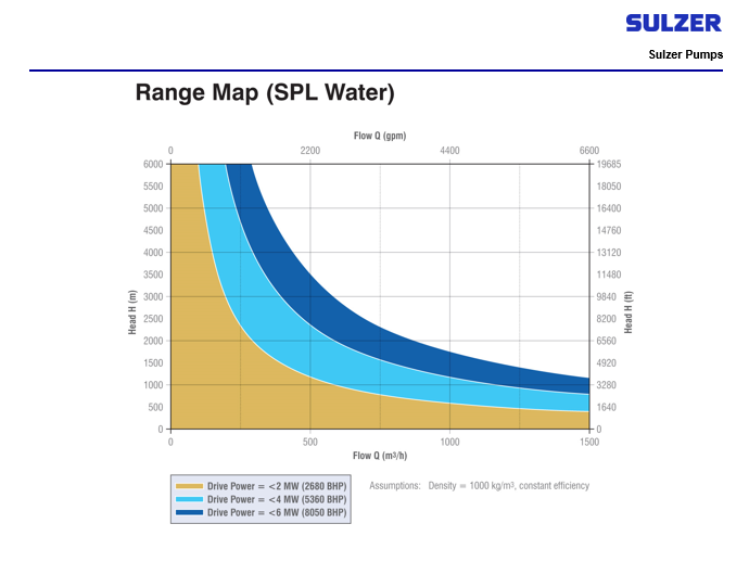
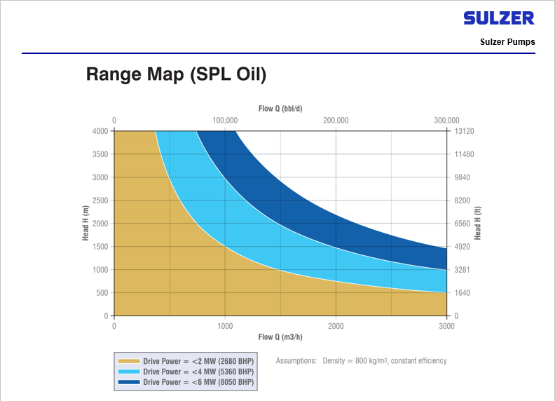
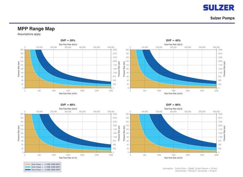
Sulzer Pumps technologies and range maps are as follow. As can be seen it covers full range of GVF.
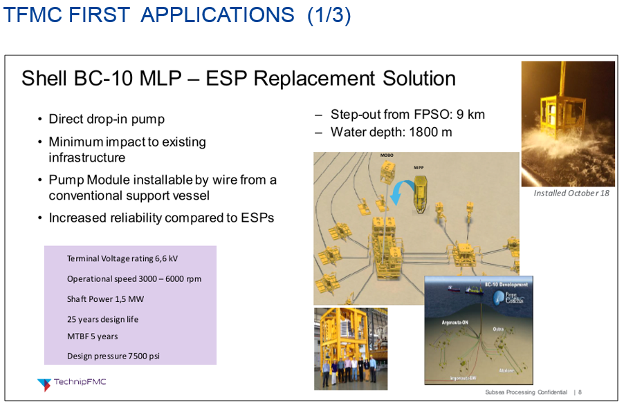
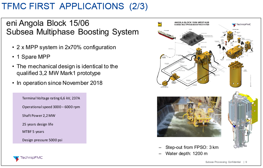
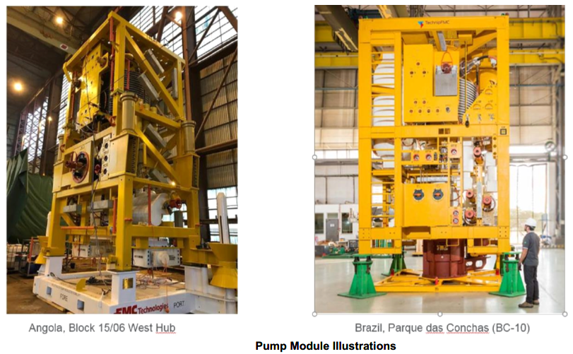
Sulzer / TFMC Existing applications:
Start-up of BC-10 subsea pump has been performed end of 2018. Second award for FMC subsea multiphase boosting system was for Eni Angola's Block 15/06 West Hub Development Project.
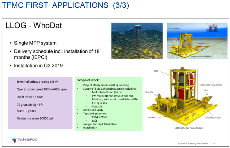
Sulzer / TFMC application to come:

8.2.5.3 AKERSOLUTIONS (AKSO)
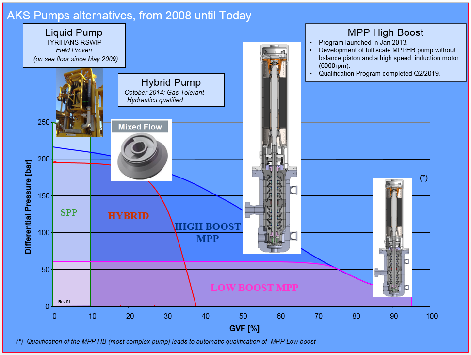
In 2010, AKSO stopped the collaboration they had with Bornemann to develop subsea Twin-Screw Multiphase Pumps, and decided to develop their own product. In 2012, they launched a JIP program, in which TOTAL took part, to develop a new multiphase pump technology, i.e. to take up the four following challenges:
To develop a “Non Poseidon” multiphase impeller.
To develop a MPP with impellers in back-to-back configuration.
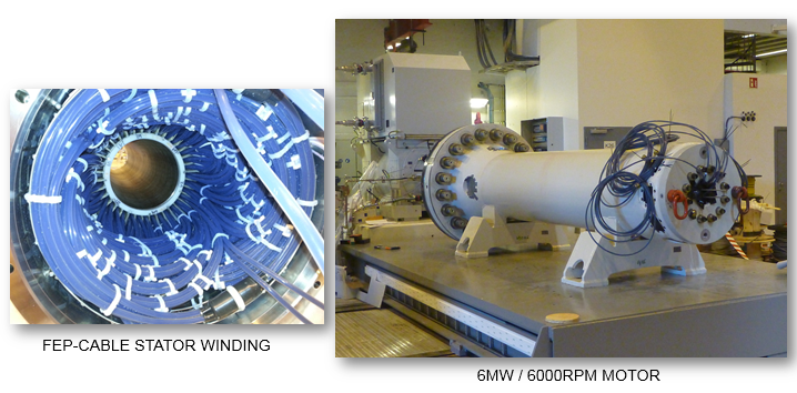
To develop a High Speed (6000rpm) / High Power (6MW) induction liquid-filled motor.
To develop a new stator winding insulation cable.
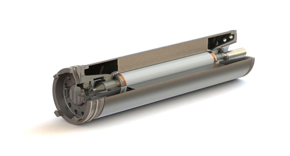
Unlike OSS and Sulzer, AKSO MPP is based on close semi-axial impeller, with an outlet angle of ~45°.
AKSO MPP (called MultiBooster) is also the first MPP with impellers in back-to back arrangement. That allows avoiding the use of a balance piston to compensate the axial thrust.
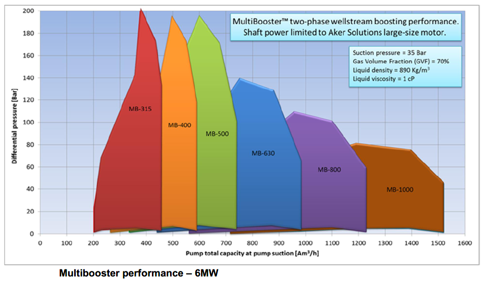
AKSO strategy being to be a full Pumping System Supplier, they had to develop both the MPP and the motor. They thus developed a 6MW / 6000-rpm liquid-filled induction motor.
For the proper operation of the motor, AKSO had to develop a new stator winding cable. Traditional XLPE winding insulation is limited to 70°C of operating temperature (class Y/90°C max Temp), and to meet such limit, a high-speed induction liquid-filled motor would need an extreme big cooler. The solution has been to qualify a new motor winding cable, i.e. a FEP (Teflon) cable class H/180°C max Temp.
Status on AKSO MPP Development / Qualification
At Q1/2019, the motopump system has cumulated 1’700 operating hours and passed successfully all qualification tests. The motopump system should totally complete the Qualification Program in Q2/2019, and will be then ready for commercial use.
AKSO will then be the third MPP System Supplier on the market, with the following Portfolio:
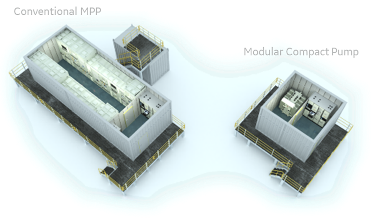
8.2.5.4 BHGE MCP (Modular Compact Pump)
Challenges brought by Ultra Deep and Long Tieback applications are not currently solved by conventional systems.
For these projects to come, the biggest challenge to address is the ability to generate high DP (high Head). For a Rotordynamic pump, generating Head requires high speed, or more Head per stage, or more stages. With existing pump designs with 13 impellers, we can today generate a DP of 210bar at 60% GVF. However, this is almost the starting point for long tieback and ultra-deep projects.
Removing the barrier fluid system is the second challenge to address. Tiebacks are getting longer, meaning that the cost of an umbilical carrying all the hydraulic functions becomes unacceptable. DP is getting greater, meaning that the barrier fluid pressure becomes more and more complex to control. For example, if the MPP is generating a DP of 220bar, with 2/3 of the DP used to decrease the suction pressure and 1/3 used to increase the discharge pressure, then during a pump trip, the suction pressure (to where the barrier fluid is usefully referred to), will immediately increase by 147 bar.
The Modular Compact Pump (MCP) is a barrier fluid-less pump, based on an entirely new subsea pump architecture, which enables flexible high boost solutions. The MCP is inherently different from a conventional pump by not having a motor in one end, driving a long rotating shaft, but rather having a separate permanent magnet motor integrated with each impeller, and the impellers rotating around a static shaft. The fact that there is no rotating shaft eliminates the rotor-dynamic challenges of a conventional pump. This also enables a canned motor, removing the need for a mechanical seal around the rotating shaft, a component that always affects reliability of any rotating equipment. Therefore, the pump has no barrier fluid system driving size & complexity of the umbilical and topside equipment, as illustrated by Figure 8.30, “Typical topside equipment needed for a conventional MPP system versus the MCP”. It also notably simplifies the umbilical design, significantly reducing the system cost. This makes the MCP a true all-electric subsea pump, aligning well with all-electric subsea production systems currently being developed.
With the design of the pump inherently modular, it can meet the fields’ boosting requirements by simply choosing the right number of standardized identical stages, without any rotor dynamic limitations.
Figure 8.31, “View of the MCP modular concept” shows how stages can be added to achieve very high boosting with a single pump. In theory, unlimited boost can be achieved.
The MCP concept relies on advanced process lubricated bearings. Each impeller holds its own journal and thrust bearings, meaning that each impeller handles its own axial thrust. This approach optimizes the chance of using process-lubricated bearings as it limits as much as possible the axial thrust applied on the bearings.
BHGE / MCP Development Phasing
Phase 1 consisted to build a 3-stage prototype to verify and validate the concept. This phase was successfully achieved in December 2017.
Phase 2 immediately followed and was a 1-year program consisting to further run qualification tests to de-risk the key components (Product-Lubricated bearings, motor stator can, penetrators, VSD). The Phase 2 is ongoing and should be finished Q2/2019.
Phase 3 should start in Q3/2019 and will consist to build a full-scale 1MW module of 4 stages.

8.3 Twin Screw Pumping System
There is no Suppliers today working on subsea Twin-Screw MPP even in the past different consortium like Aker Kvaerner – Bornemann and Leistritz – Curtiss-Wright have worked on it.
8.3.1 General
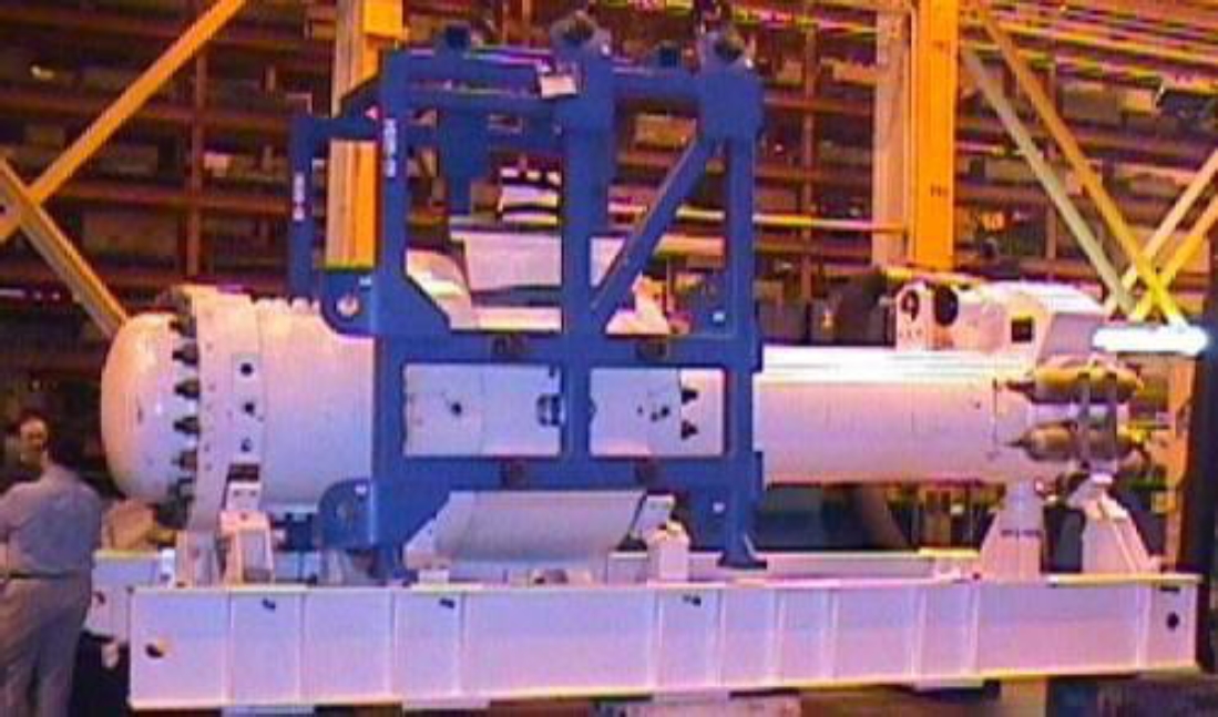
Curtiss-Wright Electro-Mechanical Corporation (CW-EMD, former Westinghouse) was marketing the "Wellamps" system based on the Leistritz twin screw multiphase pumping and developed in the frame of Petrobras SBMS-500 project, which stands in Portugese for Subsea Multiphase Pumping System – 500m3/h total flowrate.
Aker Kvaerner has developed and installed a multiphase pumping system ("MultiBooster") based on the Bornemann's twin screw pump. The Bornmann positive displacement pump has numerous onshore and offshore references in oil and gas multiphase pumping and Aker Kvaener obtained a worldwide licence for subsea applications.
8.3.2 Technical Description
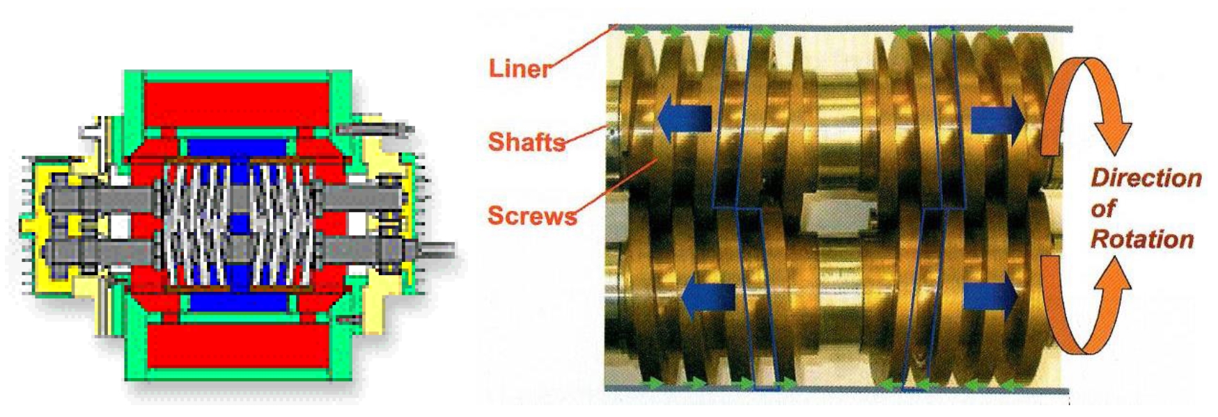
The technology is based on a pumping of the fluid by reverse rotating screws, which enclose it in sealed serially acting chambers and hence provide the axial motion (see Figure 8.32, “Twin Screw Pump Principle”).
It allows handling of solids up to 10mm and high gas fractions. However, it requires the presence of some liquid (i.e. a GVF up to around 95%) to generate sealing between the screws and the inner casing.
It avoids emulsion formation due to the axial motion and low shear conditions applied by the twin screws, which work at relatively low speed compared to the helico-axial technology used in combination with specifically designed impellers (refer to Section Section 8.2, “Multiphase Helico-Axial Pumps”).
The system is proposed in different sizes capable to handle 75,000 – 300,000 bbl/d (i.e. up to 2,000m3/h).
The Aker Kvaerner MultiBooster system is fed through a service umbilical and hence supplied in hydraulics, power, chemicals, communication and pump barrier fluid for lubrication, cooling and pressure/volume compensation.
The pump and motor are contained in common pressure housing. They are separated by a mechanical seal, but the same lubricating fluid fills the housing. The internal pressure is regulated and kept around 10bar higher than in the pump in order to ensure that no intrusion in the motor of water or hydrocarbon will occur. The lubricating oil is continuously supplied through one line of the umbilical.
8.3.3 Field Track Record
The Aker Kvaerner track record is the following:
The Aker Kvaerner MultiBooster system has been installed on the Canadian Natural Resources (CNR) Lyell field at 145m water depth in December 2005.
It allows for boosting of 150kbbl/d of produced fluids from 10bar to 28bar for the 15km long transportation to the Ninian South platform. It is fed by a 1.1MW variable speed drive power supply on the Ninian north platform through a high voltage 180mm diameter power and control umbilical (Duco).
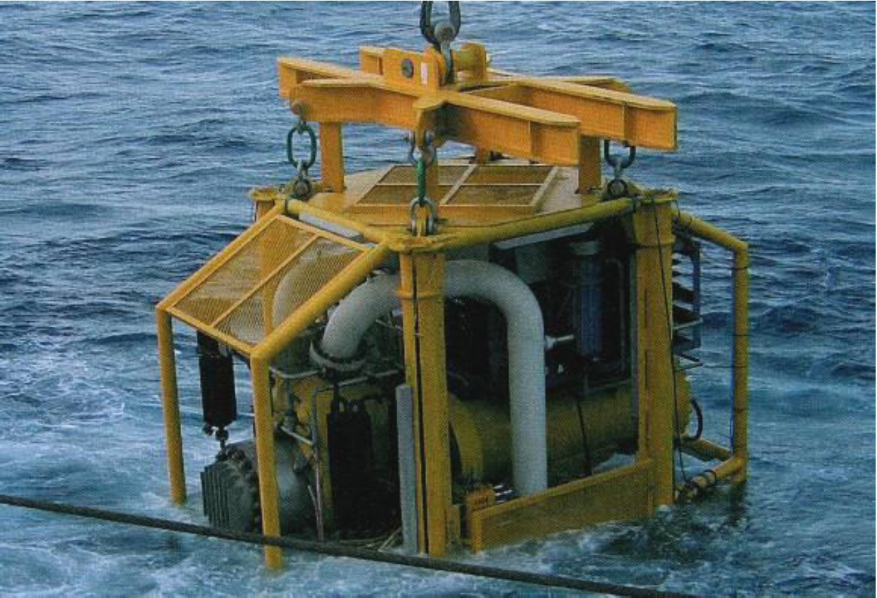
The pump module weighs around 50T and measures 5.4m x 3.1m x 5 high.
The use of the MultiBooster on Lyell is seen as a pilot (while "real" application begins with the King field, see below). The expected time between failures is around three years. Maintenance requires the complete module to be retrieved.
The pump only operated 11 months after its initial installation.
The system was also installed on the BP King field in the Gulf of Mexico (2007) in up to 1700m of water. The electrically driven pump modules (2 off plus one spare) were connected to the Marlin platform through a power umbilical. It boosted the production from three wells in the King field.
These pumps began operating in November 2007, and ceased operating in February 2009 due to “operational issues”.
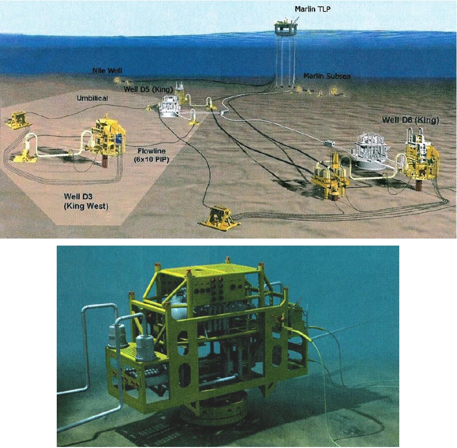
The Bornemann pumps to be used on BP King are MPC-335-50s, which will deliver up to 50 bar differential pressure and 75,000bbl/d. The gas fraction of the King field light crude oil could reach 70%.
Each module (including pump module and manifold base skid) weighs around 70T and measures 9.1m x 3.7m x 6.8m high. They will be installed onto 3.6m diameter, 23.5m long suction piles.
For maintenance operations, the subsea control module and pressure regulator can be retrieved separately. A major failure problem would require to pull-out the whole module and to use the spare MultiBooster pump.
The Curtis Wright EMD / Leistritz Wellamps track record is the following:
The SBMS-500 system has been developed under a JIP coordinated by PETROBRAS and Curtiss-Wright (including also BP, Marathon and Chevron Texaco). It has been installed on the Marlim field P-20 platform in around 900m water depth in mid-2008 for test.
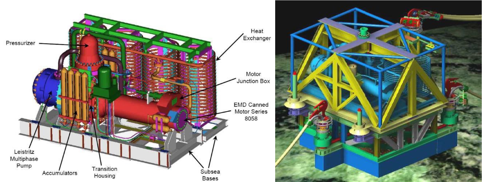
The system characteristics are the followings:
Total flowrate: 500 m3/h
Differential Pressure: 60bar
Gas Volume Fraction: up to 95%
Power: 1.3 MW (1700 hp)
Motor Voltage: 6.7 kV
The system weighs around 51T. Its dimensions are 5.8m x 4m x 3.7m high.


