
5 Gas / Liquid Separation
5.1 General
The gas/liquid separation allows for transportation of single phase fluid, with the advantages of reducing both the pressure drop and the slug issues.
The Gas/Liquid separation can be used to ensure a hydrate strategy (separation of gas from liquids), to allow for a single phase boosting or both. A single liquid phase can be more easily boosted, e.g. by means of electrical subsea pump, with the aim of benefiting of one or several of the following advantages:
increase the well flowrates (i.e. higher production rate)
decrease the well abandonment pressure (i.e. longer field life / recovery rate)
Increase the transportation distance for deepwater fields or satellite accumulations development
The separation can be based on different methods, including:
Dummy well / VASPS type
Gravity (horizontal or vertical) separators
CDS Engineering / Statoil in-line degasser
5.2 Separation Technologies
5.2.1 Dummy Well / VASPS
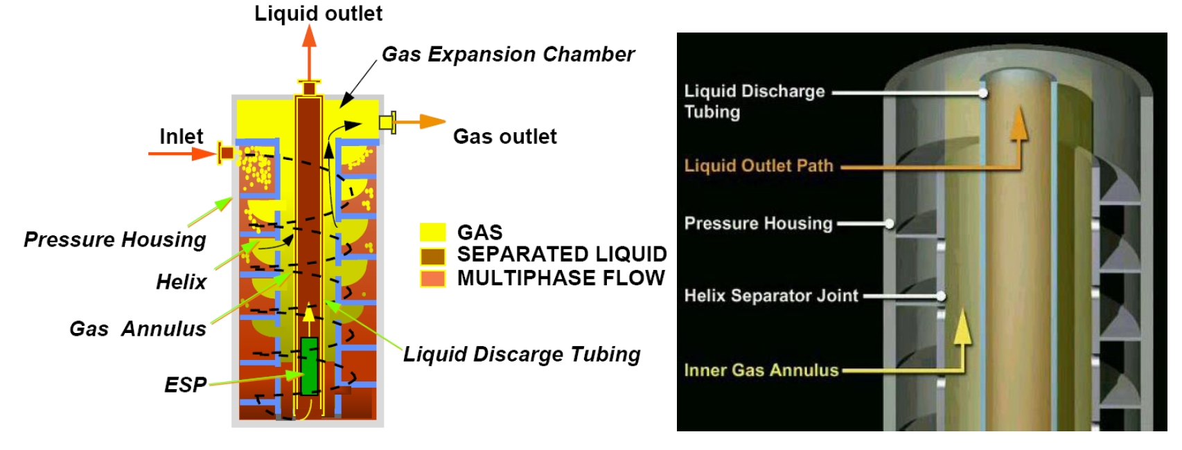
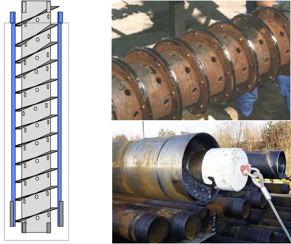
The VASPS separation system consists of a vertical separation system located in a dummy well. It basically consists in an annular helix, which separates the gas/liquid phases by centrifugal forces.
Refer to the following Section 5.3, “VASPS” for further details.
5.2.2 Gravity Separator
The gravity separator is the most common separation principle found in topside applications. The separation principle is based on the motive force of the gravity and the different densities of the fluid components. Refer to Section 3.2.1, “Gravity Separator” for further details.
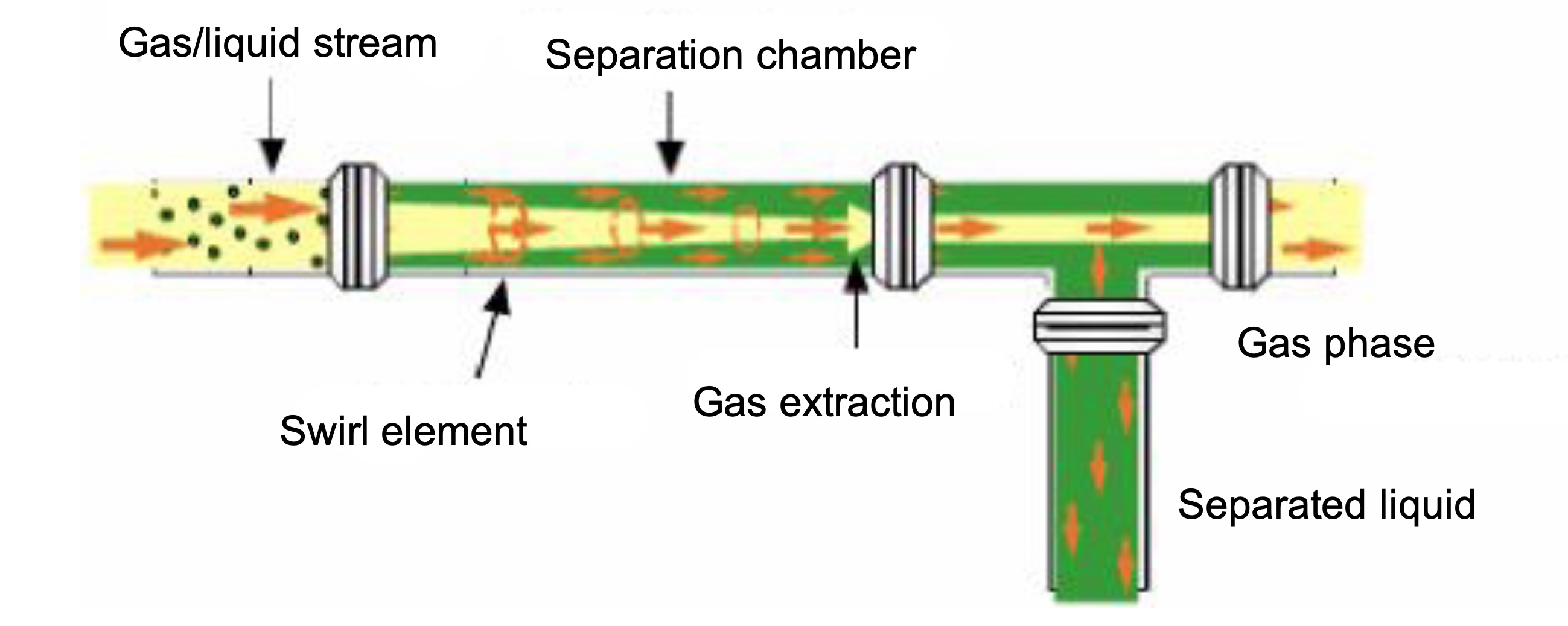
5.2.3 In-Line Separator
The In-line cyclonic separation technology is developed with the incentive for compact and efficient separation. It is based on the principle of high centrifugal force generated by swirling flow.
Such systems have been developed (Statoil ASA / CDS Engineering - Refer to Section 3.2.2, “In-Line Separator”) and several types of in-line separator systems have been successfully put in operation topside, including Statfjord B, Sleipner T and ETAP in the North sea. An important drawback of this technology is that stabilized flowrate is required thus limiting the subsea application of this technology.
The following Figure 5.1, “In-line Gas/Liquid Cyclonic Separator Schematic” depicts a schematic of an In-line gas/liquid separator.
5.3 VASPS
The Vertical Annular Separation and Pumping System (VASPS) is a two phase (gas/liquid) separation system. It has been installed by Petrobras in 2001 on the Marimba field in 400 m WD with a tie back to the P8 platform.
5.3.1 The Separation Principle
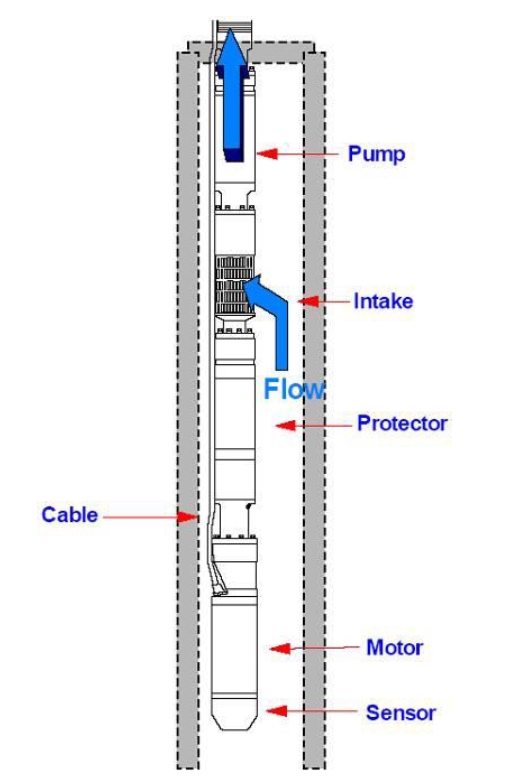
The VASPS separation system principle is described in the Figure 5.2, “The Vertical Annular Separation (VASP) Concept” below. The fluid is forced into the system annular helix, which separates the gas/liquid phases by centrifugal forces. The gas is allowed to exit the annular through holes regularly dispatched and exits the separator by a dedicated outlet located at the top. The liquid phase concentrates in the bottom part of the separator and is pumped by the ESP through a central tube.
5.3.2 Project Description
The VASP project has been phased as follows:
Phase 1 - 1990-91 - Lab tests with air and water
Phase 2 - 1993-95 - In-land field tests at AGIP site test in Trecate-Italy
Pre-subsea Phase - 1995-97 - In-land field test at PETROBRAS site test in Atalaia-Brazil
Subsea Demonstration Phase -1998-2002 in Campos Basin
Production Phase (Marimba field) – 2002 up to 2008 with well failure and with ESP replacement in 2004.
The VASPS system was initially started-up in July 2001 and produced until November 2001 when an incident occurred. The ESP lost pumping capacity during a re-start operation due to a closed surface valve, which forced the ESP to run under shut-off condition during 13 minutes. The defective ESP was replaced.
The system is used on the Marimba field for the "Operation" phase of the project since 2002 at a water depth of 400m. The ESP was retrieved and replaced by a new unit in January 2004, with some extra robustness included (e.g. in the control system). From 2005 until 2008, VASPS operated well until well failure.
The system design data are the followings:
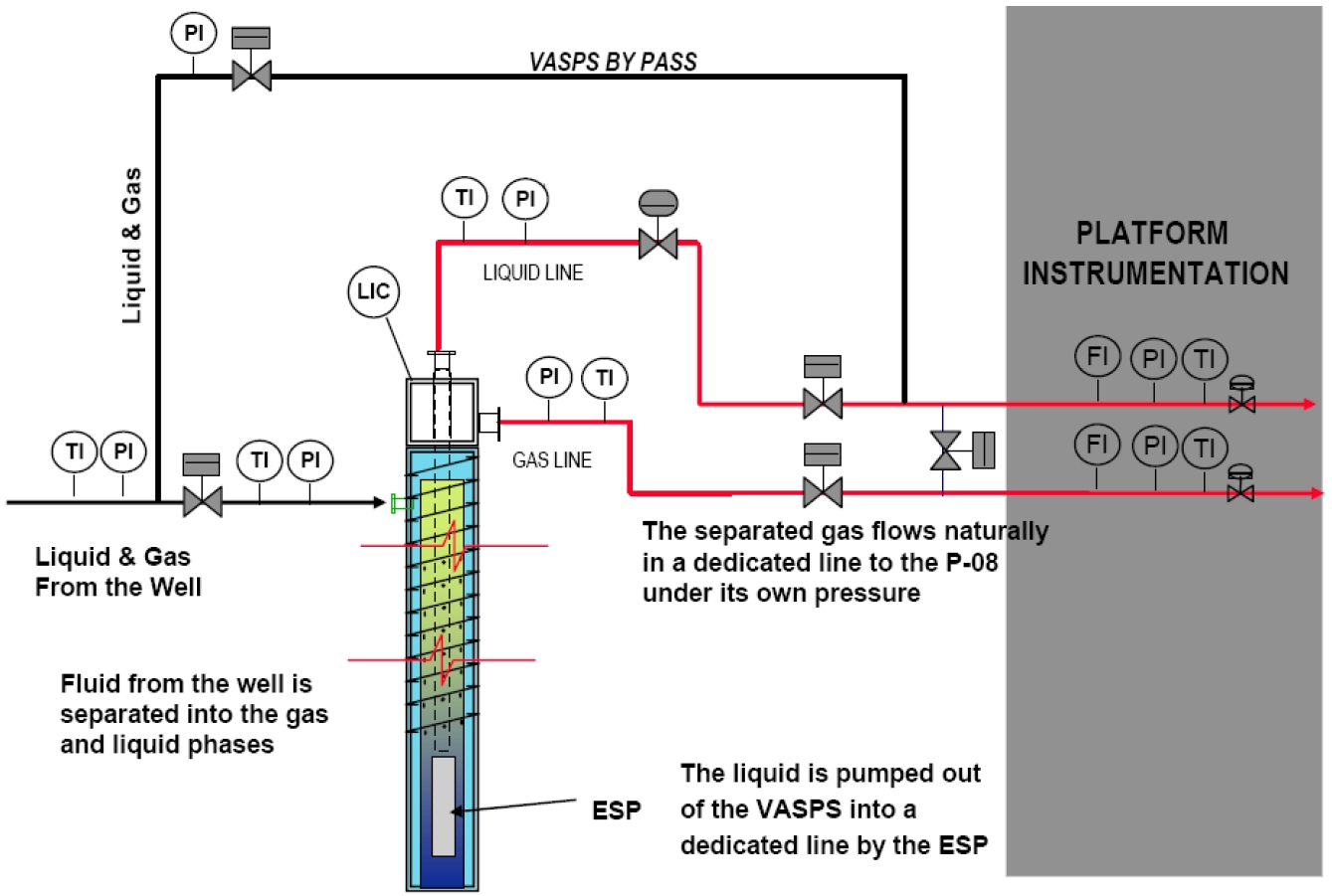
The system process is described in the Figure 5.3, “Marimba VASPS System Process” below. A production flowline feeds the VASPS system with mixed fluid (550m long line between well and VASPS). Two dedicated lines allow transferring both the separated gas (under its own pressure) and liquid (boosted by the ESP) to the platform. A by-pass system allows direct transfer between the well and the P8 platform (e.g. for VASPS system maintenance).
5.3.3 VASPS System Description
The main components of the VASPS system (and their suppliers) are the followings:
Subsea Hardware (Cameron – England)
Control system (Kongsberg – Norway)
ESP (Reda –USA), Variable Speed Driver (Robicon –USA)
Level Sensor (Khroner – Germany / Tecnomare – Italy)

The Figure 5.4, “System Overview” depicts the overall system. Each of the components is detailed below.
The system is installed within a dummy well and requires only conventional drilling and completion technology for installation and maintenance.
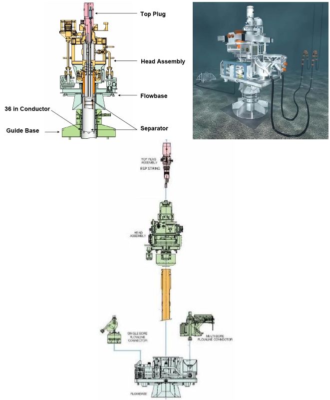
Subsea Hardware
The subsea hardware includes the connecting systems, valves, sensors and control systems.
The flowlines and umbilical subsea connections are made on the flow-base tree.
The head assembly includes the main piping (from the separator) and valves.
The top plug is a multipurpose component derived from the Spool Tree Tubing Hanger concept:
Supports the ESP system
Interface for installation of the system / maintenance
Carries the Level Sensors, which allow monitoring the liquid/gas level in the system.
The guide base makes the interface with the dummy well and seabed.
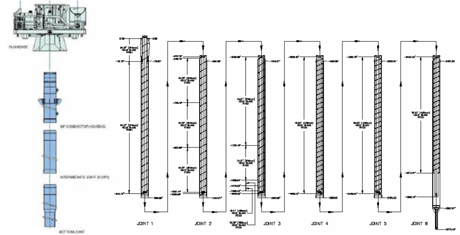
The Separator
The VASPS separator is composed of 6 joints, featuring each a 12m length and a diameter of 26”, and assembled by means of Merlin connectors.
The Electrical Subsea Pump is composed of the following main elements:
Electrical motor REDA 390 HP , 2765Volts , 60 Amperes
Protector REDA LSBPB – series 540
Pump REDA SN8500 - 73 stages
Penetrator, jumper, umbilical connector TRONIC
Variable speed driver (VSD) ROBICON
Multisensor PHOENIX
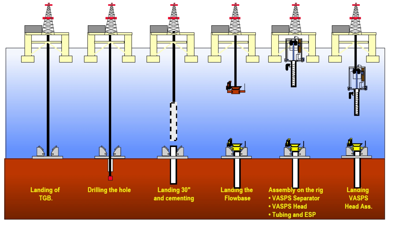
5.3.4 VASPS System Installation
The installation of the VASPS system has been performed by the drilling rig SEDCO 710 (Petrobras SS-43). The operation took 7 days and includes the following main steps:
Drilling of the dummy well
Lowering of the casing and cementing
Installation of the flowbase
Assembling of the VASPS separator (pressure housing and helix)
Connection of the head assembly to separator
Assemble the ESP, still well and top plug
Pressure test of the system
Lower the complete set to the seabed
Lock onto the flowbase
The Figure 5.9, “VASPS System Installation” summarises the main steps of the VASPS system installation.
5.4 Shell's BC-10 and Perdido Projects
Shell has awarded FMC two full-field development contracts utilizing subsea oil and gas separation and boosting systems: the BC-10 field development (Brazil) and the Perdido Regional Development project (GoM).
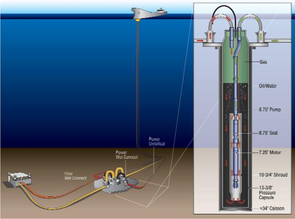
Both fields use subsea stations based on ESPs located in vertical caissons (see Figure 5.10, “The subsea separation caissons with their ESPs” below). The path of the stream into the caisson produces a cyclonic separation of the gas from the fluids, also helped by the gravity. The gas flows through one line to the surface facilities. Electric-submersible-pumps (ESP) boost the oil-water mix up to the platform.
5.4.1 BC-10 Project
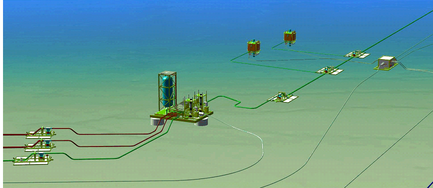
The BC-10 block is located 120 km southeast of the city of Vitoria (Brazil) in water depths ranging from 1,500m to 2,000m. It is a two-phase project, with the first step developing three fields (Ostra, Abalone and Argonauta), the second phase a fourth field (Nautilus), third phases two additional fields (Massa and O-South)
The development is based on a FPSO with capacity for 100,000b/d of oil capacity and 75,000b/d of water injection. BC-10 is the first full field development based on subsea oil and gas separation and subsea pumping. Phase 2 came onstream in October 2013. It uses six high power ESP vertical booster stations (Centrilift). Four of the systems include liquid/gas separators (see Figure 5.10, “The subsea separation caissons with their ESPs”). The other two do not include separators but employ specially-designed Centrilift multi-phase fluid pumps.
Some ESP pumps have been replaced by the installation of one MPP station delivered by TechnipFMC (Sulzer multiphase pump technology).
5.4.2 Perdido Project
Perdido Regional Development project (Great White, GoM) is located approximately 320km south of Freeport (Texas). It started in 2010.
The field development features a spar moored in about 2440m of water, making it the deepest production spar in the world (???). It produces from three fields, Great White being the flagship field and covering more than six blocks in water depths from 2,300m to 2,900 m.
Production from the different fields tie back to a central separation and boosting station located below the spar. Two main factors leaded to the requirement for a subsea separation and boosting system on the field:
the relatively low pressure and temperature characteristics of the wells, which magnifies the hydrate formation issues.
The ultra-deepwater development leads the produced fluid to face a 2450m of fluid head pressure at riser bottom, hence calling for an active lifting system.
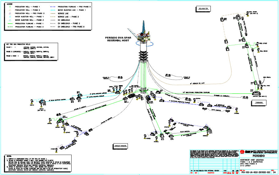
Shell has awarded FMC Technologies the contract for the subsea equipment, including five subsea caisson separation and boosting systems. Production from the fields is commingled in 92m long caissons, using cyclonic effect and gravity to separate the gas from the liquids. The gas flows through one line to the surface facilities. Electric-submersible-pumps (ESP, Centrilift) boost the oil-water mix up to the platform.
Study is on-going for Perdido field regarding different options for ESP replacement.
5.5 Pazflor Project
Pazflor is a Total project offshore Angola, which features (gas/liquid) subsea separation. First oil started in 2011.
![[Tip]](tip.png) | Tip Click these links below for access to 3D resources: |
The project encompasses two types of development:
Oligocene reservoir: a "conventional" West of Africa scheme based on production loop and clustered wells.
Miocene reservoirs, featuring heavy 17-22° API oil and low energy reservoirs, which require artificial lift for development. The Pazflor Miocene reservoirs development is based on subsea separation and boosting performed at the extremity of each of three single flowlines (FPSO location) on which the production wells are tied through in-line tees. The hydrate prevention strategy is based on the flowline depressurisation through the gas lines and risers.
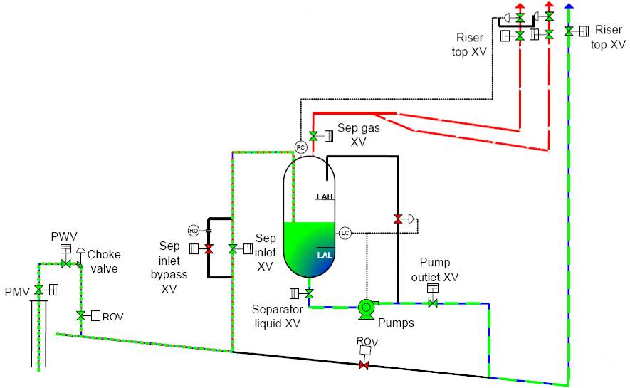
Each Subsea Separation Unit (SSU) is fed by a 10" single production flowline. The gas and liquids (i.e. mixed oil/water) are separated and transported to the floater through respectively two 6" gas lines/risers and a 10" liquid line/riser fitted with a subsea pump. An SSU consists of:
Foundation and structure
Separator module
Manifold (s) with valves & piping module
Pumps modules
Power / Control Umbilical
Subsea Control Module
The subsea separation has been selected for the following technical and cost benefits:
The separation of gas from the liquids allow for avoidance of hydrate formation and for a stabilised flow regime in the risers.
The subsea boosting of the liquid phase alone is more efficient than use of multiphase gas/liquids pump.
Positive impacts on the topsides, as follows:
low requirements for topside gas compression, due to the absence of gas lift system
No dead oil circulation during shutdown, implying saving on topside pumps and heaters
Reduced first stage separators
CAPEX saving due to the subsea architecture based on single production flowline scheme: optimised drilling trajectories (daisy chain configuration versus manifolds), no manifolds, fewer spool pieces, no pigging loops, reduced insulation requirements, less stringent cool-down requirements, etc.
Due to the Pazflor project innovative aspects, the following critical issues were studied in details through a qualification program:
Subsea pump design
Cold restart
Sand management


