3 PLATFORMS & FLOATERS OVERVIEW
3.1 Introduction
A floating structure for hydrocarbon drilling, production and export typically has the following performance requirements:
Sufficient work area and deck load capacity.
Storage capacity, as the case may be.
Dry trees suitability (or wet trees) depending on reservoir geometry & characteristics.
Tolerance to topside late changes, weight increase, fabrication eccentricity, process de- bottlenecking.
Acceptable response to environmental loads, e.g. wave induced motions.
Adequate stability (e.g. topside process).
Strength to resist extreme conditions.
Durability to resist fatigue loading.
May require a combined function (e.g. drilling and production).
May be transportable.
No one structure type can provide optimum performance with regard to each of the above requirements. Thus, any field development or exploration activity should identify the optimal structure type for the particular task from a number of classes of floating offshore structures. For example, excellent stability characteristics may lead to excessive motions in waves. In response to these conflicting requirements, the offshore industry has developed a wide variety of platforms.
3.2 Fixed Platforms
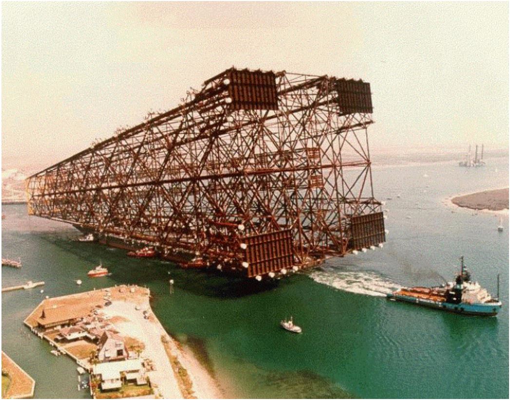
A fixed platform consists of a welded tubular steel jacket, deck, and surface facility. A jacket is a tubular supporting structure for an offshore platform consisting of four, six, or eight 2m to 4m diameter tubular welded together with pipe braces to form a stool-like structure (see Figure 3.1, “Shell’s Bullwinkle Platform under tow to installation site”). The jacket is secured to the seafloor by its weight and typical 2m diameter piles that penetrate up to several hundreds of meters beneath the mud-line. Skirts are also added for fixing the jacket to the seafloor.
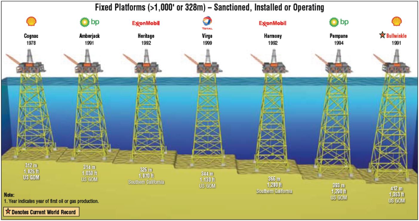
Fixed platforms are preferable to floating production systems for large fields and in small-medium water depths, e.g. < 400m. The long term lower operating costs and probably better reliability compensate for the possibly greater initial costs and time to first oil. When oil storage is required then a gravity platform or jacket plus FSO may be used.
However, for deep water (greater than 400m) or more marginal fields (i.e. field life less than perhaps 10 years) the fixed platform is not economic, and the FPU would be the preferred solution.
The following Figure presents the fixed platforms installed in deepwater up to 400 meters approximately.
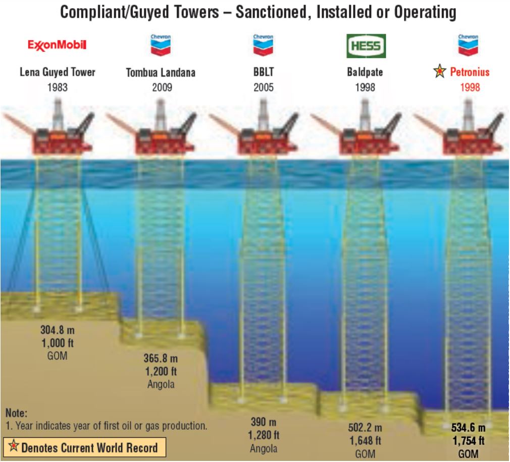
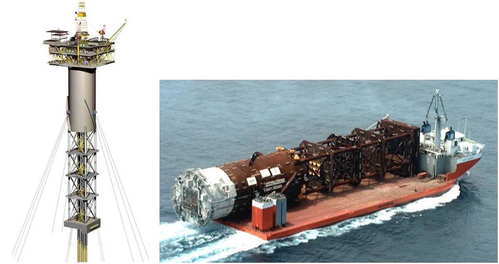
3.3 Compliant Towers
Compliant towers are similar to fixed platforms in that they have a steel tubular jacket that is used to support the surface facilities. Unlike fixed platforms, compliant towers yield to the water and wind movements in a manner similar to floating structures due to their compliance. Like fixed platforms, they are secured to the seafloor with piles. The jacket of a compliant tower has longer dimensions than those of a fixed platform and may consist of two or more prefabricated sections that are assembled. It can also have buoyant sections in the upper jacket with mooring lines from jacket to seafloor (i.e. guyed-tower designs) or a combination of the two. These differences allow the use of compliant towers in water depths approaching the 1000meters mark. This range is generally considered to be beyond the economic limit for fixed jacket-type platforms. The following Figure presents the Balpate Compliant Tower at the fabrication yard.
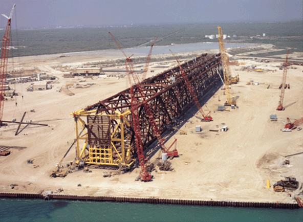
Large barge-mounted cranes position and secure the jacket in place and install the topside facility modules.
There are numerous different configurations of compliant tower, but the optimum designs are those that have no moving parts and achieve compliancy (i.e. long natural period) by careful design of the mass and stiffness (particularly pile stiffness) distribution. The most attractive aspect of a compliant tower is that once installed it has the capabilities of a fixed jacket with respect to supporting surface completed wells and having a quite high topside load capacity. It is most suited to a field requiring a high number of wells drilled from one location. However, due to its long development schedule and the fact that the wells must be drilled sequentially from the compliant tower to capitalise on its capabilities, there tends to be a long period between the capital investment and the revenue which may hurt the field economics.
Compliant tower tend to work best at intermediate water depths, say 300 -500 metres where the steel weight is still not too high and installation is somewhat easier. Since they have no storage capability, they are most likely to be economic when a relatively short pipeline connection to an export route is possible.
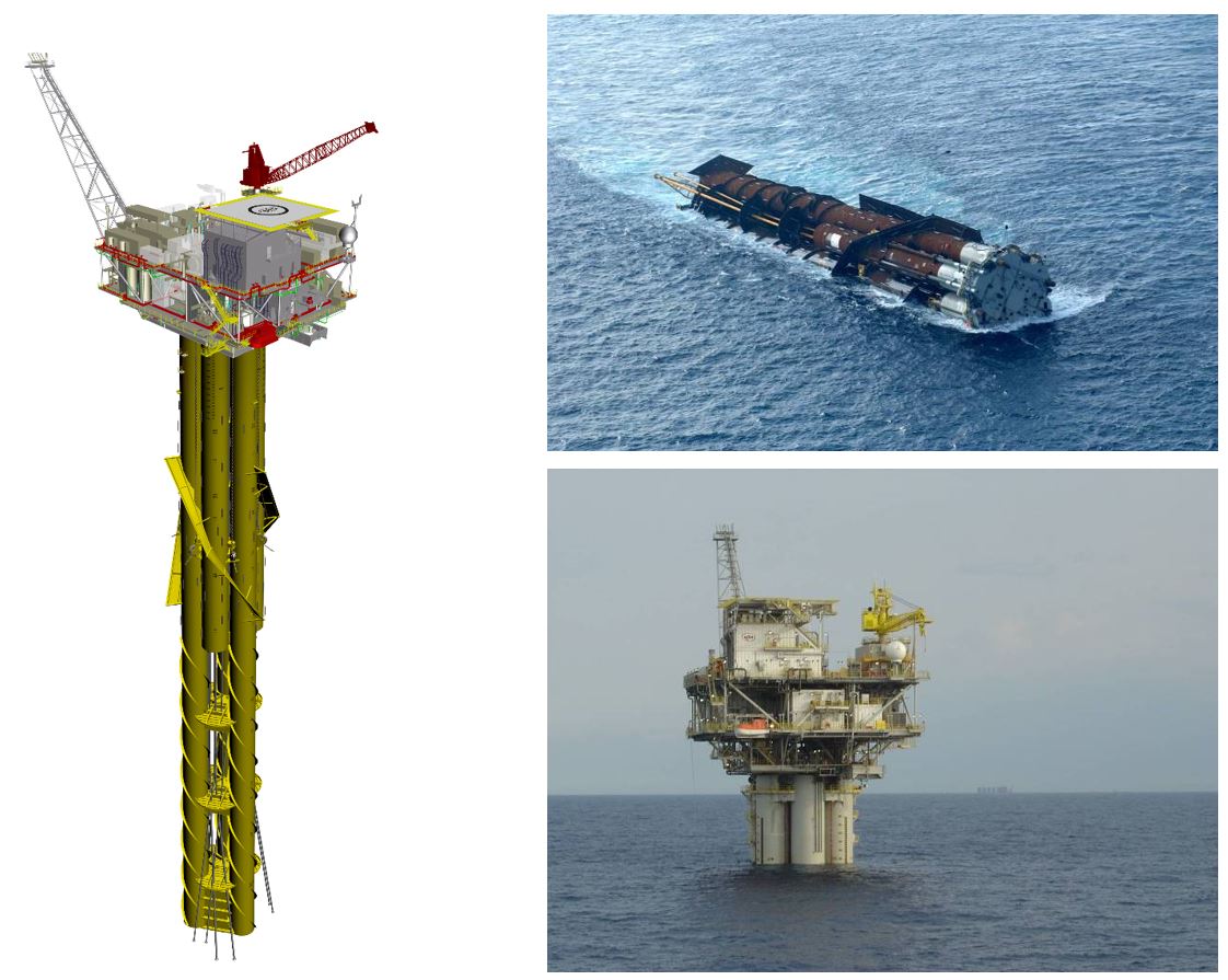
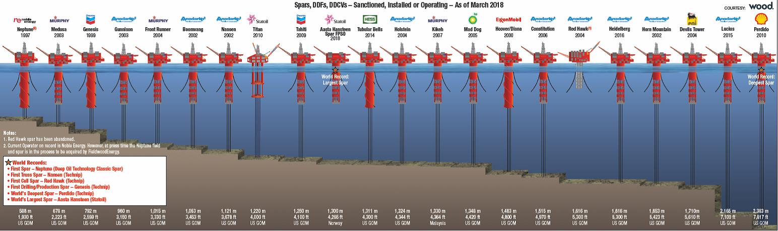
3.4 SPAR
Historically, SPARs were used as marker buoys, for gathering oceanographic data, and for oil storage (Shell Brent SPAR). The SPAR design is now being used for drilling, production, or both. The distinguishing feature of a SPAR is its deep-draft hull (about 90 percent of the structure is underwater), which produces very favourable motion characteristics compared to other floating concepts. Low motions and a protected centre wells-bay also provide an excellent configuration for deepwater operations. Water depth capability has been stated by industry (Technip) as ranging up to 3300m.
SPARs by virtue of the large draught have significantly reduced heave response and the possibility of oil storage. The reduced heave response permits the use of surface trees and rigid risers, thus allowing drilling and work-over without the need for an extra drilling rig. Indeed, this concept is not the only design (the other being the TLP) of floating production facilities where surface trees have so far been used.
Configured surface completed wells, a SPAR may be able to combine the best characteristics of the TLP and FPSO for fields where the reservoir can be reached from one drilling centre.
The following Figure 3.5, “Truss SPAR General Arrangement” presents the main components of a SPAR floater.
Three generations of SPAR design and technology have been developed during the last decade:
Each SPAR technology is briefly presented below:
3.4.1 Classic SPAR
The classic SPAR is a large, cylindrical hull moored in a vertical position. The innovative SPAR production system offers a stable platform that can accommodate dry trees, and support workover and drilling operations.
In 1996, the first SPAR technology is used on the Neptune field development, in the Gulf of Mexico, in 588m water depth.
3.4.2 Truss SPAR
This new design replaces the lower portion of the cylindrical hull with an open truss structure and bottom ‘soft’ tank, reducing size and cost, while improving heave motions.
The first Truss SPAR was installed in 2001 on Nansen & Boomwang Fields (Gulf of Mexico) at some 1120m water depth.
It should be noted that almost all subsequent SPARs are of the ‘Truss’ design.
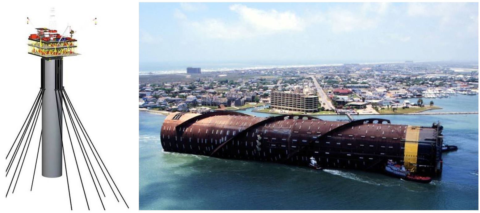
3.4.3 Cell SPAR
The Cell SPAR advantage (ease of fabrication and flexibility) makes it a more cost-efficient design, providing another option to reduce the reserve threshold for economic development of deepwater fields.
Red Hawk achieved first production in July 2004. The Red Hawk cell SPAR was fabricated at Gulf Marine Fabricators yard in Corpus Christi, Texas. The cell SPAR's hull is formed by seven hollow tubes, each 6m in diameter, used to provide both stability and buoyancy for accommodation, production equipment and related systems.
Refer to “Section A.1, “List of SPARs”” for further technical descriptions.
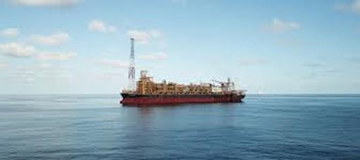
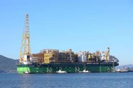
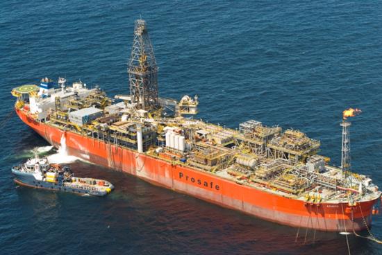
3.5 Floating Production Storage and Offloading Units (FPSOs)
For the combined production, storage and offloading to shuttle tankers, the ship-shaped floating structures are often the cost effective solution for subsea trees production facilities, Figure 3.10, “Turret Moored FPSO General Arrangement”.
The ship-shaped structure provides ample work area, deck load and storage capacity, structural strength, mobility and relatively cheap construction (in South East Asia) or tanker conversion. However, as a result of its large displaced volume close to the waterline, the wave induced response of these structures is quite significant. Therefore, the station keeping systems and dependent systems such as risers must be designed to accommodate these motions. The riser systems therefore need to be flexible. The advances in flexible riser technology have permitted ship-shaped vessels to be used as production platforms even in harsh environments, e.g. North Sea.
Both new-build FPSOs and tanker conversions have a role to play, with selection being based on the particular field requirements. More hostile environments and longer field lives favour the new-build but milder environment and shorter field lives are ideal for conversions, which can be executed more rapidly (see execution planning in Section ).

One of the complexities associated with ship-shaped structures is station-keeping. Excessive environmental forces result when waves are incident on the beam of such a structure. Thus a number of alternative methods of mooring these vessels such as CALM, SALM, articulated towers and soft yoke have been developed with the ultimate objective of permitting the ship to weathervane. More recently, internal turret moorings have been developed to allow weathervaning and provide higher levels of structural safety in harsh environmental conditions.
In extremely mild and or directional environments (e.g. West Africa) spread moored barges and ships have been used as floating production facilities as the weather from the beam is sufficiently small to allow the moorings to withstand these without having to weathervane.
In addition to FPSO’s, there have been a number of ship-shaped FSO (Floating Storage and Offloading systems) i.e. vessels with no production processing equipment used to support offshore field developments. An FSO is typically used as a storage unit for production processed from other platforms that are remote from infrastructure and lack an oil pipeline to transport the oil to the refinery.
Refer to Section A.2, “List of FPSOs” for further technical descriptions.
![[Tip]](tip.png) | Tip Click these links below for access to 3D resources: |
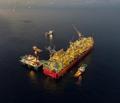
3.6 FLNG
Since the 1970s, oil and gas companies have been interested in the concept of FLNG projects with research conducted by firms such as Kvaerner and Moss Maritime.
Running in tandem with the development of FPSOs, FLNG projects have only recently begun to reach maturity with an increasing desire to developpe gas fields. Future FLNG projects could become the industry solution for the remote gas fields.
A non-exhaustive list of FLNG currently in production or under development is provided below:
PRELUDE FLNG (SHELL, Australia)
PFLNG SATU (PETRONAS, Malaysia)
HILLI EPISEYO (GOLAR LNG, Cameroun)
PFLNG1 (PETRONAS, Malaysia)
DELPHIN (DELPHIN LNG group, Gulf of Mexico)
FORTUNA (OPHIR ENERGY, Equatorial Guinea)
CORAL SOUTH (ENI, Mozambique)
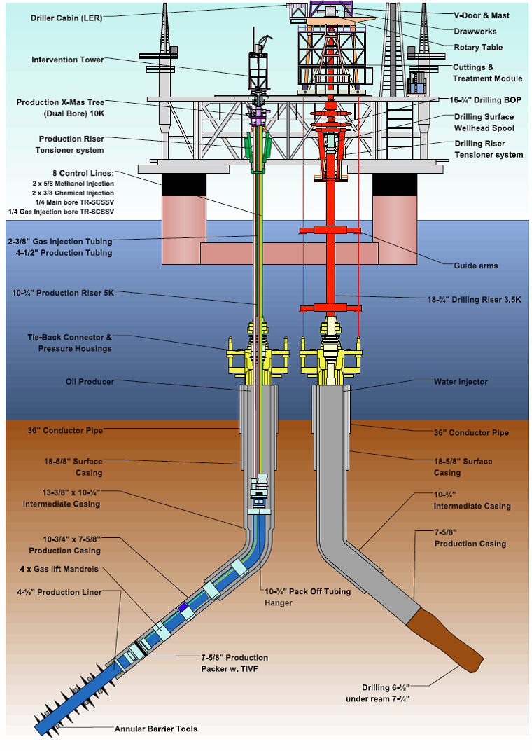
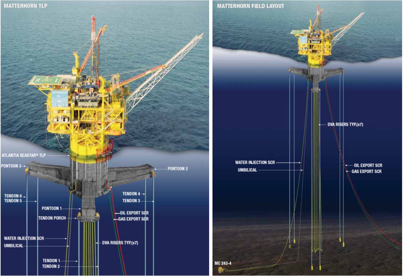
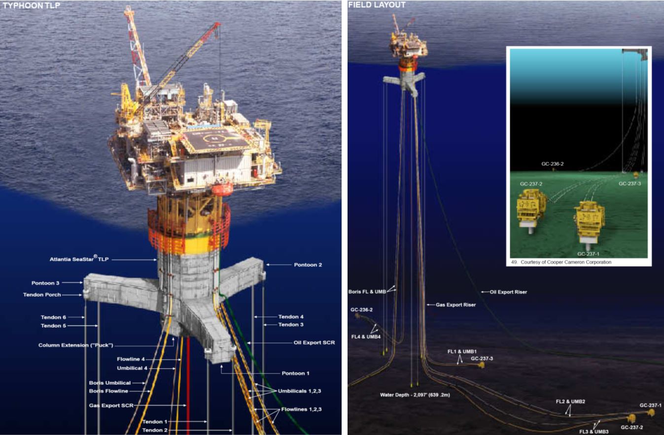
3.7 Tension Leg Platforms (TLPs)
Tension Leg Platforms (TLPs) typically have 3 to 6 vertical surface piercing columns supported by a complete ring of pontoons (see Figure 3.17, “Okume TLP – Trident Engergy (Equatorial Guinea)”). A TLP is maintained on location through the use of tendon moorings held in tension by the buoyancy of the hull. The mooring system is a set of tension legs or tendons attached to the platform and connected to a template or foundations on the seafloor.
Tendons are typically steel tubes with typical dimensions of 0.5m to 1m in diameter with up to 3 inches of wall thickness. A typical TLP would be installed with as many as 16 tendons.
Most foundations are templates laid on the seafloor, then secured by its own weight and steel piles driven into the seafloor by use of a hydraulic hammer, but other designs can be used such as a gravity (concrete) foundation. The foundations are built onshore and towed to the site.
As many as 16 steel piles with typical dimensions of 96” in diameter and up to 418 ft (127m) long are used (one for each tendon).
The vertical tethers are designed to avoid resonances by putting the natural periods in heave, pitch and roll below the wave periods and those in surge, sway and yaw well above the wave period range. The high strength tethers of a TLP limit the important motions and allow uninterrupted drilling and the use of surface trees.
TLPs are sensitive to payload through its effect on tether tensions. Excessive deck load may result in slack tether conditions in large waves (Compression in tethers shall be avoided). They are therefore not used for oil storage.
TLPs are in principle capable of being reinstalled at a different location when production at the initial field comes to an end.
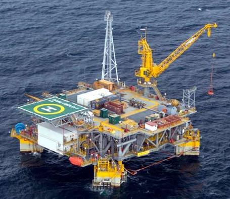
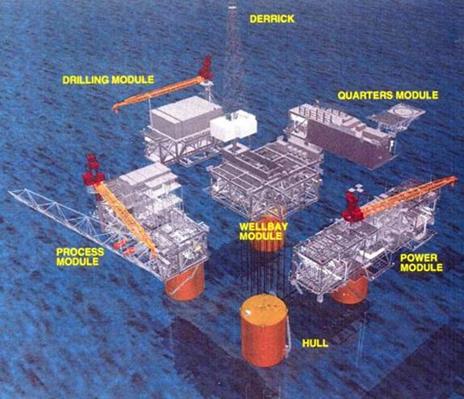
Early in TLP development, industry discovered that it is cost effective to build the surface facility in separate units (modules), assemble them at shallow inshore location, and then tow the completed TLP to the site. The modules that are part of a typical TLP include the wellbay, power, process, quarters, and drilling; they are secured to the deck, which is attached to the hull. The following schematic presents the topside of the Mars TLP.
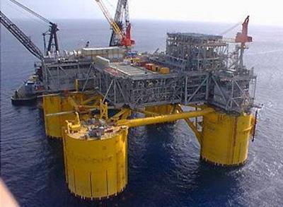
The following Figure presents the installation of the Ursa TLP Modules (SHELL – GoM).
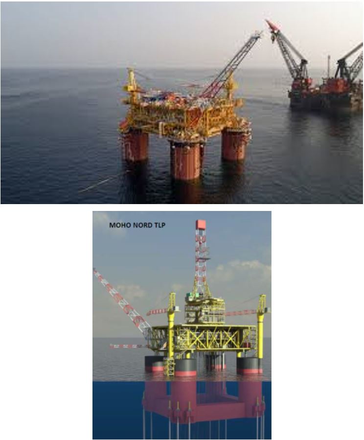
One of the main advantage of Moho Nord TLP is the possibility of Drilling, Well intervention and completion and Production SIMOPS.
There is also interest in mini-TLPs, supporting just the well system with minimum facilities. Several designs have been made in recent years offering an alternative to subsea templates with the intervention advantages of surface completed wells.
Refer to Section A.3, “List of TLPs” for further technical descriptions.
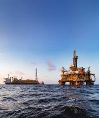
3.8 Semi Submersibles
Semi-submersibles are a common type of floating structure used in the exploration and production of offshore hydrocarbons. These structures often comprise two submerged horizontal pontoons which provide the main buoyancy for the platform but act as catamaran hulls when moving location at low draft. Alternatively a ring pontoon may be used for a fixed location. Typically, four to eight vertical, surface piercing columns are connected to these pontoons. The columns themselves may have cross and horizontal bracings to provide structural strength and triangulated rigidity for the platform.
The deck of the platform is located at the top of the columns. The minimal water plane area contributed by the vertical columns results in long heave, pitch and roll natural periods as far as possible above wave periods (with heave natural period being a critical parameter for drilling units) and the heave, pitch and roll hydrodynamic loading can be minimised at the dominant wave period by careful selection of pontoon volume and water-plane area. These features lead to good response characteristics in typical operating weather conditions.
The good response characteristics provide an excellent platform for both drilling and production uses. However the improved motion compared with ship-shaped vessels is achieved at the expense of increased structural complexity and sensitivity of stability and draught to payload and position. Owing to this sensitivity, and because they have mainly been designed as drilling units, they do not normally have any oil storage capacity.
Station keeping is achieved primarily by chain/wire mooring systems. A number of rigs are also fitted with azimuthing thrusters capacity to relieve loads in the mooring system and assist in transit. A number of semi-submersible drill rigs also have dynamic positioning systems which permit their operation in deeper waters where moorings may be impractical.
Most semi-submersible floating production systems are based on converted drilling rigs. For larger fields in deeper water the topside payloads become larger so that only the larger drilling rigs are suitable for conversion to FPS unless very substantial conversions (providing extra buoyancy and stability) are undertaken. However, the increasing demand for drilling deep water wells is forcing up day rates of the limited number of large deep water rigs. In this situation it is counter productive for oil companies to convert large drilling rigs and building new semi-submersible floating production systems is preferred.
Refer to Section A.4, “List of Deepwater Semi-Submersibles” for further technical descriptions.
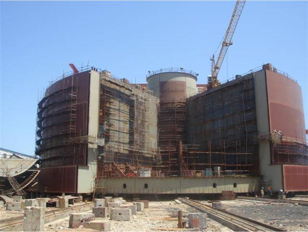
3.9 Sevan Stabilised Platform (SSP)
Sevan Stabilised Platform (SSP) is a new, cylinder shaped platform type for floating production, storage and offloading of oil and gas. The SSP is basically a mono-hull with circular shape. Unlike the SPAR design, the SSP hull is wider than it is tall, because the operational draft is typically less than a third of the diameter. The characteristic dimension for the SSP is the diameter.
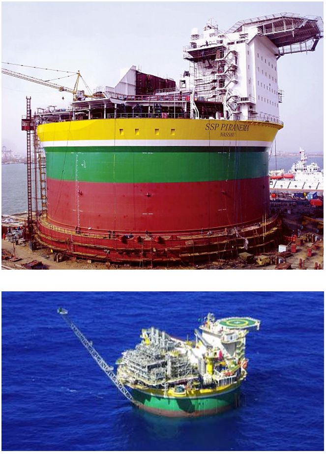
The circular shape dispenses the unit of any heading changes, because the seas face the same vessel hydrodynamic resistance, whichever direction they are coming. Consequently, the SSP does not need turrets or swivels.
The SSP stability principles are the same as for a ship-shaped vessel. The large water plane area provides high stability, resulting in a large deck load capacity. The available deck area is large and can be increased with a cantilevered deck. This allows all activities to be conducted above deck, with cargo, ballast, and liquid supplies placed inside the hull for improved operational safety.
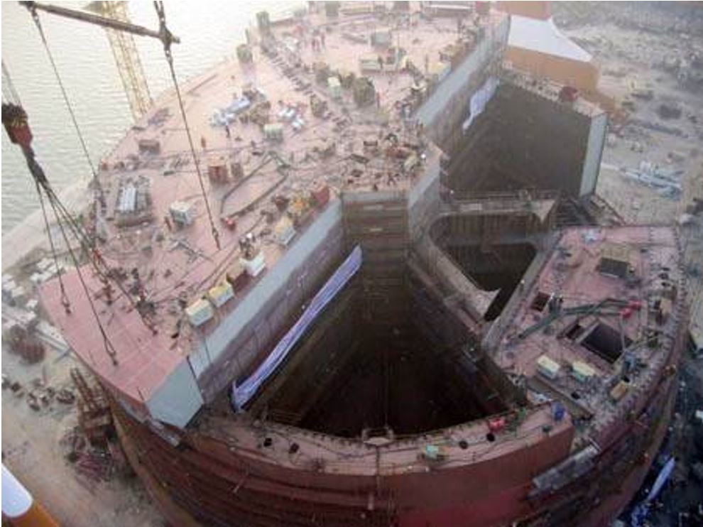
The ballast tanks are at the SSP periphery, giving her a double-hull configuration. The SSP symmetrical shape allows access to all tanks, ballast, and cargo from a central compartment (see Figure 3.28, “SSP Piranema Tanks - PETROBRAS”). No piping is needed inside any of the tanks, which simplifies the engineering design, construction, and operation. It is estimated that only around 30% of piping normally used in a conventional FPSO will be needed in the SSP. The cargo tanks are protected by the ballast tanks to prevent leaks to the sea in the event of a collision.
At the base of the SSP lies a bilge box (see Figure 3.29, “SSP Piranema Bilge Box – PETROBRAS”) that provides damping to the vertical and angular motions of the vessel. The bilge box is responsible for enlarging the vessel added mass and increasing the damping.
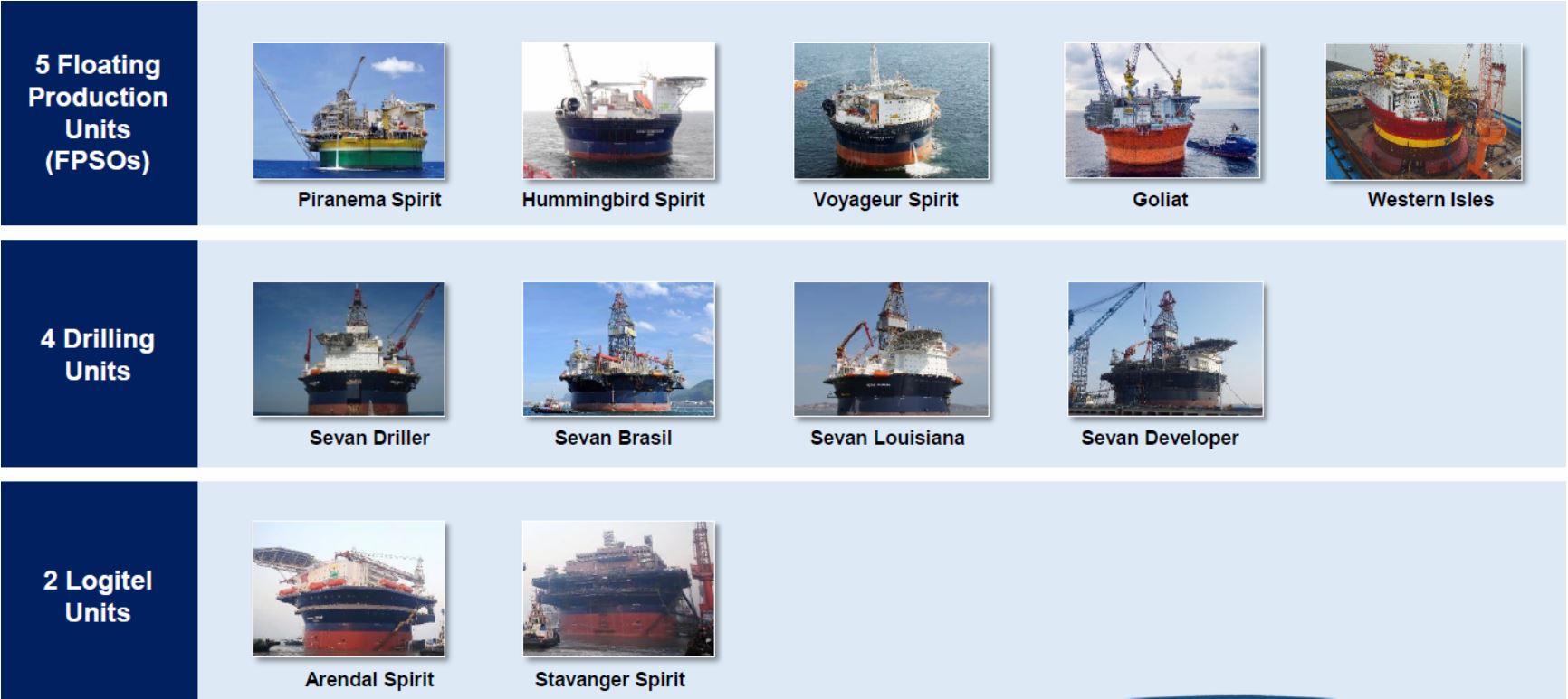
At the end of 2016, The Sevan Company had 11 Sevan platforms leased to clients:
five Floating Production Storage and Offloading units
four drilling units
two logitel units
In 2017, Sevan Marine has signed a long-term framework agreement with ExxonMobil in the field of floating liquefaction facilities (FLNG).
Refer to Section A.5, “List of SSPs” for further technical descriptions.
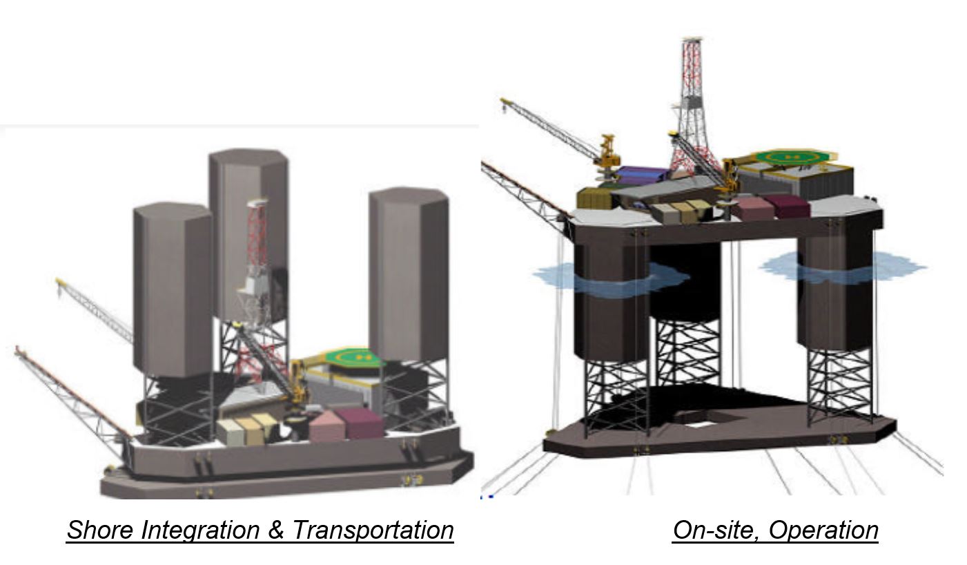
3.10 Deep Draft Semi-Submersibles
The wave heave response of ultra-deepwater floater is a key factor for the design of drilling or production risers and mooring systems. In view to reduce further these mooring lines and riser loads, the industry is currently developing and promoting the deep draft floaters, mainly:


A well advanced development of Technip EDP (Figure 3.33, “TECHNIP Extended Draft Platform (EDP)”) has the following key features:
Wellhead (dry trees) and drilling support.
Floating production support.
Full integration onshore
Shallow water quayside skidding and integration of process modules.
Tow-out and self-elevating/installation to pre-installed mooring lines.
Suitable for Topside from 2 000t and up to 50 000t+.
Wave motion characteristics (obviously better than a semi-submersible) and matching the SPAR wave responses. => All existing riser technology field proven developed for SPAR is fully usable for EDP
Composed of:
Barge type deck
Topsides facilities on top of deck
Legs (buoyant column + truss)
Pontoon (heave plate)
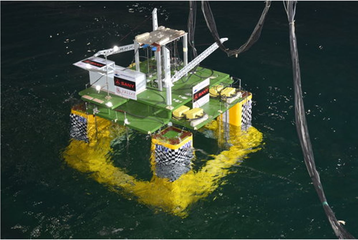
The below TCDD-Semi is a new design concept jointly developed by OTL and SANY for dry-tree service. It features, among other items, longer hull geometry with a gradually varying column cross section and skirt plates fitted on the pontoons. These creative aspects contribute to significantly better heave motion responses in waves, pre-service stability, vortex-induced motions (VIM), etc. .