6 Mooring Systems
![[Tip]](tip.png) | Tip Click these links below for access to 3D resources: |
6.1 Mooring System Requirements for Floating Structures
The two major requirements for a mooring system are:
To withstand the environmental (extreme and fatigue) loads while limiting FPU offset and keeping it on station.
To be sufficiently cost effective so that the overall economics of the mooring system remain viable.
The following list shows more specifically the main functional requirements that need to be considered for permanent moorings systems:
The primary purpose of the mooring system is to maintain the floating structure on station within specified tolerances under normal operating load and extreme storm load conditions, with or without damaged mooring line(s).
The excursion of the Floater must not permit excessive tension loads in risers and umbilical and should allow for suitable specified clearance distances between devices in multiple installations.
The mooring system must be sufficiently compliant to the environmental loading to reduce the forces acting on anchors, mooring lines and the floater itself to a minimum; unless the stiffness of the mooring itself is an active element (taut moored) in the wave energy conversion principle used.
All components must have adequate strength, fatigue life and durability for the operational lifetime, and marine growth and corrosion need to be considered.
A degree of redundancy is highly desirable for individual devices, and essential for schemes which link several devices together.
The system as a whole should be capable of lasting for the operating life of the platform (typically 20-30 years or more) with no replacement of any particular mooring components.
The mooring must be sufficient to accommodate the tidal range at the installation location.
The mooring system should allow the removal of single devices without affecting the mooring of adjacent devices.
Removal of mooring lines for inspection and maintenance must be possible.
The mooring must be sufficiently stiff to allow berthing for inspection and maintenance purposes.
Contact between mooring lines must be avoided.
Contact of steel wire and polyester line components with sea bed must be avoided during the operating life of the platform
The mooring system should be designed as an integral element of the overall system to keep the FPU at optimum orientation relative to the waves, wind and current conditions. An active mooring system (e.g. DP, Section Section 6.5, “Dynamic Positioning Station Keeping System”) may increase initial (‘capex’) costs, but an enhanced performance would mean higher production up-time and may justify these higher costs.
There are a range of rules, guidelines and regulations for mooring systems published by various authorities (e.g. BV, DNV, API, ABS) around the world. The most stringent of these apply to the design, analysis and maintenance regulations for the floating structures of the offshore oil and gas industry. The reasons for this stringency is the risk of substantial loss of life and the danger of environmental pollution should failure occur.
6.2 Mooring Configuration for Floating Structures
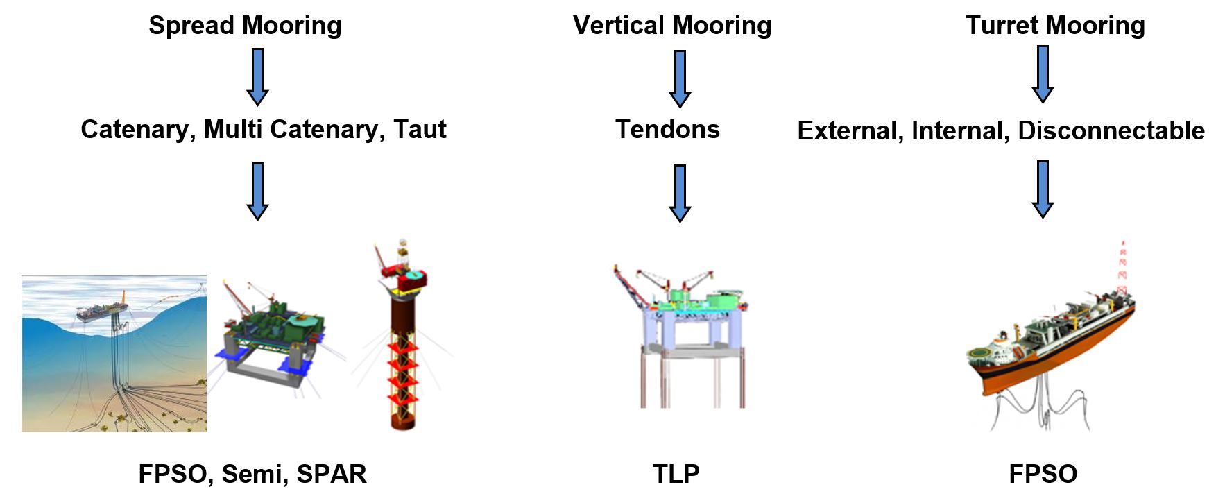
A variety of mooring configurations have been developed over time for the station keeping of floating vessels. Increasingly specific requirements for the station keeping of floating vessels have resulted in the evolution of sophisticated mooring designs. Spread moorings using catenary lines are common for semi-submersible platforms and vertical tethered moorings for TLP.
In some cases spread moorings are not suitable since they essentially fix the heading angle. To enable a vessel to weathervane into the incident waves a rotating turret mooring or a single point attachment from the vessel to a fixed or floating structure/buoy is utilised, hence the term Single Point Mooring (SPM). Furthermore active mooring or dynamic positioning (thrusters) could be a station keeping option.
The following schematic presents the different mooring configurations available for deepwater applications:
6.2.1 Spread Moorings
The spread mooring system consists of an anchor arrangement deployed to connect the ship directly to the seabed. The mooring lines are emanating from the four corner of hull (e.g. FPSO, Semi-Submersible) and are anchoring into the seabed. This anchoring system moors the floater at a fixed location and at a fixed heading. The heading of the system is determined, based on the prevailing environmental conditions (wave, wind & current) at the specified offshore location. These systems are recommended for semi-submersibles and floating structures less sensitive to environmental loads and for ships on locations with mild environmental conditions having the same prevailing wind and wave direction all year through, e.g. West of Africa.
The main differentiator between the spread moored system and buoy/turret moorings is that the product (oil) transfer functions are not integrated in the former. They are completely separated.
The following Figure 6.2, “FPU typical Spread Mooring System” presents the typical general arrangement onboard a spread moored FPU.
There are three main ways to secure the mooring lines on the hull of a FPSO/FPU moored in spread:
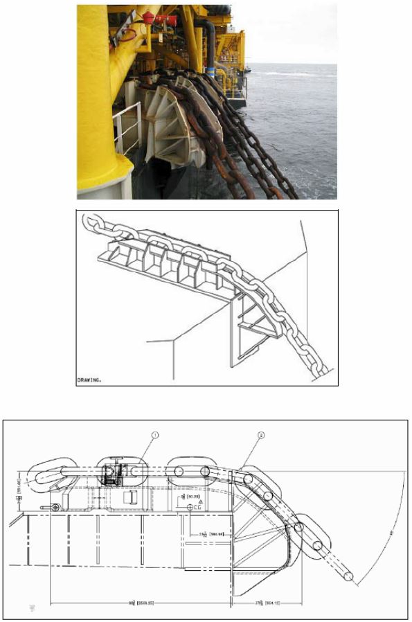
Dry termination system: (NKP barge, Alima and MHN FPU, Azurite FDPSO,…)
In that case, the mooring system on floating unit side is made of a stopper and an overboarding chute (bending shoe). All these pieces of equipment are located at deck level. They are made of simple and strong steel shapes (no articulated piece in the system). The arrangement of the bending shoes implies to tension the line in its direction. The line tension is taken up at deck level. The chain is locked in the stopper and many links lay then on the bending chute.
The monitoring of this equipment is done from the deck.
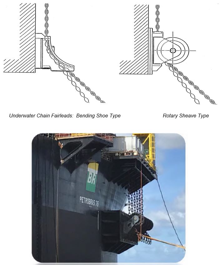
Underwater Chain Stopper and Fairlead (UCSF): (AKPO, USAN, CLOV, DALIA, PAZFLOR and EGINA FPSO,…)
The stopper is directly combined with the fairlead. It is then composed of a horizontally swivelling fairlead and a vertically pivoting chain stopper mounted outboard of the fairlead. The device can rotate freely in both vertical and horizontal directions in response to environment changes so that the relative motion between the vessel and mooring line occurs at the fairlead stopper.
Tension is removed from the vertical part of the line and around the underwater swivelling fairlead. The line tension is then taken up in the strong bottom part of the hull. The whole monitoring can only be done underwater. All loads due to variations in chain direction relative to the vessel are taken up in bushings limiting chain fatigue under OPB/IPB phenomena.
Deck-mounted mooring equipment general arrangement shall consider foot print, interface with laydown area, living quarters, supply vessel…
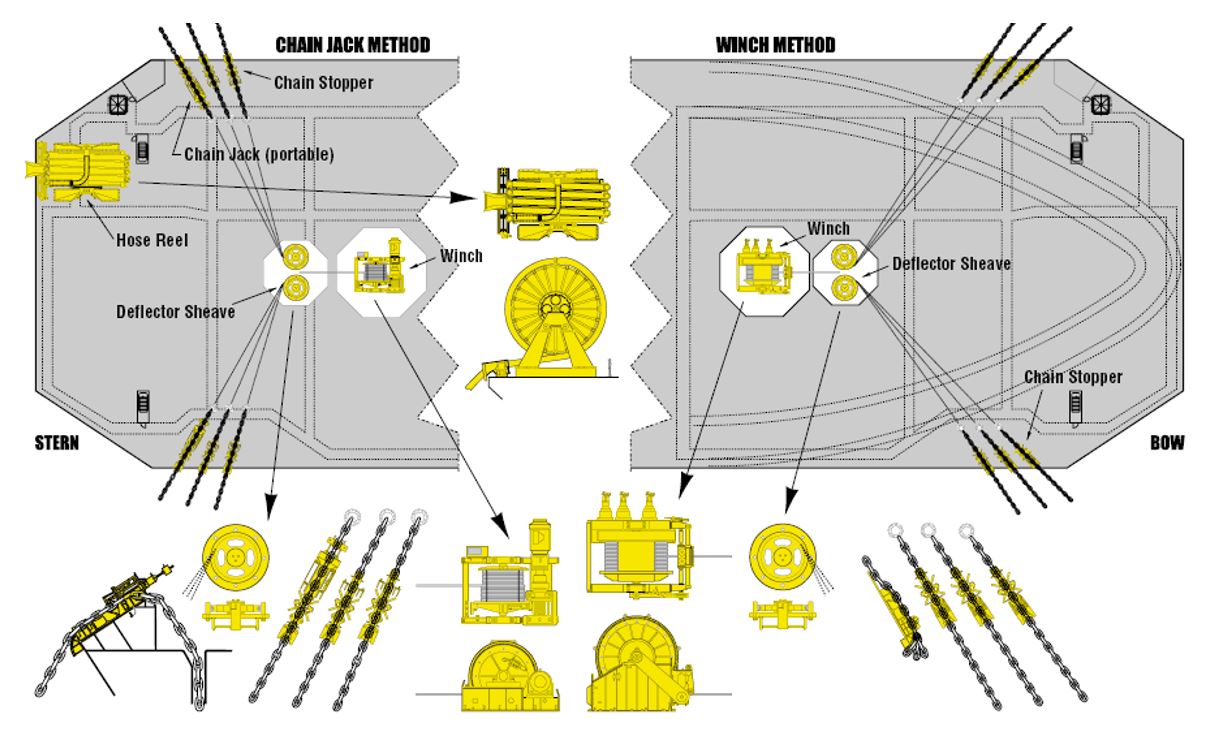
The most suitable deck arrangements for each fairlead system, associated to a given tensioning system are described hereafter:
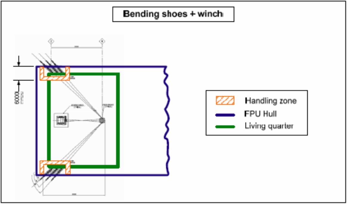
Bending shoes and winch
For each end of the hull, the following equipment is mounted at deck level: bending shoes and stoppers (one per line), one deck sheave, and one large mooring winch. Lines paths are also to be taken into account to get the total footprint of the system.
The foot print of the whole system may be higher than 20m large and some space has to remain free on deck for winch wire paths. Attention shall be paid to remove bending shoe from laydown area.
Bending shoes, pull in winch and horizontal chain stopper
The only difference from previous configuration is the use of swivelling horizontal chain jacks for tensioning. The winch is only used for pull-in, and so a smaller one would be necessary. Note that this system requires more space at the centerline, which can be ever more complicated for the fore clusters.
As chain lockers can not be used with this system, specific area and means have to be defined to handle the chain over length overboarding.
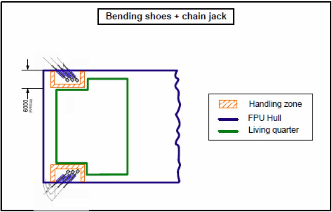
Bending shoes with integrated chain jacks
This alternative provides a compact system at deck level. The tensioning system is directly mounted on the bending shoe. The chain is then stored in a chain locker; there is no need for specific area to handle the chain over length overboarding.
The footprint at deck level is limited to the bending shoe and the chain locker at sides, no space is needed at the centerline.
Using integrated chain jack on bending shoes allows mitigating the projection of dedicated mooring area in the living quarter. At least, the bending shoes could be mounted in cantilever to reduce even more the projection.
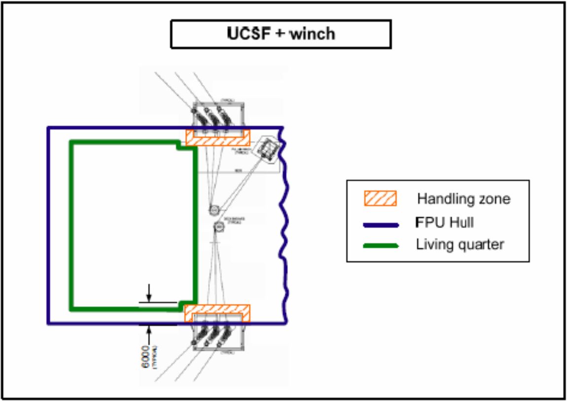
UCSF, winch and chain jack
For each end of the hull, the following equipment is mounted at deck level: one deck sheave, one pulling winch, one vertical chain jack per line. A chain locker is to be considered. The footprint of the whole system is typically around 20 m large and some space has to remain free on deck for winch wire paths. But, using UCSF, the winch lines are restrained to be in line with the mooring lines. So the lines path can be optimized to reduce the footprint of the whole system.
With this equipment, as the fairleads and stoppers are located underwater and protected by the mooring protectors, the risk of drop objects damage is mitigated. The supply approach no longer risks damaging the lines for the same reasons.
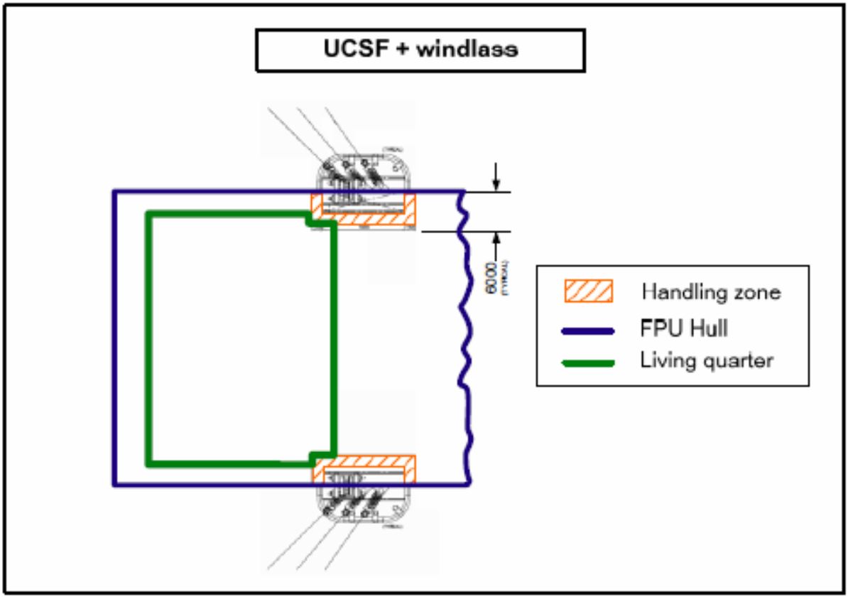
UCSF and windlasses
For each end of the hull, the following equipment is mounted at deck level: one windlass per cluster on a trolley, one chain locker. No dedicated area is to be taken into account for any other equipment. The footprint of the whole system is approximately 15 m large, no space is needed at the centerline.
As chain lockers are associated with windlasses, there is no need for specific area to handle the chain over length overboarding.
The different hull and deck-mounted mooring equipment arrangement are compared vis-à-vis the following criteria:
Fatigue life:
For UCSF systems, the chain stopper mounted on the latch housing assembly is free to follow the increasing catenary angle taken by the chain. Thus, the interlink angle between the link locked in the stopper and the first free link is typically 0.2° at best. OPB/IPB phenomena are thus decreased.
With dry fairlead system, many chain links lay on the overboarding chute. It means that several links can be concerned by cyclic loadings and then fatigue issue. Moreover, due to the friction of the links on the plate, the interlink angle is typically about 3-4°, which is way more detrimental for the fatigue life of the link.
Corrosion:
When using UCSF, the whole mooring system subjected to stress is underwater and so it is less prone to corrosion. Likewise, as all the mooring chain beyond the stopper is also underwater, corrosion effects are less important thanks to cathodic protection.
With dry fairlead system, equipment and mooring lines are exposed to environment (sea, air, spray…) and are so quite sensitive to corrosion. Anyway, it is possible to limit the influence of corrosion on design (chain diameter), by using additional coating or using a replacement policy for the exposed top chain length. It is indeed possible to replace a part of the top chain after 15 years for instance. The chain diameter would then be designed for a shorter life span (fatigue and corrosion wise). Particular attention would also be paid to equipment corrosion where only paint can limit the exposure to environment.
Safety:
One of the main interests of using UCSF is to prevent mooring systems to be exposed to fire on board. Moreover, they provide a clear access to the FPU, reducing risks of collision between boats and mooring lines. As stoppers are located at a lower part of the hull and below the free surface, only the tensioning equipment may be threatened by dropped objects.
It may be risky to have the whole fastening system at deck level, below crane outreach. Drop objects analysis may lead to design adapted reinforcements and protection to ensure the integrity of mooring lines and equipment. Moreover, special care shall be paid to ensure free access to supply boats at portside.
For these reasons, bending shoes shall not be located close to the laydown area.
Inspection & maintenance
As they are located at deck, dry fairlead systems allow a very easy inspection and maintenance if required. Monitoring on deck is thus reliable.
UCSF require divers or remote-controlled devices to be inspected and their maintenance is way more complicated. Underwater monitoring has been found not reliable on site (See Dalia, where the monitoring system was unable to detect a line breaking). But they are normally designed as a permanently installed unit, which does not require maintenance or replacement.
Operations
Today, installing lines procedures in case of UCSF are diver less. It means that the whole system has to be remotely controlled from the FPSO/FPU. Such systems could be considered as less robust and may be damaged during towing phase (see USAN project). Sea fastening for wet towing has then to be optimized.
Dry fairleads ease heavily the hook-up operations, as all equipment are visible from the deck and can be more easily handle.
An alternative to the above typical mooring tensioning systems is the use of uni-joints and in-line mooring connector (ILMC) tensioning system, located some distance below the surface that is pre-tensioned after connection to:
This type of mooring system implies that:
There no need any deck-mounted tensioning equipment (HPU, winch, Chain jack,…), which simplifies the mooring system and reduces its cost
Re-tensioning the line during the field life is not possible, except with an external means
Specific requirements associated with the station keeping of floating structures have resulted in the application of different materials for mooring lines as well as different configurations i.e. Catenary, Multi-Catenary, Taut, as follows:
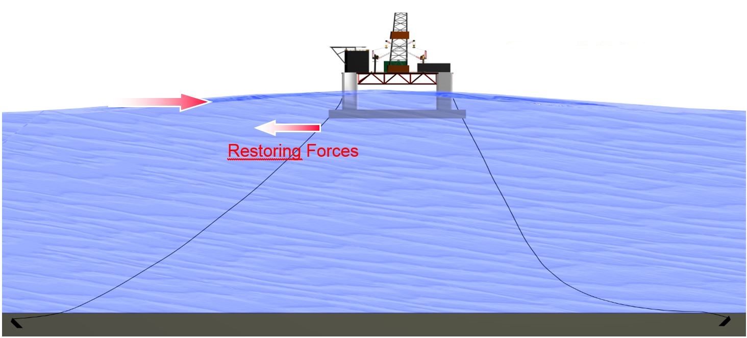
6.2.1.1 Catenary Mooring
The mooring lines of a free hanging Catenary configuration arrive horizontal to the seabed so that the anchor point is only subject to horizontal forces. The restoring forces are mainly generated by the weight of the mooring lines returning the system to equilibrium, see Figure 6.14, “Catenary Moorings”.
6.2.1.2 Multi-Catenary Mooring
The catenary mooring lines incorporate weights and buoys to form S or Wave type configurations. Steep and lazy touches down points are possible.
6.2.1.3 Taut Tether Spread Mooring
The mooring lines of a Taut Spread arrangement arrive, typically at an angle to the seabed with the anchor point capable of resisting horizontal and vertical forces.
The restoring forces are mainly generated by the elasticity of the mooring line components.
6.2.1.4 Semi-Taut Spread Mooring
The mooring is a combination catenary and taut effects:
Catenary effect at low tensions
Taut effect at high tensions
6.2.2 Vertical Mooring (Tendon)
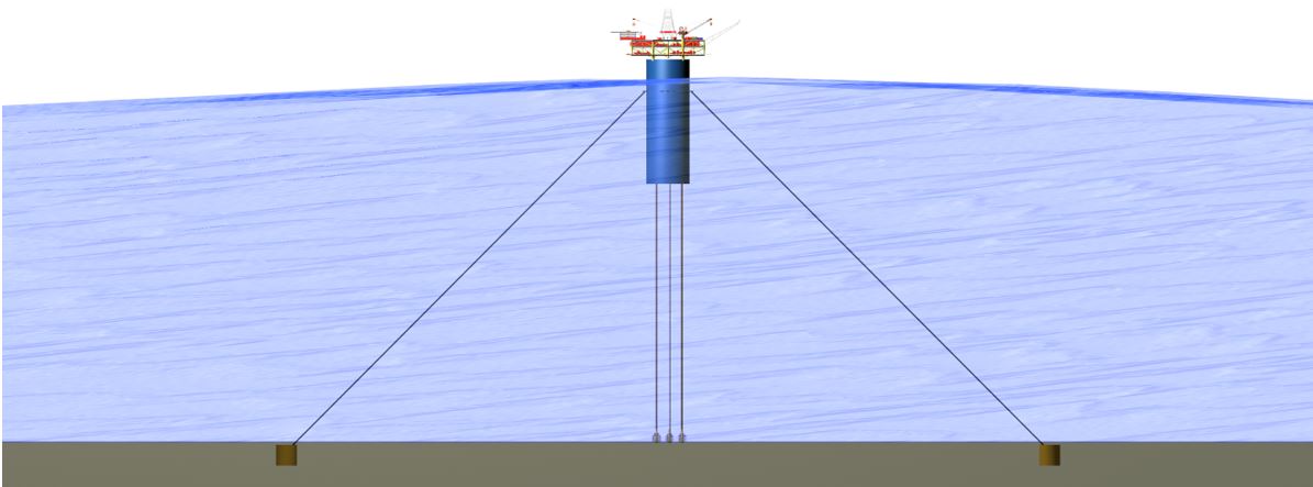
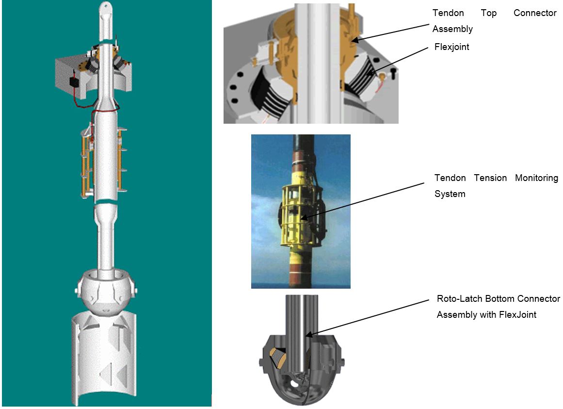
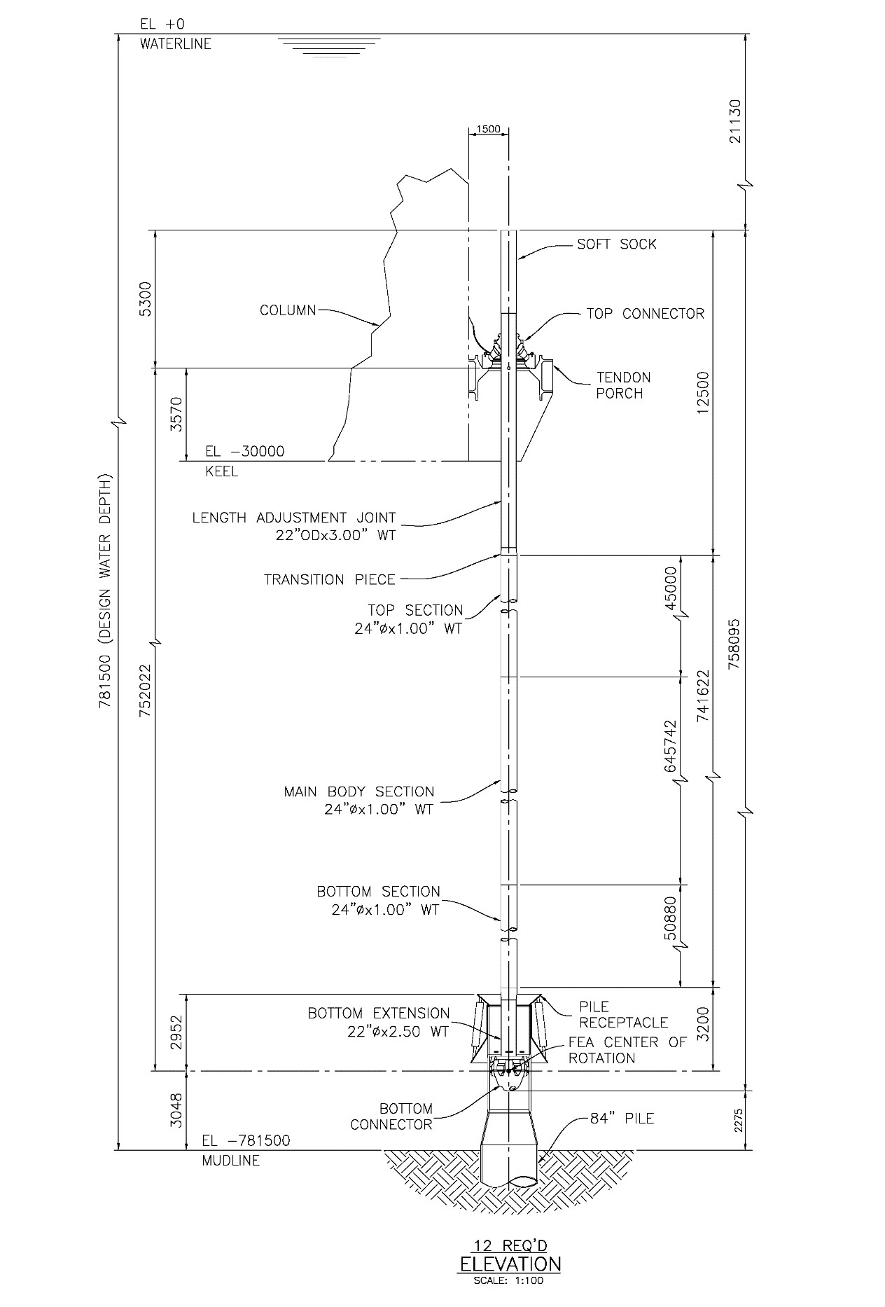
The mooring system of a TLP is vertically oriented and consists of tubular steel members called tendons. These tendons are highly tensioned using excess buoyancy of the platform hull. The following Figure 6.17, “Tendon System Description” presents the tendon system.
For degrees of freedom in the vertical plane (heave, roll and pitch), the motions are effectively eliminated by the axial stiffness of the tendon system. As such, the sensitivity of critical operational aspects including drilling and the support of Top Tensioned Risers (TTRs) to vertical motion is eliminated. The motions in the horizontal plane (surge, sway and yaw) are controlled by tendon tension.
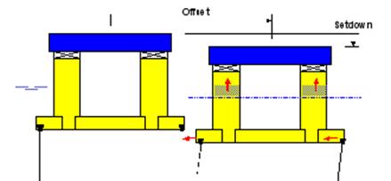
The highly tensioned tendon system limits horizontal offsets to a very small percent of water depth. The high tendon stiffness also reduces the system's vertical natural periods to a level well below that of the dominant wave energy (Section ). As a result, dynamic amplification of vertical motion is nearly non-existent and the platform has limited heave, roll and pitch motions. Essentially, the vertical motions correspond to the stretch in the tubular steel tendons. For even the largest Gulf of Mexico hurricane waves of 25 m, the corresponding vertical motions of the platform are limited to a few centimetres.
Offset with set-down is another key aspect of TLP behaviour; this is illustrated in Figure 6.19, “Definition of TLP Offset and Set-down”. The TLP experiences offset when acted upon by a horizontal force. These forces arise from wind, waves, current and other sources such as SCR weights. Offset will be accompanied by an associated increase in TLP draft. This is called set-down. If a TLP is offset to a given position and released, the horizontal tendon tension component due to offset and the increased vertical tendon tension component due to set-down act together to restore the platform to its vertical position.
6.2.3 Turret Mooring
Turret structures are designed to anchor the vessel, while allowing “weathervaning” of the floaters to accommodate environmental conditions, permit the constant flow of oil and production fluids from vessel to undersea field, all while being a structure capable of ‘quick disconnect’ in the event of emergency.
6.2.3.1 External Turret
The External Turret Mooring system comprises a steel box type structure that can be close or extended some distance from the bow or stern of FPSO, providing a foundation for a rotating bearing arrangement and a turret. This is the preferred option for converted FPSO.
The bearing accommodates a fixed chain-table to which mooring chains and fluid transfer hoses are attached. The chain legs are anchored to the seabed either by anchors or piles. Product and utility connections are made between the facilities on the FPSO and the seabed via a swivel stack in the turret, allowing the tanker to weather vane around the fixed part whilst continuing production.
6.2.3.2 Internal Turret
The Internal Turret Mooring system is integrated into the forward end of the FPSO and is supported on a large roller bearing, located either inside a moonpool towards the bottom of the vessel, or at deck level.
The outer rotating race of the bearing is connected to the vessel, while the inner race is attached to the fixed part of the turret.
Above deck level, a manifold structure enables connection between the lower turret and the swivel stack.
6.2.3.3 Disconnectable Turret
The disconnectable turret mooring system allows the exploitation of reserves in locations where severe weather conditions such as typhoons, hurricanes or ice packs, might threaten the safe operation of the facility. Two basic concepts were developed:
The Riser Turret Mooring (RTM)
The RTM arrangement comprises a tanker or barge bow mounted riser turret, incorporating a rapid and independent disconnectable risers and mooring system. The disconnection is achieved automatically in two stages; first the risers are isolated, then the riser column disengaged utilising large hydraulically operated collet-type connectors. After disconnection, the column remains on location and the tanker sails away.
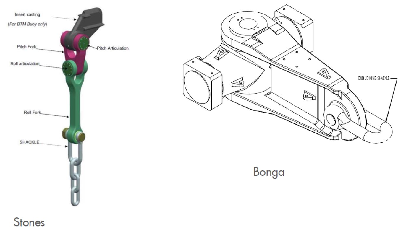
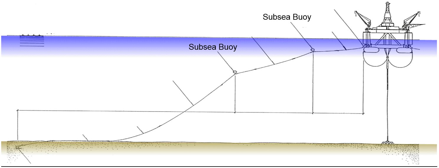
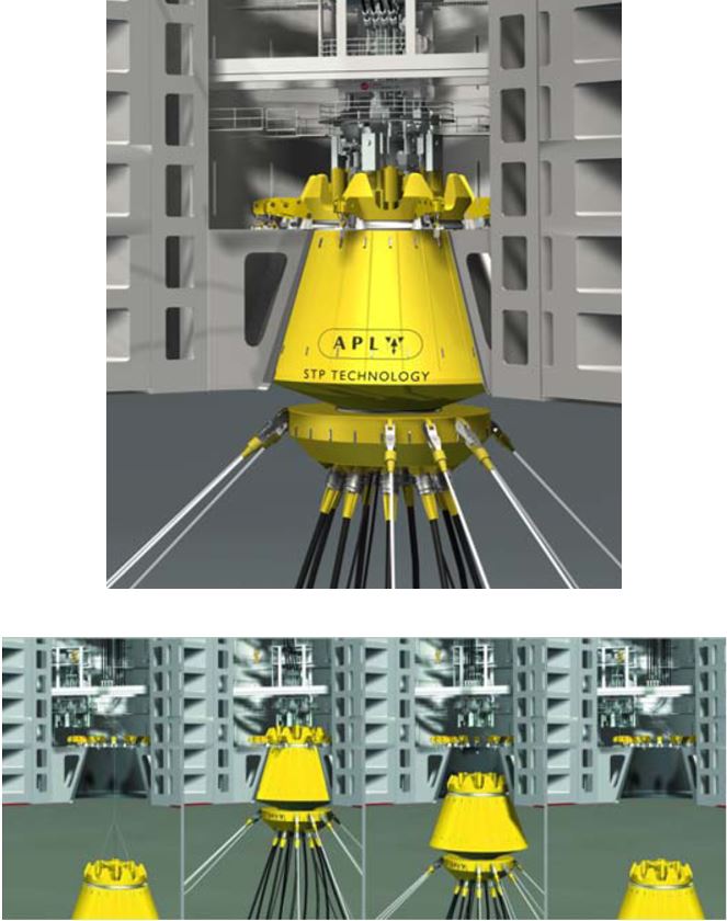
The Buoy Turret Mooring (BTM)
The BTM system comprises an internal turret integrated into the forward end of the floaters (e.g. FPSO, FSO). The mooring buoy is connected to the turret structure by a large collet-type connector. The buoy is designed to have enough buoyancy to support the weight of the chain legs and risers. To reconnect, the mooring buoy is simply pulled up under the tanker using a wire rope hauled in on a drum winch.
Other similar subsea buoy turret concepts are proposed by APL contractors, see Figure 6.25, “Submerged Turret Production system (STP) Connect & Disconnect Sequences”.
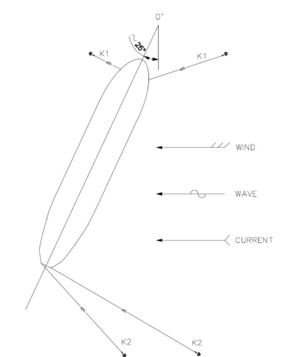
6.3 The DICAS Mooring System Concept
Developed by PETROBRAS to be an alternative for permanent mooring systems on FPSOs and FSOs intended to operate offshore Brazil, the DICAS (Differentiated Complacent Anchoring System) concept is in fact a sophistication of the well known “spread” mooring system.
What differs a DICAS mooring system from a conventional spread mooring system is that different stiffness are applied on the mooring lines located at the bow and at the stern of the vessel, allowing the system to be partially weathervane.
A DICAS mooring system is characterised by its ‘acceptable mean yaw angle’:
Small Yaw System (SYS) where the mean yaw angle is limited up to 30°.
Large Yaw System (extreme conditions) with mean yaw angle up to 80°.
The differences in stiffness between the bow and stern anchor lines are obtained with different patterns and pre-tensions for each set of mooring lines. The mooring system allows the vessel to have considerable large yaw angles according to the direction of the environmental resultant forces.
Following Figures show the semi-weathervane concept of the mooring system on its initial equilibrium position without the action of the environmental forces and under the action of a beam sea environmental condition with wind, waves and current. The different stiffness at the bow and stern allows the unit to have a mean yaw angle of about 25° to 30°, reducing the incidence angle of attack of the environmental loads.
The heading of the platform moored with a DICAS system shall be defined in accordance with the dominant environmental direction at the installation site. Normally the bow is orientated towards the worse environmental direction to reduce the platform roll motion in extreme environmental conditions. On the Brazilian coast, the more severe storms come from the South and Southwest directions, and the most frequent environmental direction comes from the Northeast. In this basis the best heading for the FPSO/FSO will be S-SW direction (202.5° from North).
The dynamics of a DICAS mooring system has a very non-linear behaviour, henceforth special care shall be taken when designing and performing the mooring system analysis.
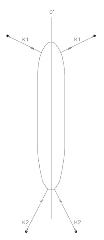
Figure 6.27 - Equilibrium Position of the Vessel under the Action of Beam Seas Mean Environmental Forces
6.4 Mooring System Components
| Tip Click these links below for access to 3D resources: |
6.4.1 General
Primary mooring components are the mooring line and anchor. These components must be chosen with consideration of the mooring configuration, location and the requirements of a long term mooring.
Requirements for components of a long term mooring are discussed in the offshore standard DNV-OS-E301 “Position Mooring” (October 2004) (Ref. ), where long term mooring is defined for floating units positioned at the same location for five years or more.
6.4.2 Mooring lines
Following sections describe different characteristics of mooring line materials such as chain wire rope and synthetic rope.
6.4.2.1 Chains
Chains provide a good catenary stiffness effect and have good abrasion and bending properties. Suitable for long term moorings but require regular inspections.
Depending on required proof strength, Grade 3, R3, R3S, or R4 should be used for offshore moorings. During the last decade, the offshore industry has increased its capability expanding their activities into ultra deepwater and into more difficult environmental aspects. These developments led to the customisation of offshore chains and connectors. As a result, Chain Manufacturers propose a new generation material, Grade R5, which offered a greater proof strength, corrosion allowance and increased fatigue life.
6.4.2.2 Wire Rope
Several wire rope construction types are available: Spiral Strand, Six Strand and Multi-Strand wire ropes.
However only the Spiral Strand is suitable for long term mooring. The following Table presents the life expectancy versus the wire rope construction type:
Table 6.1 - Life Expectancy Versus Wire Rope Construction Type
Wire Rope Construction Type | Life Expectancy |
Galvanized 6-strand | 6-8 yrs |
Galvanized unjacketed spiral strand | 10-12 yrs |
Galvanized unjacketed spiral strand with zinc filler wires | 15-17 yrs |
Galvanized jacketed spiral strand | 20-25 yrs |
Galvanized jacketed spiral strand with zinc filler wires | 30-35 yrs |
Several corrosion protection options are available:
Plastic Sheathing: A polymeric covering may be extruded over the wire rope or strand to enhance corrosion protection.
Z-nodes: As a cost-effective alternative to plastic sheathing, Z-nodes may be used. Specially-shaped zinc anodes, Z-nodes are symmetrically positioned in the outer layer to cathodically protect the cable from corrosion. Used predominantly in anchor line applications, the quantity of anodic zinc used is dependent upon the life expectancy requirement. Z-nodes may be applied to either wire rope or spiral strand designs.
Poly-Bloc: Poly-Bloc is an internal lubricant and blocking compound which is melted and pumped around each wire and into the cable during manufacturing. Poly-Bloc seals the interior of the cable, preventing the intrusion and entrapment of moisture. The use of Poly-Bloc impedes corrosion, rusting and general deterioration.
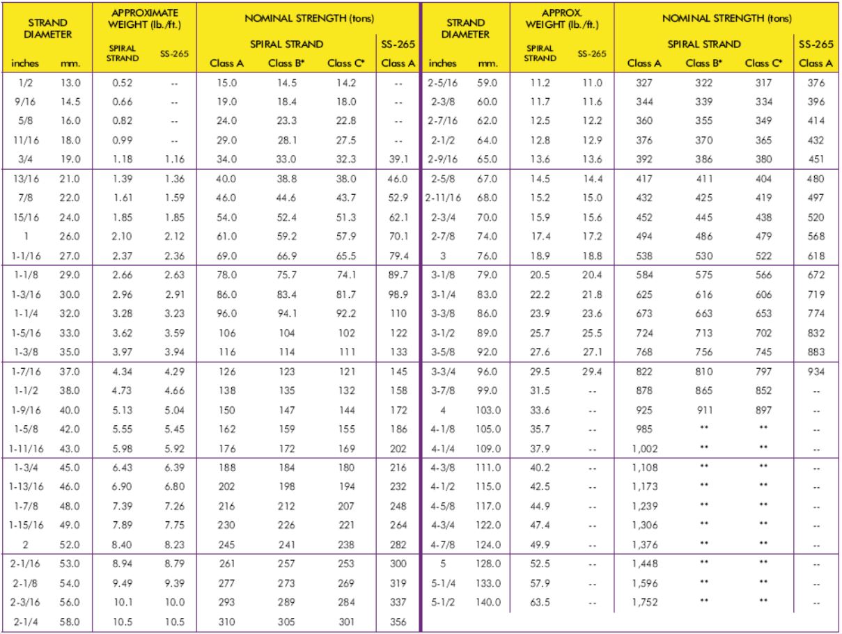
The following Table presents the Spiral Strand Wire Rope mechanical characteristics:
6.4.2.3 Synthetic Ropes:
Exploration and production in ultra deep water means that high strength lightweight ropes are desirable for mooring lines. Synthetic ropes provide the correct balance of strength, mass and diameter.
Typical fibre ropes are Polyester, Nylon, Aramid, HMPE or, polyurethane. The weight of the ropes in water is around zero allowing them to be close to neutrally buoyant or buoyant. The weight and elasticity properties make them more common for very deep water mooring applications.
Short term experience in real conditions results in a high safety factor being applied. Considerable change in axial stiffness after installation requires re-tensioning.
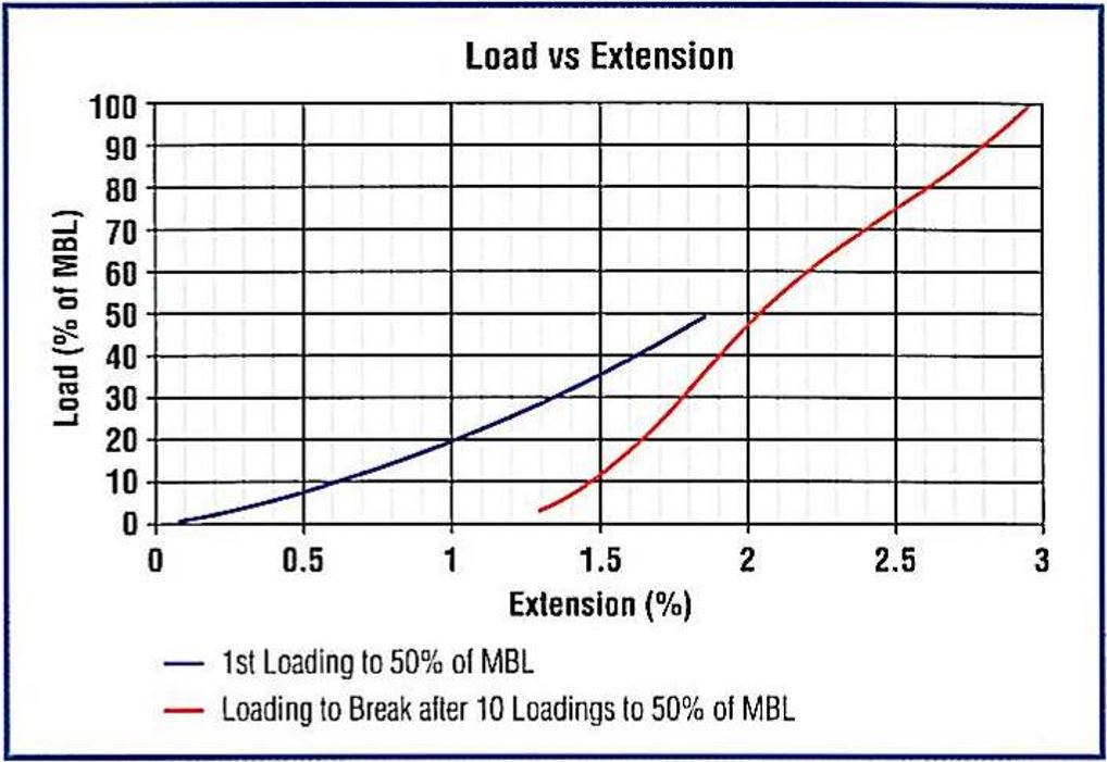
The basic elongation characteristics for the Superline Steelite Xcel (Dyneema Rope) of Marlow Ropes are shown in Figure 6.31, “Superline Steelite Xcel Elongation Plots (by Courtesy of Marlow Ropes)”:
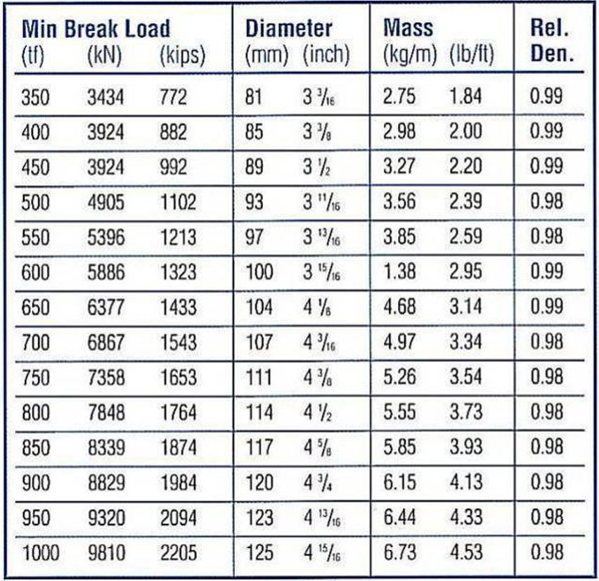
The following Table shows the relationship between the Minimum Breaking Load (MBL), linear mass, nominal diameter and the relative density for the Superline Steelite Xcel of Marlow Ropes.
Among the different types of fibre ropes, Polyester is the most field proven synthetic component for permanent deepwater mooring systems (good behaviour in extreme and fatigue).
6.4.3 Anchor
The anchor system design or evaluation methodology may be influenced by the following factors:
Site geophysical and soil geotechnical conditions.
Field plan development.
Anchor requirements, including vertical and horizontal load capacities, cyclic and ultimate conditions, installation methodology.
Design life, permanent, semi-permanent or temporary.
Anchor stability – limited allowable displacement under ultimate load – or roll stability under drag.
System inspection, re-usability or decommissioning requirements.
Cost implications / budgetary constraints.
The following sections describe the different available anchor systems:
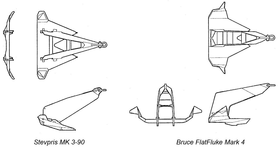
6.4.3.1 Fluke Anchor
Conventional fluke anchors are also known as drag embedment anchors. Horizontal holding capacity is generated in the main instalment direction by the embedment of the anchor in the ground.
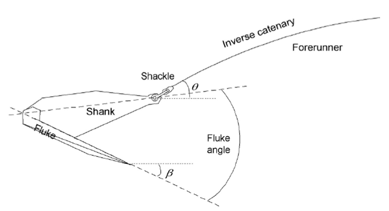
The main components of a fluke anchor (Figure 6.34, “Fluke Anchor Components”) are:
The shank.
The fluke.
The shackle.
The forerunner.
Stevpris MK 3-90 Bruce FlatFluke Mark 4

6.4.3.2 Vertical Loaded Anchor (VLA):
To further improvement the vertical load resistance needs in the taut line mooring configuration, the Vertical Loaded Anchor (VLA) technology have been introduced in recent years. VLA typically derives its capacity from a large bearing plate called a fluke. The slim anchor profile allows the VLA to be pushed into the seabed by means of a pile or small diameter suction caisson. During the pre-tension phase and design loading, force is applied to the plate through an anchor line attached to the fluke either by a rigid shank or bridle arrangement (Section 6.4.3.2, “Vertical Loaded Anchor (VLA):”). As the anchor is dragged horizontally, it cuts into the soil eventually becoming seated well below the mudline. Anchors designed specifically for significant vertical loading (VLAs) can be subsequently rotated such that the fluke is essentially perpendicular to the load applied by the anchor line.
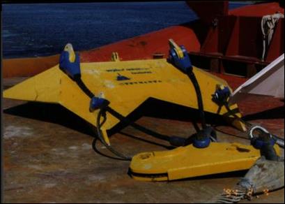
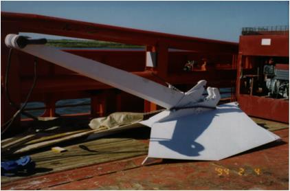
Drag Embedment Vertical Lift Anchors (VLA) System
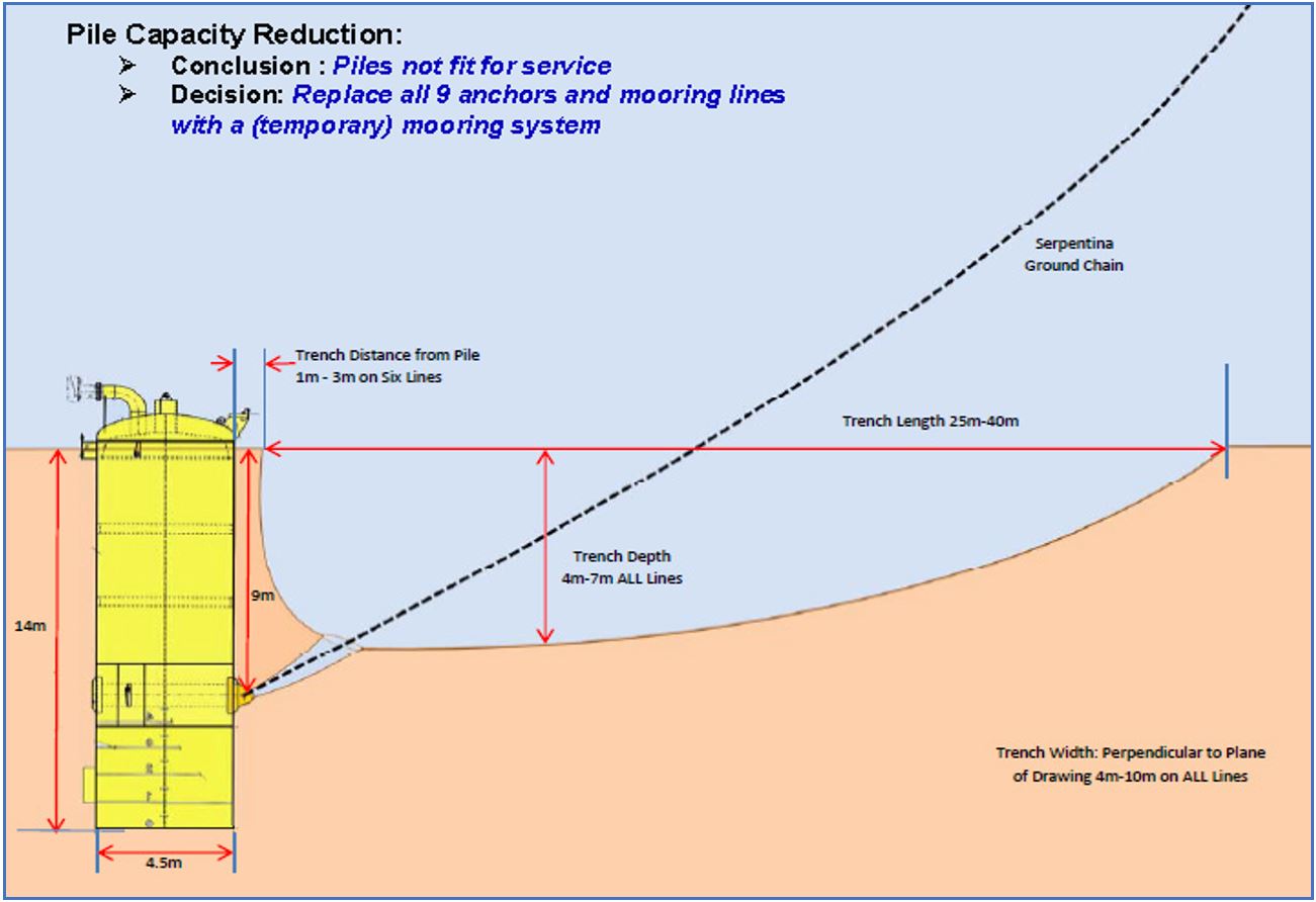
6.4.3.3 Suction Caisson Anchor
A suction caisson anchor is a large diameter cylinder open at the bottom end and closed at the top. Mooring loads are applied by an anchor line attached to the side of the caisson. The length to diameter ratio of the caisson is typically six or less. Once installed, the caisson acts much like a short rigid pile and is capable of resisting both lateral and axial load. The suction caisson gets its name from the fact that it is usually installed by applying under-pressure (“suction”) to its interior after it is allowed to penetrate under its own weight. Since the caisson’s interior is sealed from the seafloor by the soil, vertical loading creates an internal draw-down pressure which in turn mobilizes the end bearing resistance of the soil at the caisson tip.
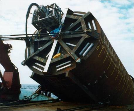
Seabed trenching has been observed in front of the suction piles of some mooring systems (ExxonMobil Serpentina FPSO, Dalia OLT Buoy,…). This phenomenon may reduce their geotechnical capacity up to a no more fit for service condition.
A means to delay this build up of trenching phenomenon could be to design a soft mooring system (catenary) instead of a semi-taut/taut one.
6.4.3.4 Jetted or Drilled Driven and Grouted Piles
Horizontal and vertical holding capacity is generated by conventional driven & grouted piles.
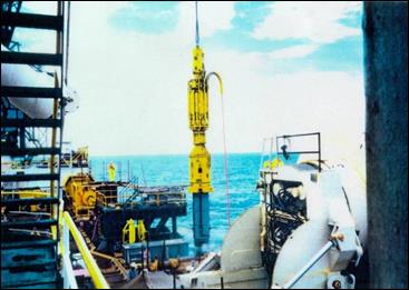
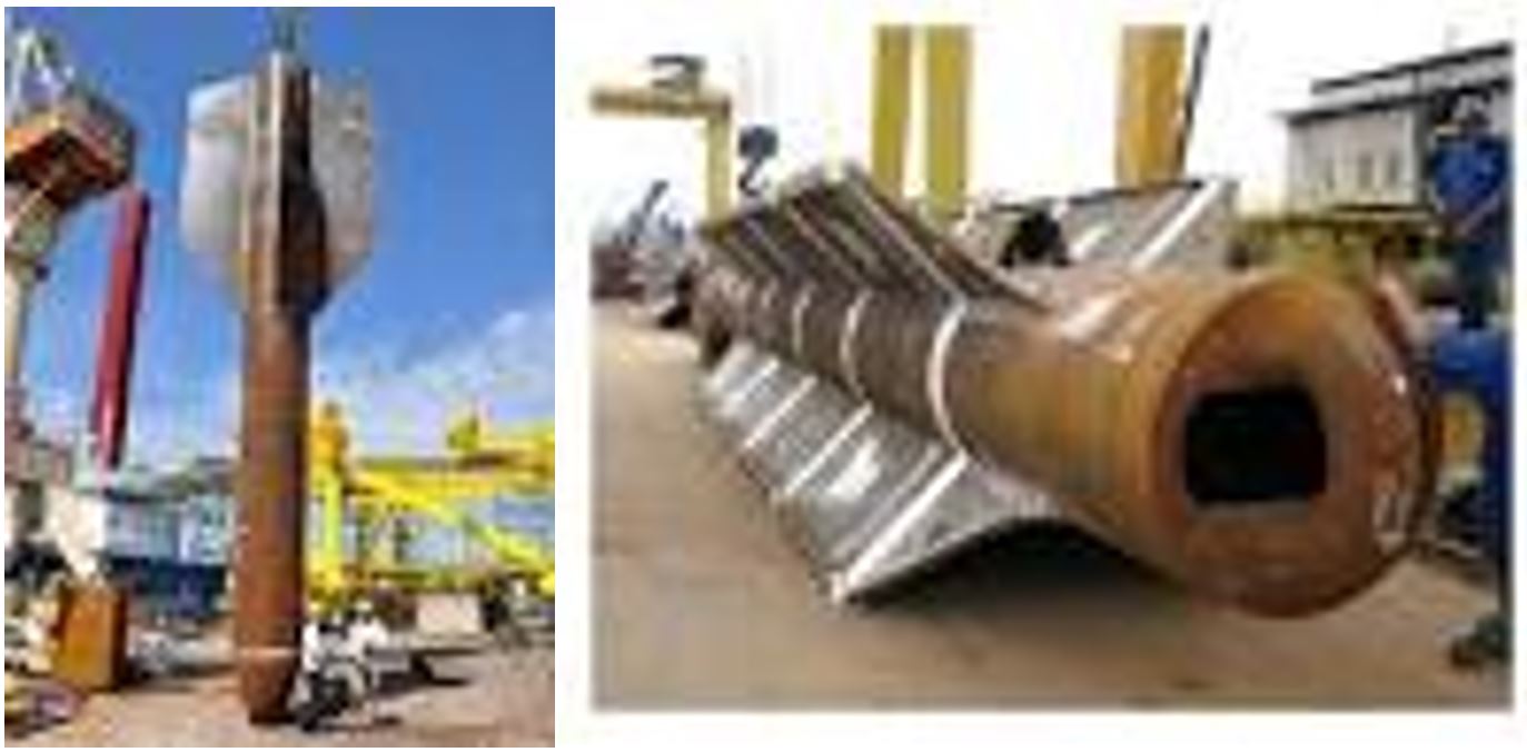
6.4.3.5 Torpedo anchors
Torpedo anchors are used as foundations for mooring deep-water offshore facilities, including risers and floating structures. They are cone-tipped cylindrical steel pipes ballasted with concrete and scrap metal and penetrate the seabed by the kinetic energy they acquire during free fall through the water. A mooring line is usually connected at the top of the anchor. The design of such anchors involves estimation of the embedment depth as well as short-term and long-term pullout capacities.
The first commercial application of torpedo anchors was conducted in the Campos Basin, offshore Brazil. To prepare it for installation, it should be first placed in a vertical position; after it is launched, the momentum caused by its own weight will drive it down into the soft seabed. The installation of the torpedo anchor does not require any external source of energy and it is a quick process requiring only one or two anchor-handling vessels and a limited use of ROVs (Remotely Operated Vehicles).
Due to the compact size of this kind of anchor as compared to other anchors, transportation to the site is easier and fabrication is more cost-effective. Further, no proof loading is required because of the very large kinetic energy made available through freefall, The other advantages include precise horizontal positioning, applicability for taut leg mooring and low sensitivity to increasing water depth. The holding capacity of the anchor is mainly determined by the penetration depth, which would depend on the impact velocity, penetration angle into the seabed, and the seabed soil properties. In order to precisely predict the holding capacity, the impact velocity has to be known in advance. Nevertheless, to calculate the impact velocity, the values of drag coefficient (CD) have to be precise. The torpedo anchor is generally launched from a high enough elevation above the seabed to acquire sufficient kinetic energy and reach a designated velocity so that it can penetrate into the target burial depth.
6.5 Dynamic Positioning Station Keeping System
The DP system is a well-know and reliable (computer controlled) thrusters systems to keep pipe-lay vessels or heavy lift barges on location during critical offshore construction activities. However such system has been seldom used in the past for FPS station keeping.
In the coming years, there will be a growing demand for FPSOs for ultra deep waters (greater than 2,000 meters) on a worldwide basis. One of the issues in the design will be the selection of the most cost-efficient station keeping system for the specified water depth and environmental conditions. In this case the technical and economical constraints associated with the use of conventional mooring systems may favour other concepts potentially more attractive and cost-efficient, such as a fully dynamically positioned FPSO. Additional cost benefit would be to dispose of the produced gas (from reservoir) to power the gas turbine-generator of the DP thrusters.
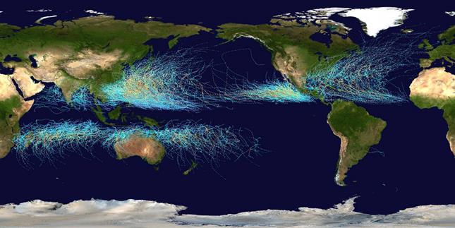
Dynamic Positioning station keeping system has also the major advantage to provide the ability to sail away from a hurricane. The destruction and damage of offshore installations in the recent history in Gulf of Mexico caused by hurricanes has again shown the vulnerability of the offshore industry in this region to these meteorological events.
In various other areas in the world the offshore industry is faced with these storms. Australia and China are other areas where these storms influence the offshore industry, see Figure 6.43, “Hurricanes & Typhoons Paths - Wordlwide”.
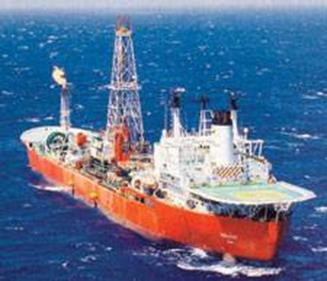
The FPSO Munin, operating on several fields in the China area, is equipped with dynamic positioning station keeping system and high propulsion power. At the Xijiang field, the Munin was stationed in full DP mode connected via an external turret (Figure 6.44, “FPSO Munin in Full DP Mode (Bluewater)”). The turret was designed to allow rapid disconnection from the riser system, providing the ability to sail away from a typhoon. This also provides the means of disconnecting from the riser system in case of a blackout or scheduled maintenance at a shipyard. The unit has experienced many typhoon approaching the area. In nine cases, the FPSO had to disconnect.
The successful application of FPSO Munin fitted with Dynamic Positioning (DP) and high propulsion power in the South China Sea have demonstrated the reliability of this station keeping system for areas faced with severe environmental conditions.
Other DP FPSOs are currently operating:
Seillean, offshore Brazil (Figure 6.45, “Seillean, a DP Class-2 FPSO operating in up to 2,000-m Water Depth (Brazil)”).
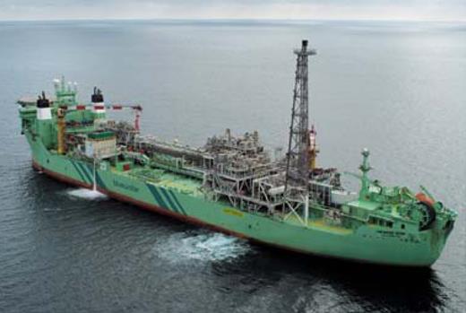
Haewene Brim, China Sea (Figure 6.46, “Haewene Brim DP FPSO (Bluewater)”).
CrystalOcean and CrystalSea (EPS).
Dynamic Producer (PIA-2) offshore Brazil.
ECO III offshore Mexico
TOISA PISCES (well testing) offshore Mexico.