
4 Pipelay methods
4.1 General
The physical scale of Deepwater pipeline installation possesses the biggest challenge to offshore contractors in being able to provide bigger and stronger equipment (& vessel) to handle installation at such depths (e.g. 3000 m) in an economic manner.
Important parameters in pipeline design are (1) steel material, (2) diameter and (3) wall thickness. The risers and pipeline systems are respectively described in the documents ref [32] & [33].
The pipeline material will be dictated by the produced fluid or gas corrosion properties and the diameter is chosen to suit particular maximum flow of the wells it is serving.
The wall thickness often needs to be chosen with particular care as the weight of pipe suspended directly from the lay vessel will influence the amount of tension required to hold the pipe during the laying operation. At such depth a few millimetres of additional pipe wall thickness can make the operation beyond existing vessel lay capabilities. Thicker wall pipe will also have a costly impact on material cost, transportation and installation, as longer offshore welding time will be required.
Several pipelay methods from a DP vessel (barges, ships, semi-submersibles) can be considered: S-Lay, J-Lay and Reel-Lay.
The following sections will further analyse the above pipe design considerations and the laying configuration constraints.
![[Tip]](tip.png) | Tip Click these links below for access to 3D resources: |
4.2 Pipeline Buckling Design
Designing the pipe to resist Deepwater hydrostatic pressure is the major factor which will affect the pipe wall thickness (refer to [26] & [33]).. Consideration must be given to both, (1) local buckling and (2) propagation buckling.
Local buckling can occur during offshore pipe lay operations when the pipe is under a combination of loads due to external hydrostatic pressure and bending moments, which can initiate a local buckle.
Alternatively such buckling damages or dents can occur if the lay tension is lost during the pipe-lay phase, as consequence of the vessel non control movement, failure of the pipe lay equipment, pipe/coating sliding, etc. In these cases, if the external pressure is high enough, the dent or local buckle may propagate along the pipeline in a phenomenon known as 'Propagation Buckling'.
This propagation buckling is driven solely by the water pressure, in which a local buckle in an offshore pipeline changes its geometry from a transverse dent to a longitudinal buckle and propagates along the pipeline, collapsing it along its length. Once initiated it will not stop until it either encounters an obstruction on the line or reaches shallower water where the external pressure will be less than the propagating pressure.
Since the propagation buckling pressure is much less than the local buckling pressure, the pipe design based on the propagation criteria will result in thicker wall pipe and the resulting tension can be very well beyond existing lay vessel capabilities and become an economic issue.
The alternative is to remain with the optimum wall thickness to resist local buckling collapse design criteria (to suit existing lay vessel capabilities) and to install buckle arrestors at suitable intervals. Should a propagation buckle unfortunately occur (i.e. loss of lay tension), then only a short section of line would require to be replaced. the alternative is also to lay pipeline flooded (typical for WI lines).
4.3 Deepwater Pipelay Method
4.3.1 General
Increasing water depths will exacerbate the problem areas, such as:
Top tension necessary to hold and control the pipe catenary
Pipeline initiation method and tension
Abandonment and recovery of the pipelines, considering accidental flooding
Touchdown point monitoring and survey
Pipe-lay out-of-straightness, impacting future pipe lateral buckling when in production
Economic need for lay speed
greater tensions during S lay and Steep S lay methods create horizontal forces that are difficult for DP systems to manage
4.3.2 S-Lay
Conventional S-lay is carried out from a purpose built moored barge and DP vessel with a stern stinger featuring an S-lay configuration. The lay barge allows the pipe to be welded, controlled and coated in a continuous horizontal production system based on different workstations (e.g. 5 welding stations, 1 NDT/repair station and 2 pipe-coating stations) to form a 'firing line'. Pipe can be assembled (welded) by stalk of 1 or 2 joints, of 12m each. This leads to a fast production process even when dealing with large diameter pipes (e.g. 42”-60”) typical lay rates from 2 km/day and up to 7 km/day (on occasion) can be achieved.
However, because the pipe is assembled in the horizontal position it needs to be laid off the back of the vessel in an S-shaped ‘double-catenary’ and supported by a stinger to prevent the pipe from buckling.
Because of the pipe departure angle at the stinger tip (30-40 degree range from horizontal, depending on water depth and pipe diameter), S-lay intrinsically requires much higher tensions (than J-lay) to control the pipe curvatures (see Section Section 4.5, “S-Lay versus J-Lay”). Furthermore the long lay back distance of pipe touch down point in Deepwater with S-lay is also problematic and restricts its ability to lay around a curve.
The practical water depth limit for a large, conventionally moored lay barge that uses the S-lay method is about 600m, based on a ratio of anchor line length to water depth of about five to one. S-Lay method by dynamically positioned lay barges is required for deeper installation.
Conventional S-lay method depth track records:
Saipem ‘Castoro Sei’ has performed S-lay installations:
32" submarine pipeline 516 km , from Libyan to Sicilian shore through Mediterranean sea in Max. Water depth 1,115m.
36" Offshore Gas Trasport Pipeline from Albania to Italy across the Adriatic sea in 820 m.
20" pipeline section (WoI-West of Ibiza p/l), from mainland Spain at Playa Devesa to Punta de Cala Gracio on Ibiza, 123km long with a maximum installed water depth of 995 m.
20" section (EoI-East of Ibiza p/l), from Ibiza landfall to Mallorca's San Juan de Dios thermal power station, 145 km long, with a maximum water depth of 719 m.
two sealines 26" sealines, 30 km. each from Calabria to Sicily in max W.D. 611 m.
26”diameter pipeline at a depth of 615 m in the Strait of Sicily.
Acergy ‘Piper’ has installed 1200km of 44”diameter pipeline between Nyhamna in northern Norway and Easington on the south east coast of England. The route includes crossing the Norwegian trench at water depths of 380m.
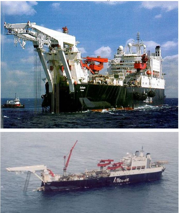
4.3.3 Steep S-Lay
To reduce these high tensions the stinger departure angle can be increased to 60°- 90° range (i.e. near vertical angle) in a configuration known as 'Steep S-lay'. This however means a longer and deeper stinger (e.g. Allseas Solitaire stinger is 140m long and reach 100m below the water surface) leading to more complex handling operation and greater weather sensitivity (see Section Section 6.3.3, “High Departure Angle Stinger (rigid pipe laying)”).
Furthermore the high pipe weight tension combined with the steep radius of curvature will introduce an elasto-plastic bending and a residual pipe strain in the 0.4% - 1% range (see Section Section 4.6, “Steep S-Lay Strain”).
Steep S-lay method depth track records:
Allseas ‘Lorelay’ deepest Steep S-lay has been recorded when laying the 12"diameter Flowline at a depth of 1650 m on BP Marlim (Gulf of Mexico).
Allseas Solitaire has established current deepest Steep S-lay installation of a 10”diameter pipeline at a depth of 2275 m on Enterprise MC920 (Gulf of Mexico).
4.3.4 J-Lay
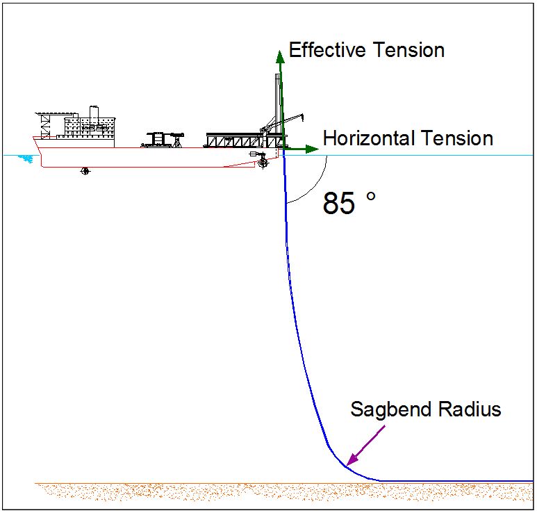
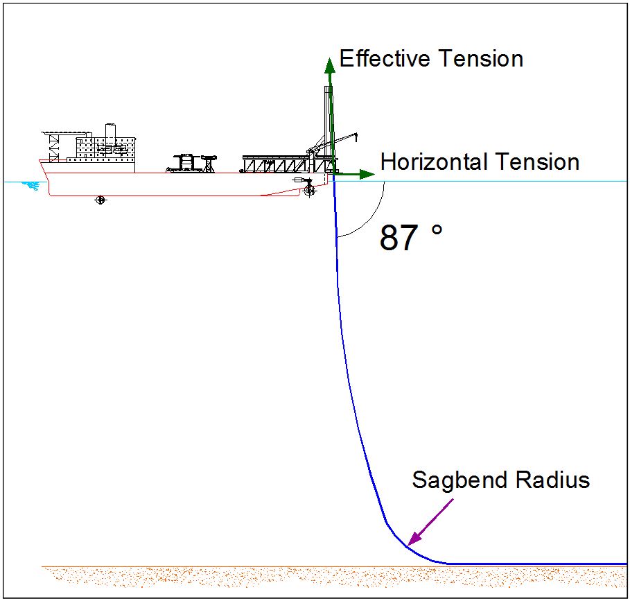
This is the third configuration for pipeline laying, where the pipe departs from the lay vessel at a vertical or near vertical angle (e.g. 70°-90°). There is no over-bend to be maintained as in the above cases. The pipe hangs in catenary and curves towards the horizontal as it approaches the seabed (i.e. sag bend radius).
A smaller lay tension is necessary to maintain a satisfactory curvature at the sag bend. To control the stresses and prevent buckling, the major part of the tension requirement is simply to hold the submerged weight of the pipe. The horizontal force required for station keeping is within the capability of most dynamic positioning systems.
Residual pipe axial tension laid by the J-lay method is significantly less than with the S-lay method (sees Sections Section 4.5, “S-Lay versus J-Lay” and Section 4.8, “Deepwater J-Lay Parameters (Rigid pipe, Flexible & Umbilical)”).
Since the pipe is departing from the vessel in the near vertical position, this implies that the welding should be done in the near vertical as well. In addition it is not practical to have a vertical 'firing line' as in the S-lay, the pipe is therefore assembled (welded) by stalk of 2, 4 or 6 joints at deck level (horizontal plan) prior to be upended (by means of loading arm) into the lay ramp for final welding to the laid string. A 6 joint stalk (e.g. 72m long approx.) is considered to be the current practical limit for up-righting (i.e. Heerema Balder J-lay equipment, Section 7.2, “Pipe Lay Vessels”).
The pre-fabricated stalk of joints is up-righted from the horizontal position to the vertical lay ramp, where it is welded at a single station. This makes the production process much slower than for S-lay. Typically, 1 km/day to 3 km/day can be achieved depending on the pipe diameter and wall thickness.
The pipe needs to be held (in the vertical position) while welding of the stalk joint is taking placed; three alternatives can be adopted: (1) tensioners, (2) pipe collars or (3) friction clamps.
J-lay method depth records:
Because the pipe lay (in 'J' configuration) is without residual strain, it is the preferred method for laying Steel Catenary Riser (SCR):
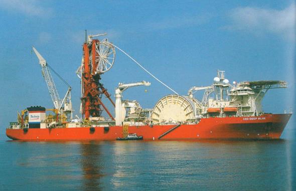
The current deepest J-lay of pipeline SCR (16”SCR) has been performed by Deep Blue (Technip) on the Na Kika project (Gulf of Mexico) at a depth of 1938m.
4.3.5 Reel-Lay
The fourth method for laying Deepwater pipelines is by the reel lay method. This pipe-lay technique can be considered as similar to the J-lay approach, with however a main difference as the pipe is continually fed down an adjustable lay ramp from a large storage reel mounted on the ship (see Section Section 4.7, “Reel-Lay Strain”).
Prefabricated pipe lengths (e.g. 500m - 1000 m) are pre-welded together and thereafter spooled onto the ship reel at an onshore fabrication yard (spool-base), thus minimising the offshore time or installation duration (weather window) required for pipe-lay operations. Typical lay speed of some 12 km/day can be achieved, however the ship limited in pipe carrying capacity would necessitate multiple trips between the offshore field and the spool-base to collect more pipe, or to replace the empty reel with a pre-loaded reel by means of heavy lift crane vessel. In this process, long pipeline (trunk-line) may require to be abandoned and recovered for subsequent pipe length jointing.
The pipe is departing from the vessel in the near vertical position (as for the J-lay) and the pipe load tension is controlled by both tensioners (mounted on the J-lay ramp) and the storage reel.
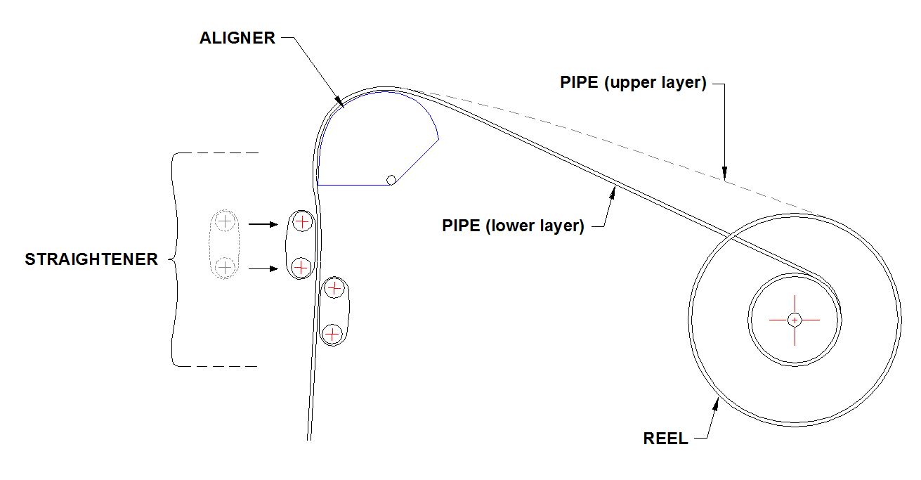
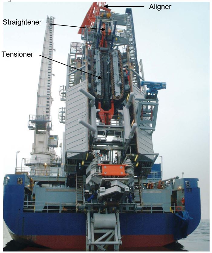
During pipelay operation, the pipe is un-spooled from the reel and guided via an aligner to a straightener on the lay ramp. The pipe then passes through the straightener, down the ramp, through the tensioners and over-boards the ship (see Section Section 4.7, “Reel-Lay Strain”).
The main advantage of the reel lay method are high lay speed (i.e. short offshore operation time) but requires a near onshore spool-base. The current reel lay method is limited in diameter (i.e. 4” to 18”diameter for rigid pipeline) and requires larger pipe thickness for reelability (i.e. OD/WT ratio in the range of 12 to 15).
The spooling and un-spooling process will introduce an elasto-plastic bending with maximum cumulative strain limit in order of 2 % - 5% ranges. However there should not be any residual strain (unlike the 'Steep S-lay') as the straightener will exert a reverse bending moment which would result in a near zero residual curvature (see Section Section 4.7, “Reel-Lay Strain”).
Some examples of pipelines installed by Reel-lay method:
The current deepest Reel-lay has been performed by Deep Blue (Technip) on Na Kika project (Gulf of Mexico):
Deepest rigid pipeline 16” by reel-lay: 7,568 ft (i.e. 2306m).
Deepest pipe-in-pipe 8”x12” by reel lay: 6,940 ft (i.e. 2115m).
4.3.6 Horizontal Reel-Lay
An alternative to the vertical Reel-Lay method is the Horizontal Reel-Lay. In this method, the reel or carousel is horizontally positioned on the lay vessel. Global Industries is the only known installation contractor to use this horizontal spooled technique to lay offshore pipeline.
This installation technique can be considered as similar to the reel-lay approach until the tensioners. Downstream the tensioners, as the pipe is horizontal, pipe is laid off the back of the vessel in an S-shaped catenary and supported by a stinger (i.e. similar to the Steep S-Lay).
During pipelay, the pipe is unspooled from the reel and guided via an aligner to a straightener. The pipe then passes through the straightener, through the tensioners and is supported by a stinger and be laid off the back of the vessel in an S-shaped catenary.
This installation method has been developed in order to perform Reel-Lay installation, using conventional S-lay barge. Horizontal Reel-Lay allows to achieve high lay speed (e.g. 12 km/day) with converted S-lay barge at a minimised cost (i.e. ‘”Firing Line” is replaced by carousel and straightener).
As the reel-lay method, the spooling and un-spooling process will introduce an elasto-plastic bending with maximum cumulative strain in order of 2 % - 5% ranges; however not in the same plan, e.g. pipe horizontal plan during spooling/un-spooling process, and pipe vertical plan at the stinger location.
However, as the Steep S-Lay method, the high pipe weight tension combined with the stinger radius will introduce an elasto-plastic bending and a residual pipe strain in the 0.3% - 1% range (see Section Section 4.6, “Steep S-Lay Strain”).
4.3.7 Deepwater Pipelay Method – Pros and Cons
This section aims to summarise the main advantages and main disadvantages of each pipelay method.
Table 4.1 - Deepwater Pipelay Method – Pros and Cons
Main Advantages | Main Disadvantages | ||
Steep S-Lay | Rigid Pipe |
i.e. conventional S-lay
| |
J-Lay | Rigid Pipe | ||
Vertical Reel-Lay | Rigid & Flexible Pipe |
| |
Horizontal Reel-Lay | Rigid & Flexible Pipe |
| |
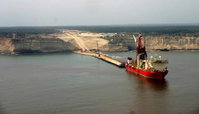
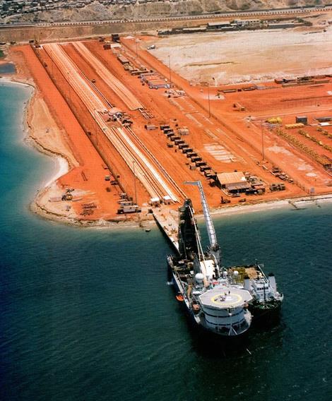
4.4 Spool Base Facilities
Reel-Lay method requires onshore spool-base facilities to assemble pipe stalks (e.g. 500 m to 1000 m). This section presents main spool base facility location and general arrangement:
Table 4.2 - Spool Bases Location
Spool Base | Owner | Country | Description |
Dande | Technip | Angola | |
Orkanger | Technip | Norway | Reeled pipe |
Evanton | Technip | Scotland | Reeled pipe |
Victoria | Technip | Brazil | Reeled pipe |
Mobile | Technip | Gulf of Mexico | |
Sonils | Subsea 7 | Angola | |
Wick | Subsea 7 | Scotland | Tow Bundle |
Leith | Subsea 7 | Scotland | Tow Bundle |
Luster | Subsea 7 | Norway | Reeled pipe |
Ubu | Subsea 7 | Brazil | Reeled pipe |
Impleside | Subsea 7 | Gulf of Mexico | Reeled pipe |
Vigra | Subsea 7 | Norway | Reeled pipe |
Carlyss | Global | Louisiana - USA | Reeled pipe |
Batam | Mc Dermott | Indonesia | Reeled pipe |
Gulfport | Mc Dermott | Gulf of Mexico | Reeled pipe |
EMB Gulen | EMAS | Norway | Reeled pipe |
The following figures present the general arrangement of a spool base:

4.5 S-Lay versus J-Lay
In deep water pipe-lay (> 1000m) the S-lay method is limited by the vessel DP capabilities (which have to counteract the pipe horizontal tension) and the pipe stress level at the stinger tip. In the same conditions the J-lay method has the following advantages:
Minimum horizontal tension to be controlled by the vessel DP system (thrusters power)
Lower pipe stress and bending strain level.
Better control of the J-lay sag-bend radius at touch-down zone (lower horizontal tension) and pipe routing.
4.6 Steep S-Lay Strain
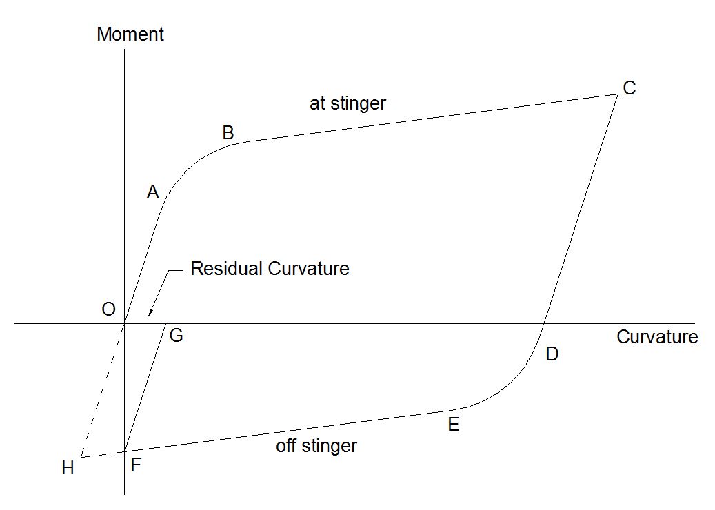
The following Figure 4.10, “Steep S-Lay moment-curvature relationship” illustrates the moment-curvature (i.e. pipe curvature is the inverse of the radius of curvature to which the pipe is bent) for elasto-plastic bending on a typical 'steep S' stinger.
As the pipe enters the stinger, the moment increases and the curvature initially increase proportionally, indicating an elastic beam bending response (straight line OA). Once the yield point is passed, the pipe response become non-linear and follows the path ABC, and plastic ovalisation occurs. As the bending moment is decreased (i.e. pipe has passed the stinger tip) the pipe recovers along the path CDEF and the ovalisation decreases. At this point the elastic recovery will result in a residual curvature (or strain) shown by point G, when the pipe will rest on the seabed.
To obtain a near zero residual strain, a reverse bend should be applied till point H is reached, prior to return to point O. However it is unpractical to install a straightener at the stinger tip.
4.7 Reel-Lay Strain
The following figure illustrates the stresses and strains during a completed reel lay cycle:
When the pipe is spooled onto the reel beyond the yield stress, the elasto-plastic strain follow the path OA
As the stress is decreased during the first un-spooled phase between the reel and the aligner, the pipe recovers along the path AB
When the pipe passes over the aligner curvature, a new stress-strain elasto-plastic deformation is experienced along the path BCD
A new stress relief is obtained when the pipe passes between the aligner and the straightener, as per the path DE
Finally a reverse bending is applied in the straightener (negative strain) until point F is reached, after which recovery should result in zero residual strain
As stated previously, the total cumulative strain experienced by the pipe may be in the 2%-5% range.
4.8 Deepwater J-Lay Parameters (Rigid pipe, Flexible & Umbilical)
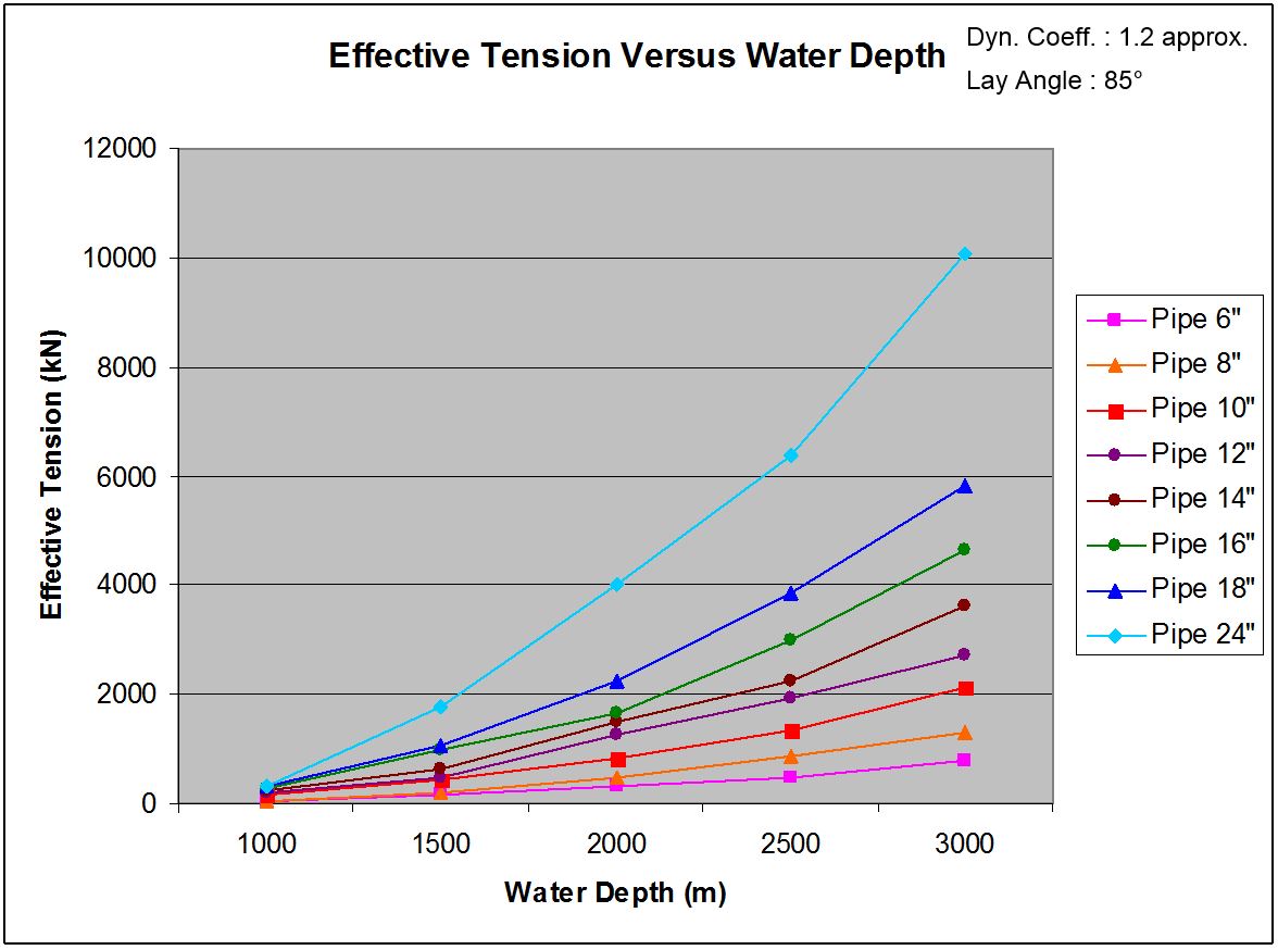
This section summarises the typical laying parameters for rigid pipes , flexible pipes and (steel tubes) umbilical for deep water depths from 1000m to 3000m.
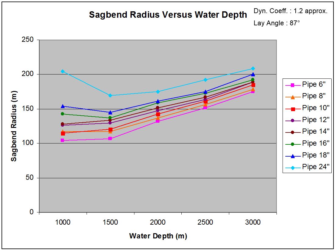
4.8.1 Rigid Pipe
Pipes ranging from 6" to 24" (see Table 4.3, “API Wall Thickness (mm)”) are designed for the considered water depth range based on the hydrostatic pressure / local buckling criteria Ref. (i.e. buckle arrestors could be used):
Table 4.3 - API Wall Thickness (mm)
Pipe | 1000m | 1500m | 2000m | 2500m | 3000m |
6"OD | 6.4 (6.7)(2) | 7.9 | 8.7 | 9.5 | 11 |
8"OD | 8.2 (11.0) | 9.5 (11.0) | 11.1 | 12.7 | 14.3 |
10"OD | 11.1 (11.1) | 12.7 | 14.3 | 15.9 | 18.3 |
12"OD | 12.7 (14.3) | 14.3 (14.3) | 17.5 | 19.1 | 20.6 |
14"OD | 14.3 (17.5) | 15.9 (17.5) | 19.1 | 20.6 | 23.8 |
16"OD | 15.9 (23.8) | 19.1 (23.8) | 20.6 (23.8) | 23.8 (23.8) | 27 |
18"OD | 17.5 (26.8) | 20.6 (26.8) | 23.8 (26.8) | 27 | 30.2 |
24"OD (3) | 22.2 | 27 | 31.8 | 34.9 | 39.7 |
![[Note]](note.png) | Note (1) Pipe Steel Grade X65 (i.e. SMYS= 448MPa; SMTS= 530MPa) (2) (Red value) is the minimum pipe wall thickness required taking into account the reel lay installation criteria (reel diameter: 16.5m, e.g. Technip Apache Vessel). Values are indicated only when dimensioning. (3) 24'' pipe currently out of reeling capability. |
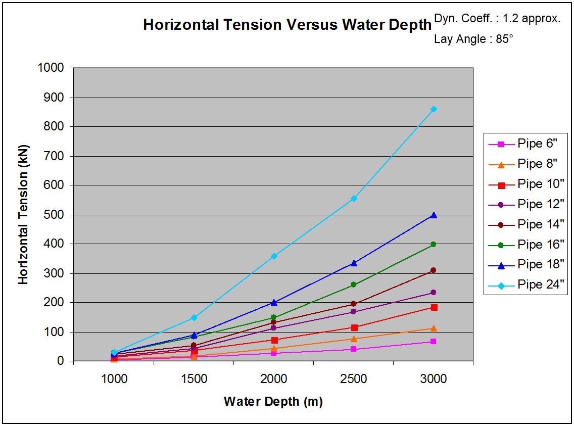
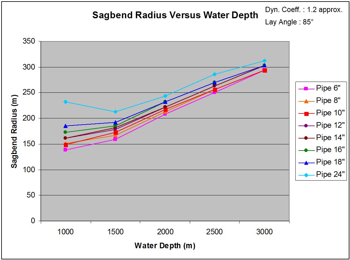
The following pipe effective tensions, horizontal tensions and pipe sag-bend radii have been determined for respectively 85° (see Table 4.4, “Rigid Pipe J-Lay Parameters (85° laying angle)”) and 87° (see Table 4.5, “Rigid Pipe J-Lay Parameters (87° laying angle)”) laying angle.
4.8.2 Flexible Lines
Vertical lay parameters have been defined for flexible lines ranging from 4" to 16" ID (see Table 4.6, “Flexible Lay Parameters (87° laying angle)”).
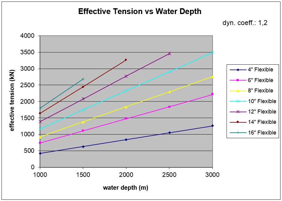
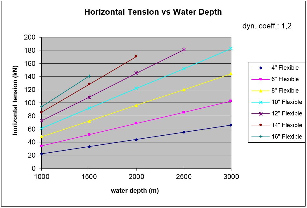
| Note
|
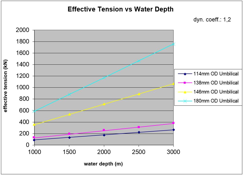
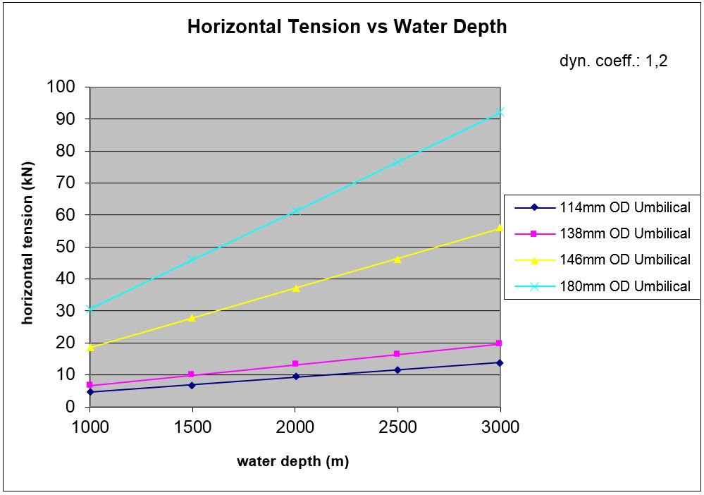
4.8.3 Umbilical Lines
Vertical lay parameters have been defined for steel tube umbilical ranging from 114mm to 180mm OD (see Table 4.7, “Umbilical Lay Parameters (87° laying angle)”).
4.9 Installation Method Limitations
The following Table 4.8, “Installation Methods and Limitations versus Sealine Technology” will summarize the limitations of each pipe technology versus the installation techniques:
Table 4.8 - Installation Methods and Limitations versus Sealine Technology
| |||||||||||||||||||||||
| |||||||||||||||||||||||


