
6 Installation and Laying Equipment Description
6.1 General
The equipment required on board the installation vessel for the laying of flexible lines, umbilical cables, rigid or reeled pipe are summarised in the following Table 6.1, “List of Product Storage Facility” and Table 6.2, “List of Installation Equipment”:
Table 6.1 - List of Product Storage Facility
STORAGE FACILITY | ||||||
|---|---|---|---|---|---|---|
Carousel | Dolly base | Vertical Powered Reel | Horizontal Powered Reel | Rack | ||
PRODUCT | Flexible line | X | X | X | X | |
Umbilical cable | X | X | X | X | ||
Reeled Pipe | X | X | ||||
Rigid pipe | X | X | X | |||
Table 6.2 - List of Installation Equipment
INSTALLATION EQUIPMENT | ||||||
|---|---|---|---|---|---|---|
Vertical Lay Spread | J-Lay Ramp & Tensioners | J-Lay Ramp & Hang-off Collar | Tensioners & High Departure Stinger | Tensioners & Lay chute | ||
PRODUCT | Flexible line | X | X | X | ||
Umbilical cable | X | X | X | |||
Reeled Pipe | X | X | ||||
Rigid pipe | X | X | X | |||
Typical load capacity and general description of the above equipment are presented in the following sections.
With regard to lifting equipment in Deepwater operations, two cases must be considered:
Surface or deck lift with crane.
Subsea lifting with adequate cable length and load capacities from a deck winch or crane.
As stated in Chapter 2, Deepwater Installation TasksChapter 2, the offshore topside heavy lift industry (see Appendix A, Deepwater Installation Vessels Summary Tables) is well provided and henceforth this topic does not require any further comments.
For subsea lift, holding a subsea structure weighing some 300T plus the lifting cable own weight of 130T (i.e. cable wire of OD 122mm, with linear weight of 65kg/m at 2000m water depth) will impose loads that a standard winch cannot cope with.
New handling equipment such as linear winches or capstan winches must be designed with the use of lighter cable (e.g. synthetic rope) with anti-twist property to fulfil the requirement of Deepwater lifting and lowering of subsea structures. (see Section 6.4, “Abandonment and Recovery Winch”)
6.2 Storage Equipment
6.2.1 Basket Storage Carousel
The basket storage carousel is a horizontal storing system designed to accommodate flexible line up to 16-inch and umbilical cable (see Figure 6.1, “Carousel on Technip Sunrise 2000 (Brazil)”).
It comprises a structure which will rotate on a vertical axis, and which is supported and run on typically double circular roller track.
Rotation is achieved by a chain transmission fixed to the outer periphery of the carousel base. There is also a central king pin for centralisation. The main components of a basket storage carousel system are listed below:
carousel structure
transmission drive
AC motor drive controller unit
supporting roller groups & king pin
spooling arm and chute system
control equipment
The basket storage carousel is equipped with an articulated spooling arm & chute system to correctly spool in the pipe during the load-out and extract the pipe from the basket during lay-down operations.
Typical technical specifications of a 2000T basket carousel system are described below:
2000T total product capacity
200T - 250T empty carousel weight
17m base or outside diameter
4m inside diameter
7m inside height
7m maximum product height
0-900m/hr laying speed
6.2.2 Horizontal Powered Reel
The horizontal powered reel is designed as a reel system dedicated to load and lay large quantities of flexibles, small diameter pipelines or umbilical, in particular integrated services umbilical (see Figure 6.2, “Umbilical Loading on Horizontal Powered Reel”).
The horizontal powered reel is also used to lay reeled rigid pipe from a reel lay vessel on which it is installed temporary or permanently (see Figure 6.3, “Global ‘Hercule’ Horizontal Powered Reel -”).
The horizontal powered reel comprises one rotating vertical axis reel around which the product is stored using laying ramp and straightener/spooler system which is mounted on the deck for the control of the spooling operation.
During spooling, the pipe string passes up the ramp and then wraps around the reel in a counter-clockwise direction. Before being wrapped around the reel, the pipe passes over an alignment shoe that adjusts vertically allowing the pipe to level wind onto the reel. The process is reversed during installation.
A straightener mounted aft of the aligner is used during installation of rigid lines (reeled pipe, rigid umbilical, integrated service/production umbilical) to remove any residual pipe curvature resulting from the reeling process. Note that the aligner is designed to bend the pipeline in the reverse direction before it enters the straightener. By reversing the pipe curvature, it ensures that the residual curvature of the pipe entering the straightener is constant.
Rotation of the reel supported by a base frame with a double circular roller track is achieved by a chain transmission fixed to the outer periphery of the lower reel flange. The replacement of the drive chain by a ‘rack & pinion’ gear system is an alternative solution to increase reel tension. There is also a central king pin for centralisation.
The system consists of the following main components:
base frame
horizontal reel structure
transmission drive
AC motor drive controller unit
supporting roller groups & king pin
straightener/spooler
control cabin
Typical technical specifications of a 1000T horizontal reel system are described below:
1000T total product capacity
170T-200T empty powered reel weight
12m base or outside diameter
5m inside diameter
5m inside height
6m external height
0-1800 m/hr loading speed, 0-900 m/hr laying speed
6.2.3 Vertical Powered Reel
There are two types of vertical powered reel depending on the product to be laid:
Flexible and umbilical powered reel
Rigid pipe powered reel
6.2.3.1 Flexible and Umbilical Powered Reel
The flexible and umbilical powered reel is a portable reel system designed for the purpose of installation or recovery of flexible pipelines and umbilicals (see Figure 6.4, “Flexible unloading from vertical powered reel”). The powered reel system has a specific product capacity and is designed to withstand the dynamic forces resulting from storm conditions while carrying this load.
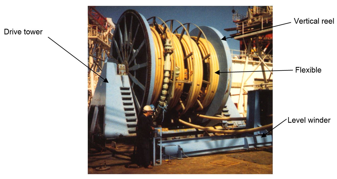
The powered reel can be split into two drive towers and the interchangeable drum. The lift beam is capable of lifting the base and reel together or separately. It is worth noting that this system can be used for spooling of small pipeline or coil tubing.
The powered reel system is composed of:
base frame
winch system
reel
AC motor drive controllers box
control equipment
level winder.
A typical 600T powered reel system main characteristics are as following:
Powered reel system empty weight 70T
Maximum product capacity: 600T
Total footprint area (including reel): 13m x 8.7m
Base frame footprint area: 13m x 5m
Reel dimensions : 14m flange diameter
4.8m hub diameter
Variable width
Torque ratings: 60T.m at 1 rpm
12T.m at 10 rpm
6.2.3.2 Rigid Pipe Powered Reel
The rigid pipe powered reel consists in one large reel of specific product capacity and permanently installed on board the reel-lay vessel (see Figure 6.5, “Technip ‘Deep Blue’ Vertical Powered Reel”).
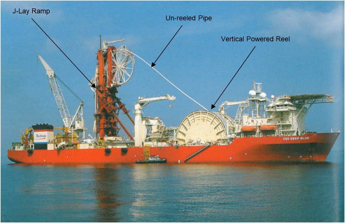
The pipe laying tension is entirely controlled by the tensioning system within the J-Lay ramp while the storage reel only takes the minimum back tension required for correct spooling/un-spooling of the pipe onto/off the reel.
When laying pipe, the reel is running in "drag mode", the reel torque is adjusted accordingly to the required back-tension.
When spooling on pipe, during ‘onshore’ load-out operation, the reel is running in traction mode and the reel torque is adjusted according to the required back tension.
A 2500T reel storage dimensions are as follows:
Flanges outside diameter 34m
Drum outside diameter 19m
Width 8m
Maximum pipe pay load 2500T
Storage volume 5113m3
Packing density 0.98Te/m3
Spool in/out speed 30m/mn at any layer
Spool back tension 50T
Drive system Hydraulic drive + rack & pinion
Reel bearing Shaft bearing
6.2.4 Dolly Base
The Dolly Base is used for the purpose of unreeling flexible or umbilical lines during laying operation (see Figure 6.6, “Dolly base”). In this mode a tensioner is required for maintaining the line tension.
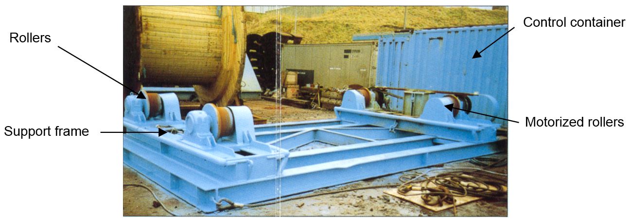
The dolly base could be used for spooling the flexible lines onto the reel. A level winder can be provided to control the fleet angle of the flexible during spooling.
It is composed of a base frame supporting four (4) rollers. The dolly base has a SWL capacity equal to reel plus product weight and can withstand the dynamic forces due to vessel motions. The dolly base system is composed of:
base framework
drive system
AC motor drive controllers box
control console
set of seafastening devices
lifting beam and sling set.
A typical 270T dolly bases features:
Total design loading (product plus reel) : 270T
Base frame footprint: 8.4m x 7.3m
Dolly base total weight: 30T
Line pull: 3T - 5T with a spooling speed of up to 1800 m/hr
6.3 Laying Equipment
6.3.1 Tensioner
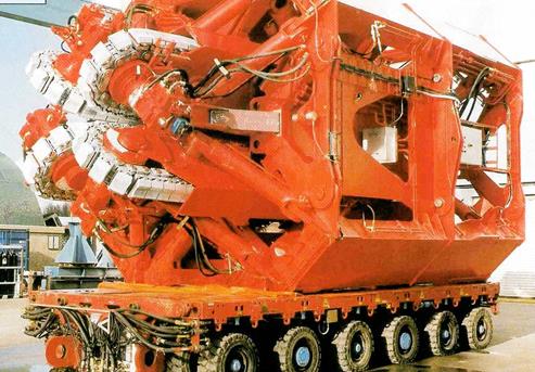
A typical tensioner designed for ‘hold back tension’ induced by weight of heavy products during installation phase, is composed of three or four track units mounted in a steel frame and driven by either electrical or hydraulic power system (see Figure 6.7, “60 tons Four Tracks Tensioner – Opening Tracks” and Figure 6.8, “275 tons Four Tracks Tensioner (Technip Deep Blue)”).
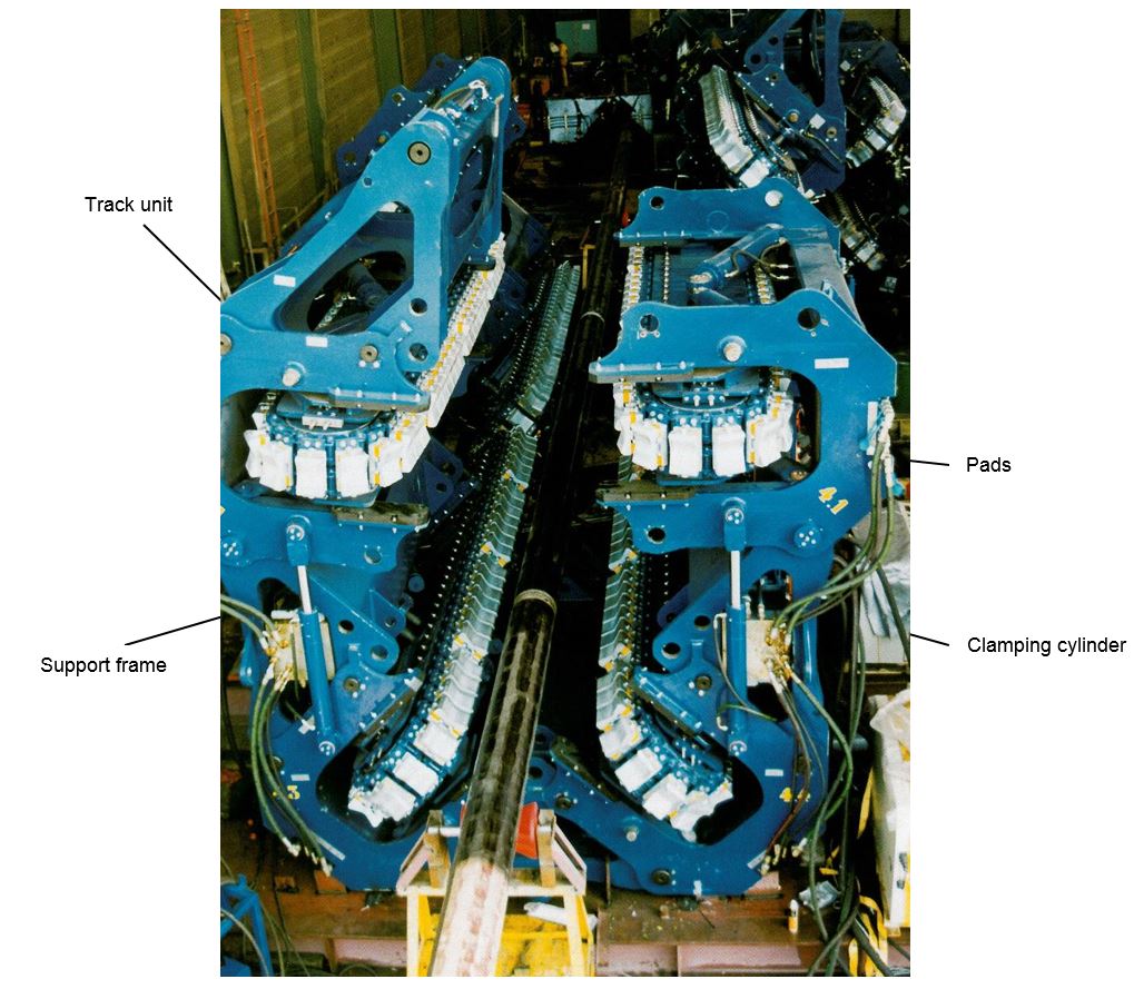
The track units, able to spread the clamping force over the circumference of the line, provide an even compression load over the full contact length. The current typical tensioner contact length is in the range of 1.2m to 3.5m (per track unit). Each of the track unit includes caterpillar chain and low friction chain rollers, and contains all tensioner functions which are:
Chain drive
Clamping function
Opening function to allow passage of end fittings, bracelet anodes, etc.
Load cell for tension monitoring
These track units are mounted in a closed frame, which can occasionally be opened to allow passage of larger objects.
The tensioner can be controlled either in speed mode or in tension mode. In the first case the tensioner maintains a certain speed which is dependent on the tension value. The tensioner can also be given a tension set-point. In this case the unit maintains a certain amount of tension independently of the speed.
The typical technical specifications of a 135 Te tensioner are as follows:
Dimensions 6.2m x 6.2m x 7.6m
Weight 105Te
Laying speed 0-15m/min at 125Te
7.5m/min at 135Te
6.3.2 Overboarding Chute
The minimum radius overboarding chute (i.e. 6m to 12m radius) aims to control the line curvature and to allow a safe overboarding of umbilicals (steel umbilical or integrated service umbilical) and flexible flowlines (see Figure 6.9, “Saipem ‘FDS’ Overboarding Chute”). Limitation of product laying top tension versus allowable installation radius and crushing loads.
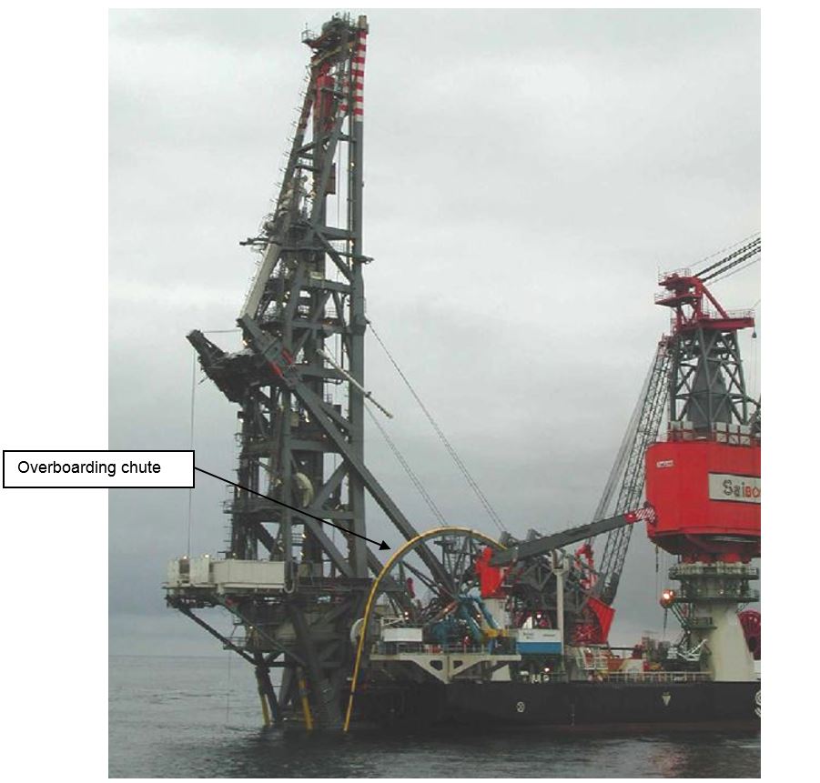
When fitted with a low friction chain, it permits safe transfer of lines from the horizontal position to the vertical position. The overboarding chute frame is fixed on the side or at the stern of the laying vessel.
6.3.3 High Departure Angle Stinger (rigid pipe laying)
The physical characteristics of this stinger are significantly different from stinger traditionally used in shallow to moderate water depths. The Deepwater stinger found mainly in steep S lay method provides (see Figure 6.10, “Allseas ‘Audacia’ Stinger for Steep S-lay Method”):
A near vertical departure angle for true J-lay with a low horizontal tension.
A fixed truss design rigidly connected to the barge, or sustain by an extended stinger support structure, to reduce pipe strains in the overbend.
3 or 4 pieces construction stinger with a removable tip section for vertical pipelay.
Closely spaced supports to limit pipe strains due to local bending on the supports.
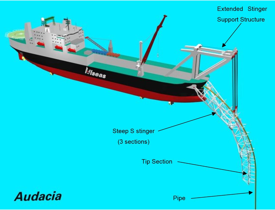
The stinger is rigidly attached to the lay barge or sustains by an extended stinger support structure, (instead of being hinged and free floating like a conventional S-lay stinger) because it must support the large pipe loads produced by the steep departure angle and high pipe tension required in deep waters.
The rigidly attached stinger also provides greater control of the pipe curvature in the overbend location. Because its position is fixed relative to the barge, it can use a smaller radius of curvature and still achieve the same actual maximum pipe strain in the overbend as the hinged floating stinger with a larger radius and greater length.
The high departure angle stinger is constructed in three or four pieces. Each part can be adjustable to obtain a stinger radius of 80m to 400m, depending on the water depth lay operation. Some stinger can be adjustable offshore, without assistance vessel. The stinger could reach 140m long and 100m below the water surface (Allseas ‘Solitaire’). This range of radii accomodates pipe diameters up to 60-inch.
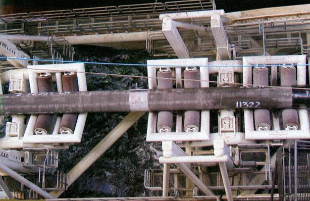
Along the length of the stinger, a series of roller boxes allow the pipeline to pass smoothly through the stinger towards the sea. Roller boxes have an average separation of 8m.
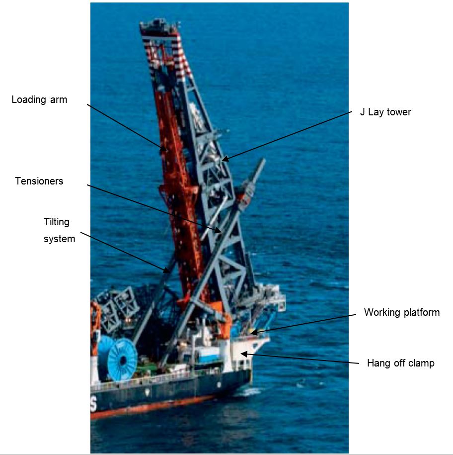
6.3.4 Rigid Pipe J-lay Ramp & Flexible vertical lay tower
The J-Lay ramp, installed on the ‘FDS’ lay vessel, is designed for the installation of rigid lines and flexible pipes in the near vertical position or J-Lay method (see Figure 6.12, “Saipem FDS J-lay Ramp”).
The main requirements for a typical 2000m water depth J-Lay ramp are listed below:
The ‘FDS’ J-Lay Ramp system includes the following main assemblies and components:
Tower structure used as a foundation to fixed the laying equipments, e.g. tensioners, hang-off clamp. The J-Lay tower is connected to the vessel main deck by means of a hinged connection at the lower end.
Tilting system served to raise the tower at a particular angle, e.g. from 45° to 96° in working conditions and to store the tower in lowest position (e.g. 12°) in survival conditions
Travelling assembly, running on a double guides and designed to lower pipe string handled by a hydraulic elevator upon completion of welding process. This assembly will also integrate the Internal Line-Up Clamp and X-Ray Tube with its umbilical winch
Tensioners mounted on sliding ramp will be moved from their storage position to pipeline lay axis for flexible lay operation
Retractable A&R sheave for abandonment and recovery of lines
Working platform located at the base of the J-Lay tower to support assembling station and welding equipment
Hang off clamp, positioned at the working platform, to hang the pipeline during welding operation
Active roller box system composed of upper and lower guiding roller sets to control pipe departure movements
Loading arm system to transfer pipe string from horizontal position at the firing line or storage area to various position of the J-lay tower. In addition the loading arm includes a line-up device for the performance of pipeline alignment prior to welding.
6.3.5 Reeled Pipe Ramp
The ‘Apache’ reeled pipe ramp (Figure 6-13) is capable of laying both rigid and flexible pipe including piggyback rigid pipe or umbilical. The system is also able to accommodate attachment and deployment of pipeline components such as flanges, anodes and buoyancy elements.
The pipelay system comprises a 30m ramp, which is elevated from 20° to 90°. The ramp can traverse 3 meters horizontally thereby negating the requirement for a spooling system on reel.
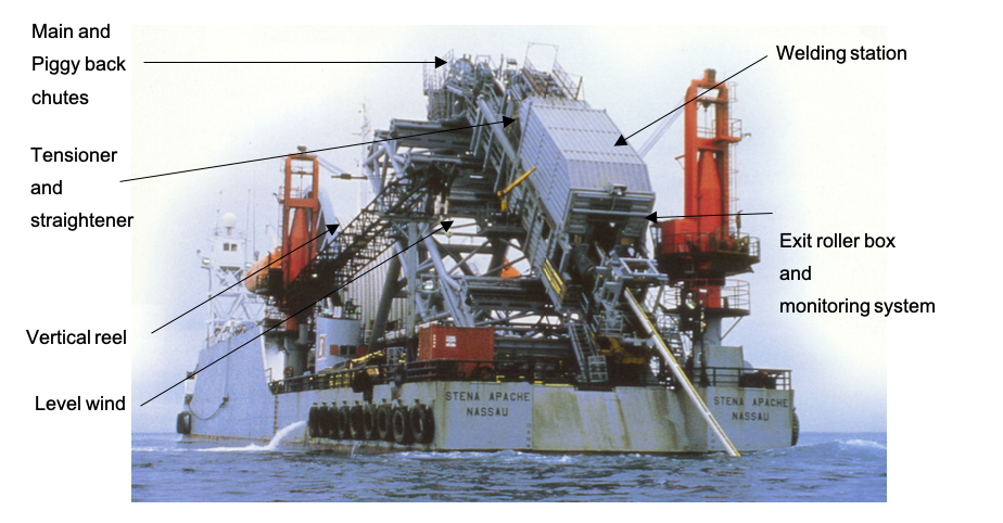
Situated on the ramp are:
Main chute
Piggy back chute
Main and Piggyback straightener
120Te tensioner
Pipe alignment cylinders
200Te hang-off clamp
A&R sheaves
Exit roller box
Exit monitoring system
The ramp pipelay system is controlled and operated from a central control station located in the Pipe Lay Control Cabin.
6.3.6 J-Lay Ramp
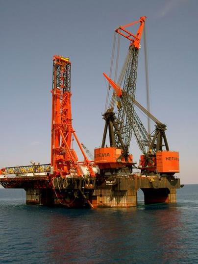
The Heerema J-lay system comprises 2 main modules: an upending ramp for the pre-assembled 72m pipe strings and a variable angle ramp/stinger (50°-90°) which contains the line-up tools, welding/inspection/coating station and pipe travelling block and clamps. The system is mounted at portside of the SSCV Balder (see Figure 6.14, “Heerema ‘Balder’ Rigid pipe J-lay ramp”).
The major system components of the J-lay ramp are described hereafter:
Upend ramp: This ramp upends the 72m long pipe strings from horizontal to the stinger angle by means of a tackle system located at the top of the ramp.
Ramp: This is hinged over the side of the vessel and its angle can vary from 50° to 90° degrees. It contains the travelling block (& head clamp), line-up tools, welding/inspection/coating station, hang-off clamp, and stinger with roller boxes.
Line-up tool: The external line up tool serves to take over the 72m pipe string from the pipe ramp after upending, then lower the pipe string to meet with the pipe line, and provide a provisional line-up between the pipe string and the pipe line. Final line up is achieved by means of an internal line-up tool.
Weld station: The weld station is located in the upper section of the hang-off clamp/stinger. It is mounted on a tilting platform to accommodate the J-lay range of inclinations. This platform provides floor space for the crew for line-up, welding and NDT. It also supports all equipment required for pipe line-up, re-beveling, welding and non-destructive testing. The station is weather protected.
Control cabin: The control cabin is located on the tilting platform.
Pipe departure angle monitoring system: For monitoring the stinger inclination and vessel heading with the direction of pipe departure, four rollers are provided at the very lower end of the stinger. They follow the pipe movements and provide information on pipe position.
Pipe departure support rollers: Series of rollers in a trumpet like arrangement is provided at the bottom end of the stinger.
6.3.7 J-lay Ramp using Hang-Off Collar
The following is a brief description of the major components of the four pipe strings J-lay system using hang-off collar (see Figure 6.15, “J-lay ramp using hang-off collar (J-Ray McDermott DB50)”):
A-frame and Foundation: This is a single piece module whose function is to provide support to the other major components of the J-lay system. Composed of tubular framing supported by three (3) large boxed girders, the A-frame and foundation extends over the starboard side of the lay vessel approximately 10m enabling the pipeline centerline to be located outboard of the lay vessel for J-lay operations.
Tower support structure: The tower support structure pins to padeyes located forward and aft of the stern and middle boxed girders in the foundation. Padeyes located on the tower support structure allow the J-lay system tower and stinger to be attached above and below the tower support structure respectively. A series of padeyes arranged vertically on the middle boxed foundation girder allow the tower support structure, tower and stinger acting as a unit to be adjusted over a range of 70 to 90 degrees relative to the horizontal.
Tower: Pinned at its base to the tower support structure, the tower provides the structural support for the major J-lay system pipe joint handling and pipeline lowering components. The tower provides guide rails for the raising and lowering of the strongback and travel block. Located at the base of the tower is the fully enclosed work area where all welding, NDT and field joint coating operations are conducted. Located on top of the 61m tower are a set of sheave assemblies facilitating the routing of the rigging utilized for pipeline abandonment and recovery operations.
Stinger: Pinned to the tower support structure, the stinger extends approximately 15m below the water surface and supports three (3) hydraulically operated, retractable full encirclement roller assemblies designed to support the upper portion of the pipeline during pipeline welding operations. Video cameras located adjacent to each stinger roller assembly assist the J-lay system operators to sequentially open and close each roller assembly in order to facilitate the passage of the J-lay collars and anodes during pipeline lowering operations. Five additional underwater video cameras located at the lower elevation of the stinger provide the means by which engineering personnel can visually observe and measure pipeline deflections required to maintain pipeline bending strains within allowable limits. The lower portion of the stinger is also designed to be retracted by extending two large hydraulic cylinders mounted to the upper (or fixed) portion of the stinger framing in order to facilitate pipeline abandonment and recovery operations
Ready rack: The ready rack, located immediately astern of the A-frame and foundation and centered on the pipeline centerline, provides guide rails for the strongback that tie-in by means of interchangeable tower angle transition rails to the strongback guide rails located in the tower. Four retractable horizontal roller assemblies located on the ready rack support each quadruple joint prior to being elevated into the tower for welding operations.
Strongback: Designed to travel along the guide rails located in the ready rack and tower by means of double roller assemblies located fore and aft, the strongback provides the means by which each quadruple joint is raised from the ready rack up into the tower for pipeline alignment and welding operations. Measuring approximately 51m, the strongback is equipped with four hydraulically operated multi-purpose pipe handling clamps designed to retrieve each quadruple joint while in the horizontal position from the ready rack and to assist in welding alignment operations when supporting quadruple joints in the vertical or near-vertical position in the tower.
Strongback lowering cylinders: They support the strongback while the strongback is in the vertical or near-vertical position and provide the means by which each quadruple joint is adjusted vertically for welding alignment operations.
Pedestal: The pedestal is located on two retractable support frames mounted on the tower support structure immediately below the floor of the work area. The pedestal of four vertical lugs which engage the underside of the J-lay collar flange, thereby providing the means by which the pipeline is supported below the field joint during welding, NDT and field joint coating operations. The pedestal is designed to be retracted away from the pipeline centerline in order to facilitate passage of the J-Lay collar and anodes during pipeline lowering operations.
Travel block: Designed to travel along the guide rails located in the tower, the travel block is an open face split block designed to engage the under side of the J-lay collar flange and is used to lower each quadruple joint onto the pedestal after welding and NDT operations are completed. The travel block houses two four-inch thick retractable slide plates which, when closed together under the flange of the J-lay collar, support the entire weight of the pipeline during lowering operations.
6.3.8 Flexible Vertical Laying System
The flexible vertical laying system is specifically designed to install large diameter flexible pipelines in deep waters (see Figure 6.16, “Vertical Laying System (Technip Constructor)”). The spread is installed at the stern (Technip ‘Sunrise 2000) or over a moonpool of the lay vessel, and is composed of the following stacked elements:
A working table, at deck level
Several modules of tensioner, stack-up within a support structure
An upper module supporting a pipe deflector (gutter), a service crane and the load transfer system (A & R Winch)
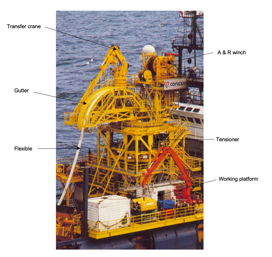
The working table is designed to support the full flexible catenary load and is composed of hydraulically operated movable parts and clamps the flexible end fitting. This allow for subsequent connection of flexible pipe length or special items such as end terminations, Riser pulling head, in a vertical position.
The system allows passage of intermediate connections and large assemblies through the moonpool. A safety collar is available at this level for securing the line tension at the working table in the event of tensioner break down.
The vertical laying spread is operated from the deck operation control room.
The technical specifications of a 270T flexible vertical laying system for 2000m water depth are presented hereunder:
Maximum pull: 270T
Maximum brake capacity 375T
Passage through tensioner 1200mm
Minimum flexible line diameter 80mm
Maximum flexible line diameter 600mm
Laying speed 0 to 16m/min
6.4 Abandonment and Recovery Winch
6.4.1 General
For Deepwater lowering and recovery operations (e.g. beyond 1500msw) the standard powered winches with steel wire cable are not adapted due to the high load requirement of some 500 tons capacity.
Three alternative A&R systems are being used with its own advantages and disadvantages:
linear traction winch with steel wire cable stored on a separated reel
capstan friction winch with cable stored on a separated reel
'flexible pipe follower' stored on dedicated reel/carousel and using existing flexible pipe tensioner device
6.4.2 Linear Traction Winch
The adequate steel wire length is stored on a large powered reel, with the load tension provided by a linear winch (see below figure). The linear winch features double jaw devices, one static and one moveable part activated by hydraulic rams providing a step-by-step displacement of the steel wire cable at each stroke.
This technique which can provide very high tension (more than 1000 tons) has a major drawback related to its very low lowering speed and is therefore used only for installation of very large subsea templates or foundation structures.
6.4.3 Capstan Friction Winch
As for the above, the steel wire cable is stored on a separated reel with the load tension provided by a double-drum capstan friction winch (see Figure 6.18, “Allseas ‘Solitaire’ - 250tons Capstan Winch with Storage Reel”).
This technique will provide sufficient abandonment and recovery speed (e.g. 900 m/h) with however a major drawback related to the residual torsion induced on the steel wire (passing through the double drum capstan winch) which would twist the cable as the lifted load is disconnected from it. Unless the steel wire is prevented from twisting, permanent damage will be experienced.
Capstan friction winches used in combination with steel wire of some 4"1/5 OD (250tons SWL) is currently limited to the water depth of 1000-1500m. Alternatively four capstan friction winches can be used in parallel to obtain the required 1000tons SWL at the target 3000m water depth, i.e. Allseas ‘Solitaire’ (Annex 01, Table 2).
Current traction winch development using synthetic rope (e.g. high modulus polyethylene 'Dyneema') could provide an economical solution for the 3000m water depth; however adequate friction between the synthetic rope and the capstan steel drums must be ensured.
HMPE line is lightweight, flexible, and buoyant. However, it has limited stretch/spring characteristics and low energy absorption. It has less resistance to shock loads than an equivalent BL wire rope. When twisted, HMPE rope suffers an average loss of 5% of MBL for each turn/meter. This is not a linear decrease. In extreme testing situations decreases of MBL up to 50% have been seen.
Synthetic rope has a major advantage in terms of weight, as its density is approximately 1.07, however there is concern with regards to (1) termination eye spliced, (2) tension fatigue and (3) tension capacity reduction due to creeping and ageing.
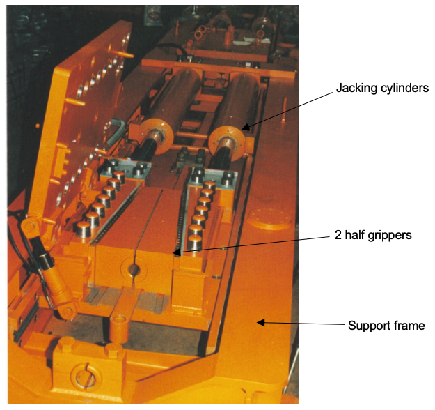
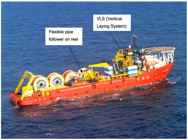
6.4.4 Flexible Pipe Follower
For Deepwater A&R operations down to 2500m, Technip has promoted a different technique known as the 'pipe follower' where a 6"OD flexible pipe is used with the existing tensioner system, to lower or recover pipeline (see Figure 6.19, ““Pipe Follower” using VLS tensioner”).
The main drawback is that this technique can be used only from a dedicated Deepwater vertical flexible lay spread.
6.5 Welding and Tie-in Techniques
6.5.1 General
The essential feature in offshore pipe laying is that economic pipe string production for a sufficient pipe-lay rate can be achieved only by partitioning the welding procedure in a series of single jobs at multiple welding stations using one or a combination of the following conventional welding processes:
Since the laying of pipelines in deep and ultra deep waters using the J-lay method requires single station welding, a long welding time would be needed to perform the entire weld at a single station using conventional techniques for pipe wall thickness up to 40mm. This problem has led to the development of a system of fast welding at a single station. Several welding processes (still at R&D stage) are being considered:
Electron beam welding
Flash butt welding
Radial friction welding
Laser welding
For small diameters (up to 10"-12"), the rates obtained with threaded pipes or by conventional welding method can be used at a pace that J-curve laying technique is economically feasible, e.g. 1.5 - 2.5km/d.
However, as regards the joining of heavy walled (1" to 2"), large diameter (12" to 36") pipes, the problem becomes totally different since the high rate of laying (1 joint every 15minutes) required for economic reasons can only be reached if the welding operation is carried out in less than 5 minutes. None of the conventional welding processes can produce this type of weld in such a short time.
6.5.2 Conventional Welding Technique
For conventional offshore or onshore pipe laying, manual arc welding by means of cellulose covered electrodes (SMAW) is fully field-proven (see Figure 6.20, “Manual Welding”).
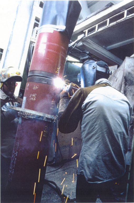
Mechanised shielded arc welding methods have been developed which have largely replaced manual welding with cellulose electrodes in offshore pipe laying because of improved weld quality and efficiency.
The estimated manual welding times for various pipe diameters are depicted in Table 6.3, “Manual Welding Time (typical)” for a constant D/t ratio of 20:
Table 6.3 - Manual Welding Time (typical)
PIPE OUTSIDE DIAMETER (inches) | WELD TIME (minutes) |
|---|---|
8.625 | 11 |
10.75 | 20 |
12.75 | 24 |
14.0 | 33 |
16.0 | 49 |
20.0 | 75 |
24.0 | 130 |
Note: Time estimated excludes inspection and coating and allows for increasing number of welders as diameter permits.
As shown, the time required increases rapidly for diameters greater than 16-inches. Material grade is also a factor in total welding time. Pipe wall thickness up to 1-inch for API 5L X65 (1.25-inch for X60 and 1.375 for X52) are expected to be suitable for welding with normal weld control procedures. Greater wall thickness will require specialised metallurgy control.
If the necessary pipe metallurgy cannot be achieved and post heat treatment becomes a requirement, a severe time penalty will be imposed. The heat must be maintained for a length of time sufficient to allow diffusion of hydrogen and elimination of ‘Martensite’ macro grain structures. Indicative of industry practice is one hour of post weld heat treatment per inch of wall thickness.
The estimated mechanised welding times for various pipe diameters are depicted in Table 6.4, “Mechanized Welding Time (typical)” for a constant D/t ratio of 20:
Table 6.4 - Mechanized Welding Time (typical)
PIPE OUTSIDE DIAMETER (inches) | WELD TIME (minutes) |
|---|---|
8.625 | 6 |
10.75 | 6 |
12.75 | 9 |
14.0 | 5 |
16.0 | 6 |
20.0 | 8 |
24.0 | 10 |
Note: Time estimated excludes inspection and coating and allows for increasing number of welding heads as diameter permits.
The mechanised welding system is an automatic orbital welding robot designed to produce high quality girth welds using either the single torch welding head or dual (or more) torch welding heads combined with the following welding process:
Some types of welding machine are presented hereafter:
Saturne 8T (Serimer):
This machine consists of 4 arms supporting each a dual torch welding head, travelling around the pipe, guided by a horseshoe-shaped ring (see Figure 6.21, “SATURNE 8T”). With its 8 welding torches, it is capable of high deposit rate in a narrow gap groove and is well adapted to weld thick and large diameter pipes (over 20”OD). The system is well suitable for pipeline in the range from 20” to 42” in diameter, and 16mm to 33mm in wall thickness.
The system is fully automatic:
The welding torches are accurately guided on the centre line of the groove,
The computer system drives all operations such as torch positioning, torch start-stop to the selected cycle sequence and other welding parameters which are pre-set for each pass.
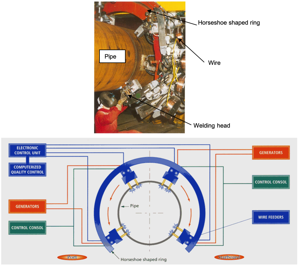
The operator has no influence over the welding operations. He only concentrates on positioning the machine, watching the molten pool and selecting the automatic cycle and general safety.
Saturnax (Serimer):
The welding system is composed of a self propelled carriage guided on a pre set ring around the joint and supporting a dual torch welding heads, and a fully integrated module with DC power sources and Electronic Control Units (see Figure 6.22, “Single Welding Head SATURNAX”).
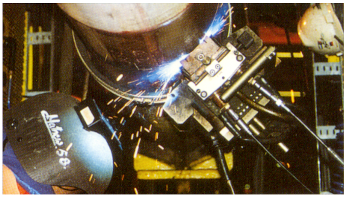
The light weight bugs carrying the welding torches can be handled easily by the operator. No need to touch the welding carriage when welding, they are fully automated except for the welding torch tracking relative to the joint bevel. This can be adjusted by remote control if necessary with a trigger on a small handset.
The electronic control units contain welding programs and safety devices. A Saturnax system with double dual torch welding heads is also available.
Single torch welding head using GTAW:
The welding system is composed of a self propelled carriage guided on a pre set ring around the joint and supporting a single torch welding head, and a fully integrated module with DC power sources and Electronic Control Units (see Figure 6.23, “GTAW Welding Head”).
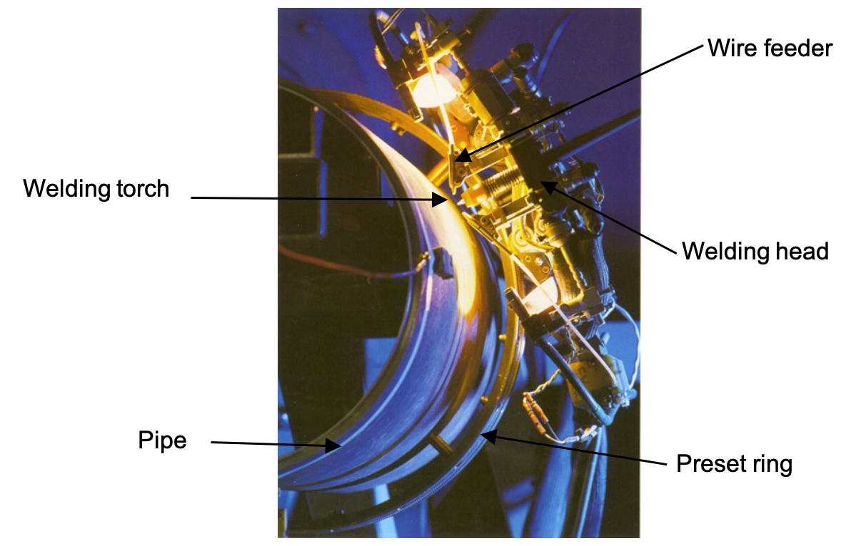
The welding head is computer controlled and is pre-programmed with the welding procedures for root, hot, fill and cap passes. The power supply is also a computer controlled with full control of pulse parameters, including pulse peak currents, pulse "on-time", pulse "off-time", pulse frequency, back ground current and average voltage as a function of wire speed.
Note: The welding procedure used for J-Lay is a narrow gap technique depositing an external root against a copper back-up. The copper back-up is integral to the internal line-up clamp. The design of the back-up bar is a circumferential row of 1-inch by 2-inch wide copper segments. Each segment has a spring mounted on each end so that the segment could pivot and adjust to any high low on the pipe inside diameter.
Mechanised welding procedure uses Ar-CO2 gas mixture as a shielding gas.
6.5.3 Electron Beam Welding (R&D status)
This method has already being applied in the aircraft, nuclear and automobile industries and had three main advantages:
Very short welding operations, since welds are made in a single run in the horizontal position, even for heavy thickness;
In these conditions it is possible to weld high yield strength steels without a post-weld heat treatment;
It is possible to fully automate the welding operation, thus increasing its Reliability.
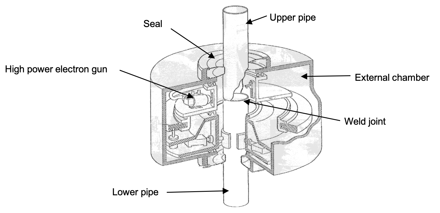
The electron beam welding process consists of two guns moving around the pipes to be welded in a chamber in a primary vacuum (10-2 Torr). The vacuum tightness is ensured on the inside and on the outside by seals placed directly on the pipes (see Figure 6.24, “Electron Beam Welding”).
A wide clearance seal made of reinforced elastomer has made possible the creation of a vacuum around the pipe in a matter of seconds and then maintained it at 10-2 Torr throughout the welding operation.
An accurate positioning of the beam on the joint is one of the requirements of electron beam welding because the very high power density required to produce the weld is obtained by concentrating a focal spot of 1 mm in diameter onto the joint. Therefore, the tolerances concerning the positioning of the beam on the joint, as well as the maximum permissible clearance between edges are below 1mm. This creates a problem when the pipe strings are long and large in diameter weighting over 10Te.
The machine containing electron guns is protected against the harmful effect of weathering and marine environment by a welding chamber divided into two parts: (1) an external chamber and (2) a pressure lock.
A primary vacuum is constantly maintained in the external chamber, thus limiting communication with the marine atmosphere to maintenance operations, which is very limited in number since the guns have long lifetime cathodes.
This external chamber in which a vacuum is always maintained houses the guns and nearly all mechanisms of the machine, thus protecting them against the harmful effect of the marine environment.
The pressure lock, however, is brought back to atmospheric pressure at every cycle.
The electron beam welding technique is capable to weld in 3 minutes a 1.25-inch thick, 24-inch pipe.
The adoption of this technology applying mobile high power electron guns working in a primary vacuum does nevertheless require that a certain number of problems are solved, for offshore application:
Adaptation of the process to the metallurgy of API steels,
Maintaining of a vacuum around the pipe during welding,
High Reliability of the generators in offshore and marine environment, e.g. humidity, salt water, dynamic motions, etc.
6.5.4 Flash Butt Welding (R&D status)
This method has been proven successful in welding land pipelines in the Soviet Union. Thousands of miles of pipelines with diameters up to 24-inch have been laid, and machines for laying up to 56-inch are available.
It is composed of a lower and upper frame structure. Supporting columns connects the frames. The lower chuck jaws are directly connected to the lower frame. The upper chuck jaws travel on a carriage saddle. A hydraulic press system supported by the upper frame controls the upper chuck jaws. Between the upper and the lower chuck jaws the inductive coils are arranged to swing out (see Figure 6.25, “Flash Butt Welding Machine (Prototype)”).
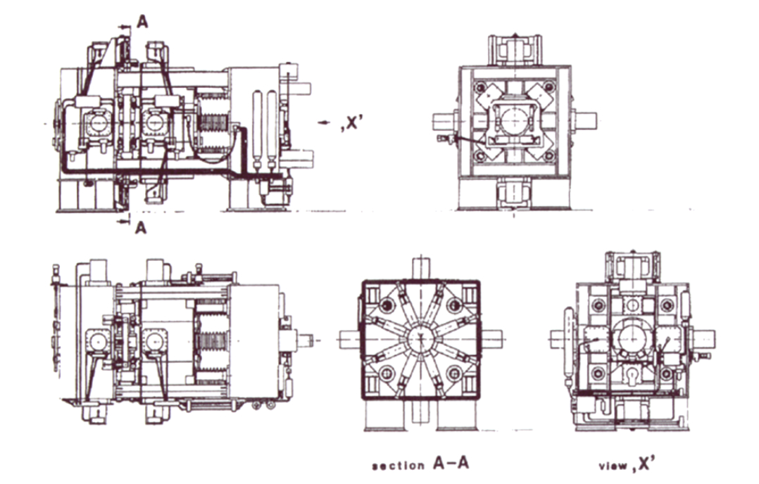
The technical data of the machine for welding X 60 pipes of 30" diameter and 40mm wall thickness is as follows:
Dimensions 7.1 m x 4.5 m x 4.7 m
Max welding cross section up to 100,000 mm2
Connection voltage 380V/50 Hz
Transformer capacity 3,380 kVA at 50% operating factor
Welding current max. 360 kA
Upsetting force max. 5,000 kN
Normalizing facility 1,600 kW, 150 – 350 Hz
The first phase of the flash butt welding method for pipes involves closing the gap between the two pipes while impressing high current and low voltage. At the points of contact the material is fused by the high current density and vaporises generating high pressure. By this the fused metal is ejected outward and the admission of oxygen to the weld is avoided. After a certain period of flashing the ends of the pipes are forced or upset together.
The success of a flash butt welding machine depends substantially on obtaining a uniform heating-up profile (as free of oxides as possible) at the moment of upsetting. This presupposed that sufficient electrical and mechanical powers are provided. The larger the cross sections welded together, the more difficult is establishing that condition. To meet these requirements, first an inductive preheating is connected in series before the flash butt welding. The pipe ends to be welded together are heated up to 950°C. Then in the flashing process sufficient welding temperature can be achieved in a very short period of time because of preheating.
An even current distribution over the entire pipe radius is also established by proportionate arrangement of several electrodes at the pipe within small distances from the transformers. The procedure of the flashing process is computer controlled so that it is reproducible concerning all important data: flashing speed, flashing acceleration, welding voltage, flashing current, etc. After achieving an optimal heat profile the upsetting process is brought into action, as determined by the upsetting force, speed and distance.
After the upsetting and the cooling down of the weld there is a coarse-grain structure in the weld because of flashing with high heat input in the weld area. That structure does not nearly have the ductility and deformation resistance quality of the unaffected material. Therefore an inductive normalising of the weld area is connected after cooling down to temperatures less than 300°C. By this provision a fine grain structure in the weld is achieved, meeting the requirements of offshore pipelining.
Having finished the post weld heat treatment, the rough edges inside and outside are sheared off. Inside a special cutting pig system is used, while outside a rotating milling cutter is used. The welding parameters of X52 pipe having dimensions 16-inch OD x 12.7mm wall thickness are as follows:
Welding voltage 8.6 V
Flashing current 17 kA
Flashing speed 0.4 mm/s
Flashing distance 10 mm
Upsetting current 50 kA
Upsetting force 600 kN
Upsetting speed 70 mm/s
Upsetting distance 20 mm
Preheating and postheating temperature 950 centigrades
6.5.5 Radial Friction Welding (R&D status)
Radial friction welding is a variant of conventional friction welding developed as a one-shot joining technique for pipelines.
This process is accomplished by butting together two pipes with bevelled ends in axial alignment which are held by clamps to prevent the pipes from rotating or moving apart (see Figure 6.26, “Flash Butt Welding Machine (Prototype)”).
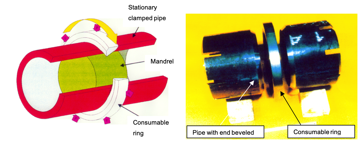
A heat resistant mandrel is expanded inside the pipe bore at the weld location. This mandrel serves to align the abutting pipes and to apply the radial welding pressure. The close fit of the mandrel prevents flash ingress into the bore leaving a smooth internal profile to the weld.
A solid ring of the same material as the pipe is machined on the inside diameter to a sharper angle than the angle between the bevelled ends of the abutting pipes. The ring is gripped with the jaws of the radial compression unit and rotation and compression is started so that the ring is progressively forced into the V-shaped preparation.
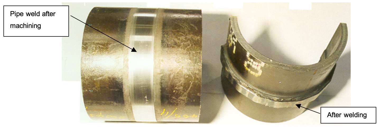
Friction heat sufficient for welding is produced and after a suitable metal displacement, rotation is ceased and the radial pressure maintained to consolidate the weld (see Figure 6.27, “Welding Sample”).
Radial friction welding is a solid phase joining process and is therefore suitable for a wide range of materials including many which are unsuitable for, or cannot be welded economically by fusion welding.
Radial friction welding machine covers flowlines in the size range from 6" to 12.75" O.D. 7.5mm to 30mm wall thickness, and is able to weld in cycle times of typically 20 seconds or less the following material types:
Radial friction welding would be well adapted to Flowline laying for the following main benefits:
It is an automated, machine tool based process which is highly repeatable and does not rely on operator skill
The welding speed is faster than arc fusion welding making single station operation economic.
Unlike conventional arc welding which relies heavily on welder skill and post weld non-destructive examination (NDE) for quality control, radial friction welding is an automated process which produces a solid phase weld i.e. without fusion of the pipes or consumable ring. The primary measure in assuring weld quality is therefore the monitoring of machine parameters during the weld cycle to ensure that settings such as speed, force and displacement have been kept within predetermined tolerances. The more traditional quality control checks can then be performed on the finished welds using visual and NDE techniques.
6.5.6 Mechanical Connectors
Two types of mechanical connectors are being promoted for faster pipeline laying operation:
Threaded and coupled connectors (e.g. Hydril)
“Snap and lock” device (e.g. Merlin and Thor connector from Oil States Industries and Wyman-Gordon respectively)
Subsea pipeline construction by lowering free-flooding 72m long string pipes has already been used in the North Sea to form the 24” BP Harding pipelines. A seabed hydraulic crawler connected the strings with «Merlin» snap and locks connectors.
However insufficient field proven records might prevent the mechanical connector technology to be adopted for pipe-lay operation.
6.6 Weld Inspection
6.6.1 Introduction
The inspection of butt welds in offshore pipeline production can be performed either by radiographic testing or ultrasonic testing. These two inspection techniques are described in the following sections.
6.6.2 Radiographic Testing
Conventional film radiography refers to the inspection process in which a film media is exposed to X or Gamma radiation, chemically developed to form an image, and then interpreted to help ascertain weld acceptability (see Figure 6.28, “Conventional Film Radiography Layout”).
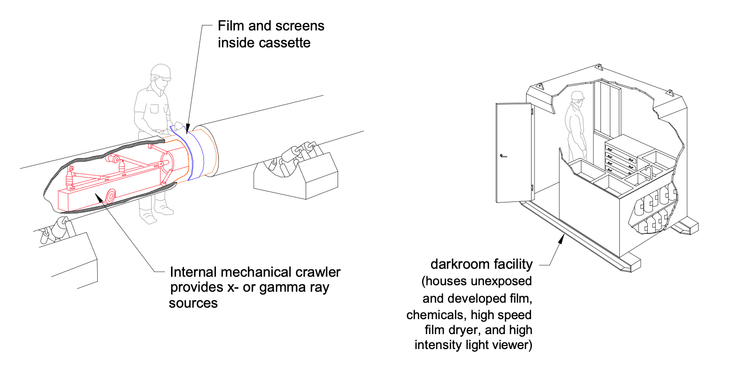
The radiation source is provided by an internal crawler when internal shots are made. The basic consideration in the use of radiographic testing is the qualification of the image against a specified standard. Using a given exposure geometry or technique, an image must be qualified before it is interpreted. Qualified images meet sensitivity and density requirements; they are also properly identified for purposes of traceability.
Sensitivity of the film is assured with the use of properly placed image quality indicators (IQI's). Placed next to the weld at specified increments, image quality indicators assure the inspector that image contrast sensitivity and resolution are adequate to visibly detect discontinuities in accordance with the governing standard. In the United States, the standard API 1104 or ASME hole penetrameter is the image quality indicator. "2%-2T" sensitivity is a common requirement of the film images. The penetrameters are chosen with regard to pipe wall thickness and weld reinforcement. "2%" refers to the thickness of the penetrameter as related to the thickness of the steel that the radiation must penetrate. When "2T" is specified, it is required that the "2T" hole in the penetrameter appears in the radiographic image.
In Europe, wire "DIN" image quality indicators are the standard. The ability to resolve wires of decreasing diameter on a given specimen relates directly to increasing image sensitivity. A lesser known image quality indicator is called the CERL IQI. It is composed of three parts; the first part is a flexible step wedge which is used to measure thickness sensitivity. The second and third part are metal wires which are closely spaced and dimensionally graded in geometric progression. The unsharpness of the image is measured by the least discernable spacing between two wires.
The density or relative darkness of an image is a second consideration in qualifying a radiograph. Density is measured on a scale called Hurter-Dreffield (H&D) units. Lighter film obtains lower valued H&D units while darker film obtains higher values. For film radiography, the range of acceptable density falls approximately between 1.8 and 4.0.
Most specifications require that identification of weld images appear on the radiograph so that the image can be traced back to the weld. Improper identification can be cause for rejection of the radiograph. Currently, lead numbers and flashing are the primary means for identifying radiographs.
The inspection cycle time is the time commencing with the arrival of the pipe at the inspection station and ending with the final interpretation decision on weld quality. In conventional film radiography, the following sequence of events occur during the cycle time:
Pipe stops at inspection station.
Radiation source is positioned at the weld location.
Film is wrapped around the joint.
Film exposure is made.
Film is transported to the dark room.
Film is developed
Film is dried.
Film is interpreted.
The minimum cycle time for conventional radiography on pipeline operations is four minutes to read film wet and four and one-half minutes to read film dry. These numbers represent the physical minimum times using hot chemicals and high speed dryers while not sacrificing image quality.
Mechanical and human operations are the main parameters which govern the operating Reliability of conventional radiographic systems. Operating personnel control such functions as exposure time, chemical temperatures, placement of film in cassettes, lead shielding, record keeping, and interpretation. Exposure time is currently regulated manually and controlled with a timer. Film development has become almost fully automated and less subject to human variability. Shielding must sometimes be replaced to avoid scratches appearing on the radiographic images. Film is interpreted on a high intensity light viewer screens.
For safety reason, the current total time of radiation exposure is calculated and safety areas are delimited so that personnel will not be overexposed. The total time for exposure at a given radiographic station on the laybarge during one day usually will not exceed two hours if 180 joints per day (4 minute cycle time) is assumed. This also assumes a 20 second exposure. Radiation safety zones are determined by marking off an area outside of which exposure will be limited to two milliroentgen per hour (2mR).
Note: The inside pipe diameter is a limitation in Radiographic testing using an internal crawler as radiation source. The minimum inside pipe diameter is 6-inch. For smaller pipe diameter, the radiation source is positioned on the weld joint in the opposite side from the film.
6.6.3 Ultrasonic Testing
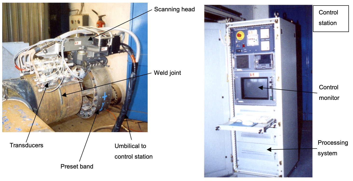
The orbital ultrasonic testing allows full circular weld coverage inspection in a single pass, with real time interpretation. The automated ultrasonic system for weld inspection consists of the following major components (see Figure 6.29, “Automated Ultrasonic Control System”):
32-Channel Ultrasonic Flaw Detector
Coupling Monitors
Data Acquisition Module
Temperature Control Module
Graphical User Interface
Data Storage (Optical Disk)
Graphical Output
Ultrasonic Scanning Head
Tandem or Focused Transducers
Every pipe size, wall thickness and welding procedure requires a different ultrasonic configuration.
Prior to the inspection process, a section of pipe is selected from project material for construction of the calibration standard, so that the standard has similar metallurgical properties and the same method of manufacture as the project pipe. The weld profile is analyzed and segregated into planes based on the geometry of the profile and desired resolution necessary for the acceptance criteria. A machine drawing is then generated providing reflectors in positions simulating the weld profile.
For each designated plane, a transducer angle is determined. Focal lengths and beam sizes are then plotted and optimised to the intended target. For each transducer angle, a velocity measurement is required to accurately determine wedge angles necessary to produce the desired refracted angle in the test material.
Each transducer in the transducer array is then applied to the calibration standard to confirm theoretical calculations for stand-off positioning. Optimized distance settings were then recorded and the transducers mounted in the ultrasonic scanner.
Prior to welding, a line is scribed on the pipe surface at a preset distance from the end preparation. This provided a reference point for application of the scanner band. Each transducer was then positioned at its operating distance away from the weld centerline on the calibration standard and adjusted to provide a peak signal from its target reflector in the transducer inspection zone. The peak response is then adjusted to 80% of full screen height for each channel. This is the primary reference level. Volumetric zones required additional gain to detect and characterize indications in their respective zones. A calibration scan is performed after each weld.
The ultrasonic scanner employs the same drive band used for welding, so that only a minor change is required for correct scanner positioning. Immediately after welding, a cooling apparatus was applied around the weld to reduce surface temperature to below 90°C, to protect against damage to the transducers caused by excessive heat. The scanner is then latched to band and the zero point set to the weld button. The operator initialized the inspection interface and proceeded with the one pass weld scan. Repair welds are examined in a similar fashion.
The ultrasonic system provides a proprietary software interface for correlation and display of the inspection data. The software is designed with a number of features which provided assistance to the operator for characterization, sizing and disposition of indications. These features included variable color spectrum ranges for rapid identification of both amplitude and transit distance. A data mapping module is included which combined both indication severity and position in a single display. The Graphical User Interface also included a convenient method for calculating defect lengths and electronic marking of these areas. Weld imperfection indications are evaluated by the ultrasonic operator based on the established acceptance criteria and immediately after scanning and weld disposition, copies of the ultrasonic inspection process are written to magnetic media along with a graphical print of the inspection run.
The average cycle time of ultrasonic inspection is 4 minutes for a 14-inch pipeline.
6.6.4 Remark
Methods of Non Destructive Testing are to be chosen with due regards to the conditions influencing the sensitivity of the methods. The method's ability to detect imperfections is to be considered for the material, joint geometry and welding process used.
Since the NDT methods differ in their limitations and/or sensitivities it may be required to combine two or more methods to ensure optimum probability of detection of harmful defects.
For detection of internal imperfections either ultrasonic and/or radiographic testing is to be used. Radiographic testing is generally preferred for detection of volume imperfections. Ultrasonic testing is generally preferred for detection of planar imperfections. Whenever determination of the imperfection height is necessary, ultrasonic testing is required.


