
5 Dynamic Positioning Equipment & Class
5.1 General
The DP system, encompassing all equipment, sub-systems, control, power, engines, thruster, etc, that directly or indirectly effects the position keeping ability of the vessel. All components in a DP system should be designed, constructed and tested in accordance with international standards set by the International Maritime Organization (IMO), the International Marine Contractor Association (IMCA), and the Marine Technical Society (MTS).
DP system can be designed with built-in Redundancy and Reliability to meet the standard requirements depending on the criticality of the task to be performed. There are 3 classes of DP Redundancy:
Class 1:
Non redundant equipment. Not suitable for E & P operations.
Class 2:
For DP equipment class 2, loss of position shall not occur from a single fault of an active component or system such as generators, thruster, switchboards, remote controlled valves, etc, or from a single inadvertent act by any person on board the DP vessel (but may occur after failure of a static component such as cables, piping, manual valves, etc.).
Class 3:
For DP equipment class 3, loss of position should not occur from any single failure (as for DP class 2 above) including any static component, and a completely burnt fire sub-division or flood watertight compartment.
For equipment class 2 and 3, Redundancy of all active components is required.
The minimum requirements of a DP system is defined in the document Ref..
The following sections define the basic and minimum requirements of the DP system.
5.2 DP Functional Requirement
5.2.1 Introduction
A fully operational dynamic positioning system shall reliably keep a vessel in pre-determined positions or tracks, such that the maximum excursion from vessel motions (e.g. surge, sway, yaw) and position control system accuracy shall be less than the critical excursion for the work being performed:
when working alongside other vessel or nearby structures (fixed or floating)
during subsea structure installation
during laying operation while providing a steady tension on product
during connection of subsea components/structures
during remote operated vehicle interventions
The DP systems comprise three areas defined as Power, Control and References:
Power can be sub-divided into power generation, distribution and consumption.
Control refers to an automatic power management system and the position control system.
References are essentially sensors giving position, environmental and vessel attitude information (e.g. roll, pitch, heave, heading, etc).
Redundant components and systems must be immediately available and with such capacity that the DP operation can be continued for such a period that the work in progress can be suspended safely.
5.2.2 Power System
The power system must have an adequate response time to power demand changes.
The power available for position keeping must be sufficient to maintain the vessel in position after worst case failure defined according to equipment class (refer also to section Section 5.4, “Safety Requirement” Safety Requirement for definition of 'worst case failure').
Utilities supporting power generation systems e.g. cooling water, fuel oil, lubricating oil must be arranged so that their failure consequences do not result in a loss of position.
Power management is essential on all DP vessels. DP vessels which use substantial amounts of power for other equipment (than thrusters) such as cranes, lay equipment, accommodation, pumps, etc., must have the possibility to shed load to maintain power to thrusters.
The electrical power distribution to thrusters is usually the aspect which determines the worst case failure mode. The control system must maintain enough power to give time to safely cease any operation for which position is critically important.
5.2.3. Thruster System
The thruster system should provide adequate thrust in longitudinal and lateral directions, and provide yawing moment for heading control.
The thruster units should be arranged to give, as far as possible, a balanced configuration even after the worst case failure.
A fail safe design must avoid a thruster control fault that results in uncontrolled thrust which can destabilise the whole system.
The following figure presents 360° azimuth thrusters types:
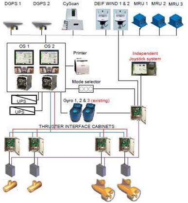
5.2.3 DP References and Control System
5.2.3.1 References
The position references have two functions; these are to provide (a) stable position information and (b) sufficiently accurate positioning data for the work being carried out.
For DP operations a minimum of three (3) independent references should be on line and of various types (e.g. DGPS, hydro-acoustic, radio or surface positioning) when working in close proximity of an offshore installation at least one of the selected reference systems must be of the Relative type. See for further detail.
When using similar reference sensors, they should be checked for complete Redundancy and without common failure modes.
The position reference systems on-line to the DP control should provide the DP operator with information to assist with decision making about individual reference system performance and malfunction.
Typical reference accuracy are summarised as follows:
5.2.3.2 Control System
The DP control system should provide adequate information to operators such that any change of status due to weather, equipment malfunction, or operator action shall be clearly indicated in the DP control room where corrective action is possible.
For product laying, the tension control equipment, must be considered as part of the position control system, and designed with the same philosophy and level of Redundancy to achieve a balanced vessel design.
To assist the DP operator, the control system should have a continuous analysis function checking that in terms of thruster and power the vessel can maintain position after the worst case failure mode.
5.2.3.3 System arrangement
The minimum requirements for DP equipment class system and arrangement are summarised in the following table :
5.3 DP Capability Definition (& Plots)
For each dedicated Installation Vessel a ship theoretical Capability plot must be produced, all in accordance with IMCA M 140, Specification for DP Capability plot for the following cases (see Figure 5.3, “DP Footprint”):
all thrusters operational with 100 % maximum effective thrust
all thrusters, except the most effective thruster failure
the maximum number of thrusters that could be operational after the worst case failure
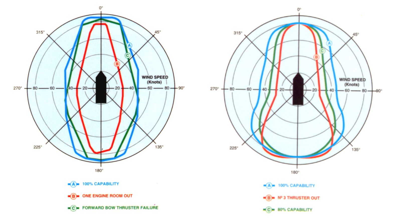
The above should be presented in polar plot form for various current speeds, i.e. 0, 1, 2 and 3 knots, co-incident with wind and associated wave loads from a fully developed sea.
A realistic allowance shall be made for thrust losses from, interaction, tunnel length, control system response, etc.
The purpose is to provide the DP operators with information so that they can assess whether safe working limits have been exceeded from intact power and thrust usage.
For product laying operations, the DP Capability plot shall be provided after the subtraction of the mean tension required for the highest pipe tension load combination (of heaviest pipe, deepest water, etc).
5.4 Safety Requirement
5.4.1 Introduction
DP safe working limits must be determined for each geographical location and type of task to be performed.
As a minimum, two types of risk assessment shall be performed :
5.4.2 DP System FMECA
When working closed to a fixed structure (e.g. FPSO) i.e. within the 500m safety zone, the environmental limits (i.e. wind, waves, current, respective headings), where the DP vessel can maintain position after the worst case failure that are known to be possible, must be defined.
This worst case failure is to be identified from a formal FMECA study, where all possible failure modes and effects are considered; to ensure that after the worst case failure, the vessel has sufficient capability to remain on position within safe limits from the FPSO (or other structures).
The FMECA study is to be supported by a complete set of proving trials verifying the findings of the study. See [24] for further details of trials requirements.
5.4.3 Hazardous Operation Analysis
In addition to the above formal DP vessel FMECA study, each location and task require documentation that further specifies any additional constraints in the form of HAZOP/HAZID risk analysis based on pre-established operation procedures (loading, transportation, laying, lifting, installation, testing, etc).
The principle here is that each task is given individual consideration prior to its being performed.
The defined operating limits are to be documented in Critical Activity Mode of Operation (CAMO) and Task Appropriate Mode of Operation (TAMO) documents. These documents are to be available and understood by all DP operators.
For product laying, the DP safe working limits must take into account:
the consequences of sudden failure of the tension load (e.g. tensioner failure)
limits of heading capability in beam environmental conditions


