
2 Interface requirement
2.1 General
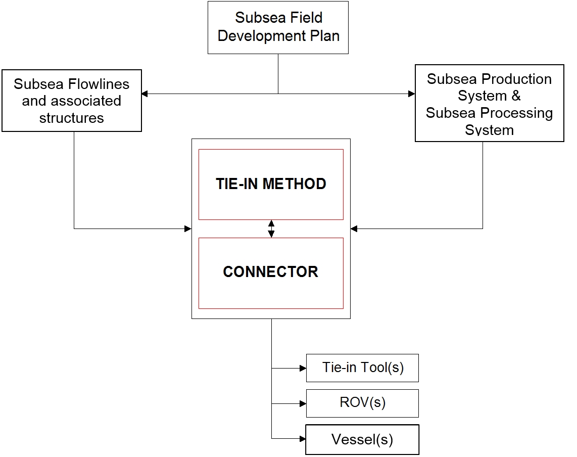
The following chart depicts the main interfaces of a tie-in operation, which are then further explained in the following sub-sections.
This clearly shows the importance of an early integration of the tie-in method/connector system selection into the overall Project Plan as they impact and interfere with the subsea architecture (e.g. wells, manifolds) and flow-line designs and tie-in vessel selection.
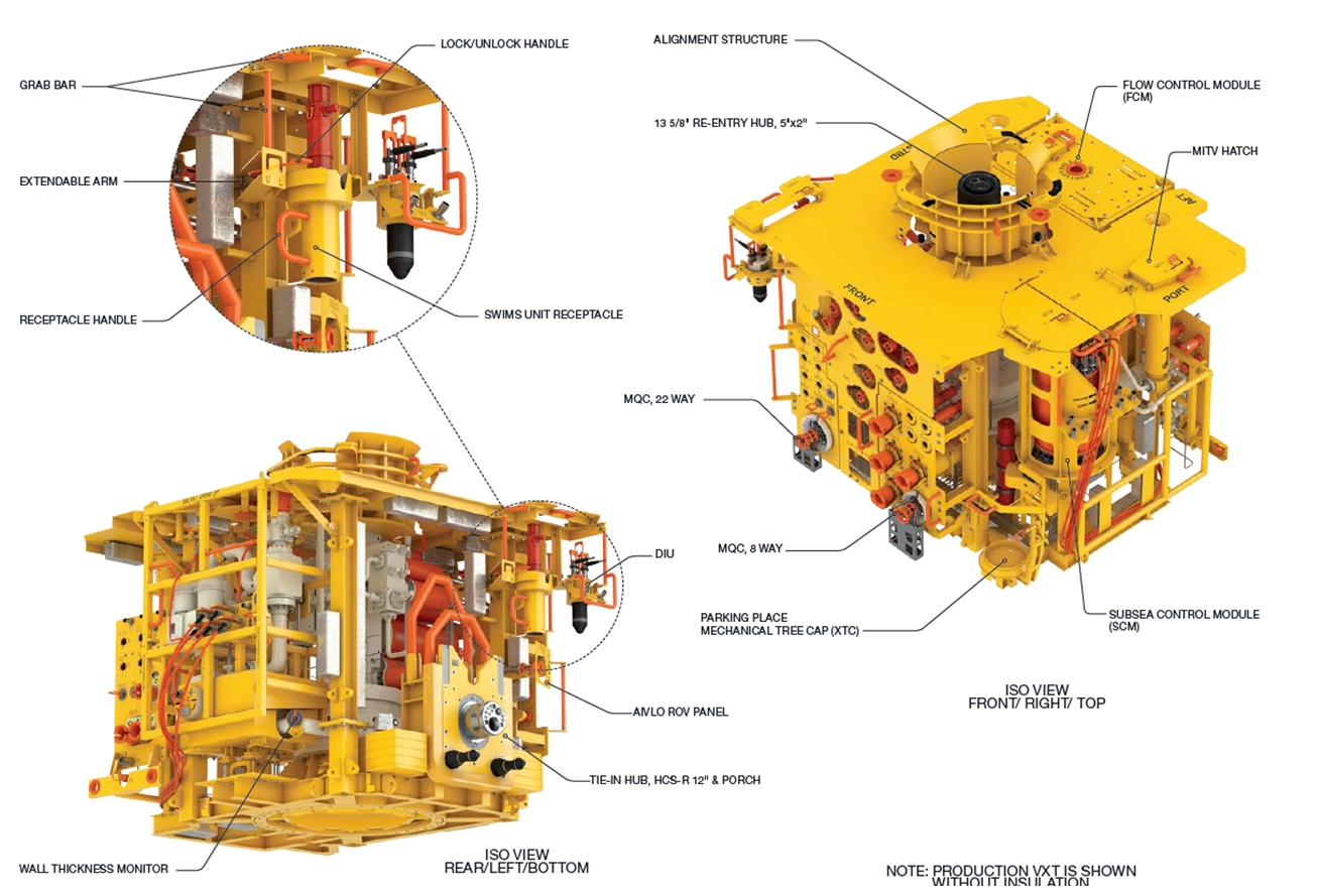
2.2 Subsea Production System
A subsea structure has to be designed and equipped with due consideration of the following additional mechanical aspects:
Space provision for the selected connector dimensions, tie-in tools and ROV operating envelope.
Tie-in aid equipment such as guiding devices, supporting devices, latching systems, etc.
Equipped with an inboard hub compatible with the future flow-line connector,
Connection/reaction load capabilities, which vary with the selected tie-in method and nature of equipment connect (rigid or flexible jumper/spool),
Design to resist in-service conditions such as temperature, pressure, slugging, corrosion, erosion, etc.
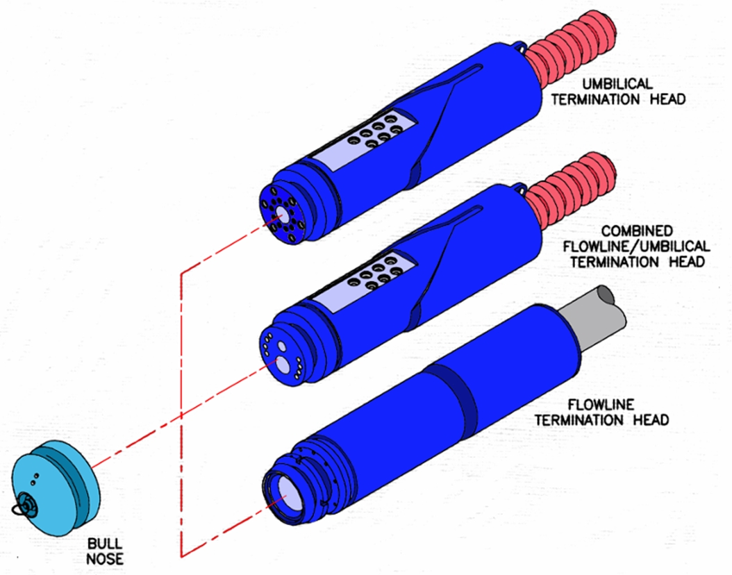
2.3 Flowline and Umbilical Terminations
The flow-line termination must be designed and equipped with the following considerations:
Tie-in outboard hub compatible with the future connector.
Pulling devices, guiding structures, tool jig, etc., may be included in the termination head or PLEM.
2.4 Vessels
One or several vessel/ships of the following types could be involved in a tie-in operation:
Laying vessel
Drilling/completion rig
The vessel and tie-in method choices are intimately related. Some tie-in methods would require the presence of two vessels (e.g. the Lay-away tie-in method, see "5.6. Surface tie-in, lay-away and lay-to", which requires the simultaneous presence of the laying ship and the drilling rig), this interface can have a costly repercussion on the project.
Launching and recovery of both the ROVs and the ROTs can also be defined as an interface item as its performance have a direct impact on the time (hence the cost) of a tie-in operation.
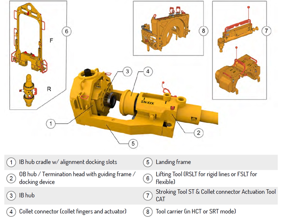
2.5 Connection Tools
A set of tools exist per connector type to perform several functions (connection/disconnection, hubs cleaning, seal change out, acid injection, torqueing, etc.).
The connection tools set design is based on:
Connector types, e.g. mandrel, collet, clamp
Tie-in methods, e.g. vertical or horizontal spool
Remote intervention methods, e.g. ROV intensive or ROT with ROV used for back-up function only.
Type of equipment on the outboard side of the connection (flowline, rigid jumper/spools, flexible jumper/spool, umbilical).
The connection tool design depends on the connector type (which determines the required functions: hydraulic supply, torque tool, integrated seal plate handling and replacement tool, etc.) and varies with each manufacturers. Some tools are proprietary (developed by SPS manufacturers or other manufacturers) and some are more common on the market (torque tool, hot stab, etc.).
The connector and connector selection is made and/or validated by the Project team.
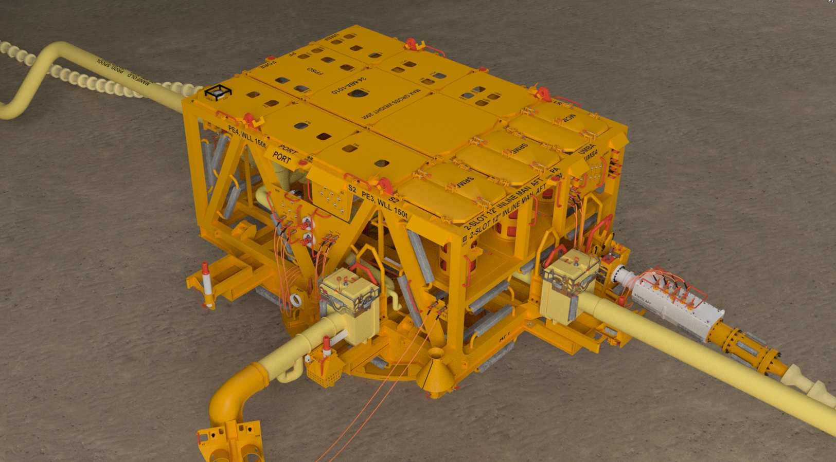
Today tie-in techniques are mainly based on ROV light tie-in tools deployed on the seabed via a dedicated deployment basket.
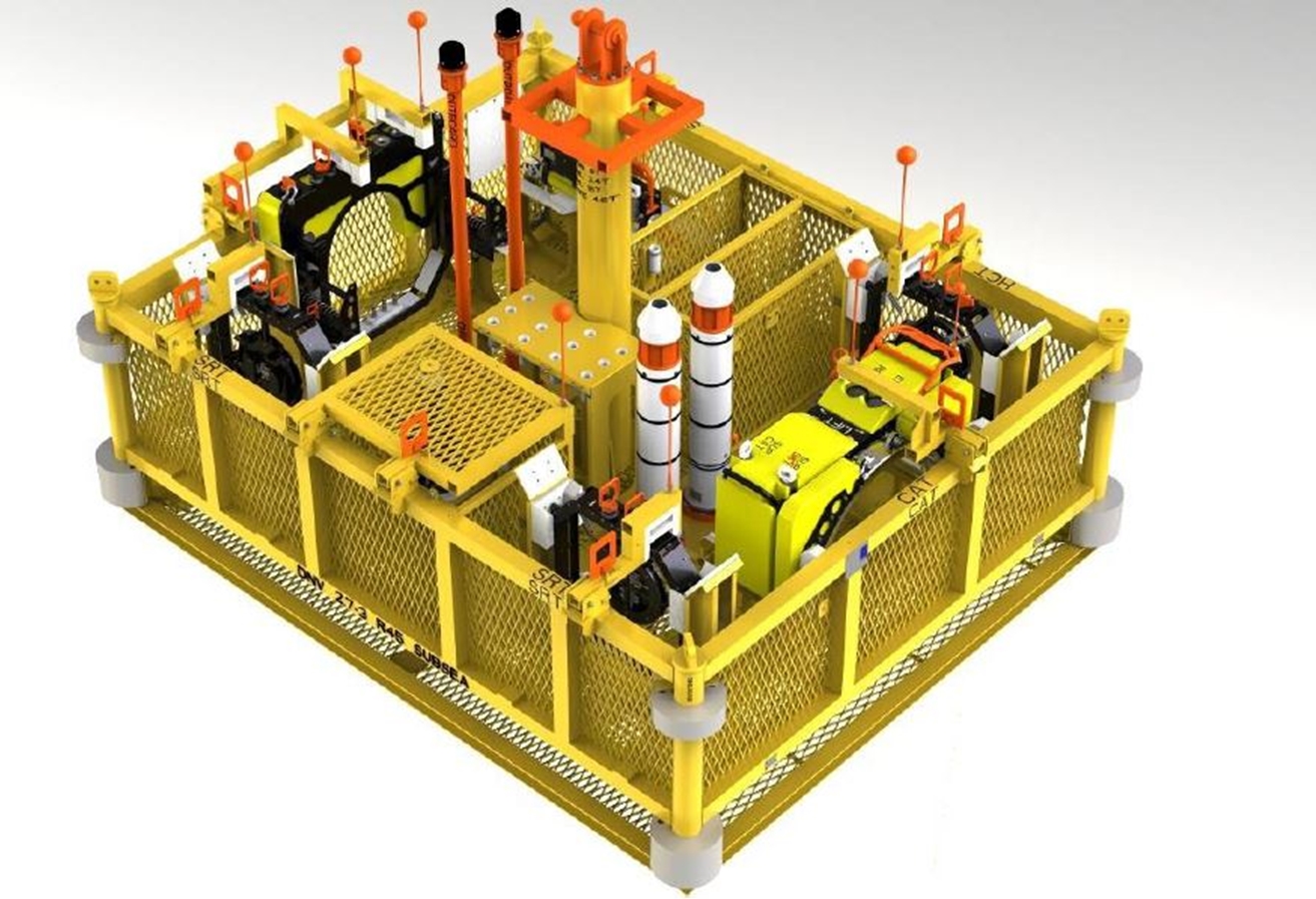
A subsea intervention around a connection can be considered heavy; it involves the mobilisation and preparation on deck of a set of tools + set of contingency tools (in case something goes wrong). Instead of lifting one by one all tools on seabed, a dedicated tooling basket is utilised, as shown on picture above.
2.6 Remotely Operated Vehicles
For the ROT/tie-in method, the ROV is used primarily as a visual control during the ROT landing and recovery, and to connect the pull-in wire (see chapter Section 5.3, “Flexible Spools, Jumpers, Spur Lines” "Lay-down and pull-in"). Its secondary function is to override some of the ROT main functions in case of an ROT mechanical failure.
In this case the main interfaces are related to:
With regard to the ROV mounted pull-in and connection tool, the interface requirements are much more stringent and could referred to "Interface Engineering" encompassing the full scheme, such as the designs of:
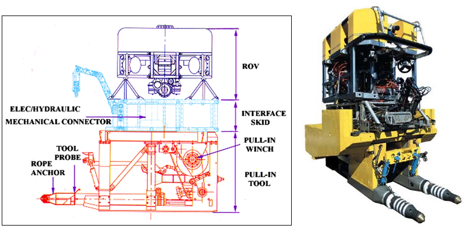
For modern tie-in systems, the tooling must be as light as possible, easy to manipulate, robust and ROV friendly (see UCON-H ROV tooling shown below).
However the tooling could become heavier and more complex when connector sizes increase (42in tooling on Ichthys).


