
3 Connector Technology and Manufacturers Review
3.1 General
Deepwater tie-ins imply the use of diverless subsea connectors that allows connecting two hubs (one inboard and one outboard hub) which are separately welded to the line extremity sections.
Their implementation requires precise alignment. This is generally performed in two stages:
Rough alignment during the hub's approach by the pull-in tool or by means of guiding funnel placed on the subsea structure
Precise alignment, tapered entrance profile on the two hub faces provides the final precise hub alignment in preparation for connector make up.
In the case of a multibore connection, the seal plate geometry is adapted to mate the two hubs and is equipped with guiding pins in order to perform precise alignment and rotational orientation.
This section aims to describe the connector technologies currently available for subsea tie-in operation and to identify the main manufacturers.
The tie-in technology proposed on the market today is of several types:
Collet connector
Clamp connector
Mandrel connector
The whole objective of a tie-in technology is to ensure sealing over time and under operating/environmental conditions. Each technology proposed by a vendor contains its own benefits and disadvantages with regards to hubs engagement and sealing technology.
These systems allow both monobore and multibore connections as only hubs and seal plates have to be adapted.
The running tool can be either remote or integrated into the tie-in.
For remote tie-in it could be a large Remotely Operated Tool (ROT) or a large ROV-mounted tool or some small light weight ROV friendly tools.
For production system, an insulation system can be placed at the later stage onto the connection point as required, using for example a doghouse (insulated box with an open bottom and horseshoe cut-out front and back to allow its landing on the connection prior to its closing) or a dedicated halves clamp of e.g. syntactic foam.
Last generations of connectors have integrated insulation (insulated UCON-H from TechnipFMC or HCS/VCS from Aker Solutions).
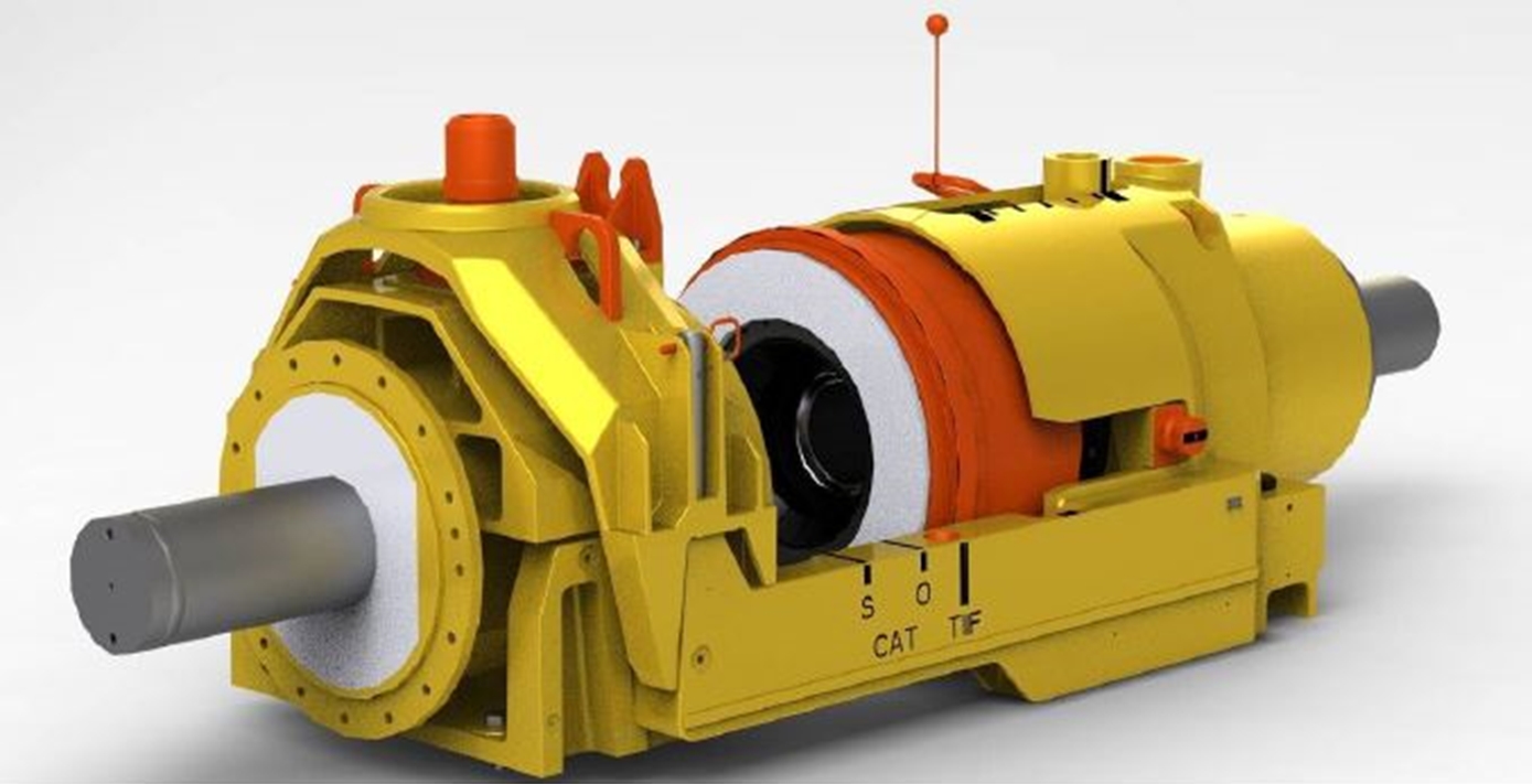
Figure 3.2 - UCON-H insulated (insulation in white) Termination Head docked onto inboard cradle (TechnipFMC)
The above mechanical connectors are widely used in deepwater field development.
Other mechanical connectors are available, however with lower utilisation in deepwater application:
3.2 Collet Connector
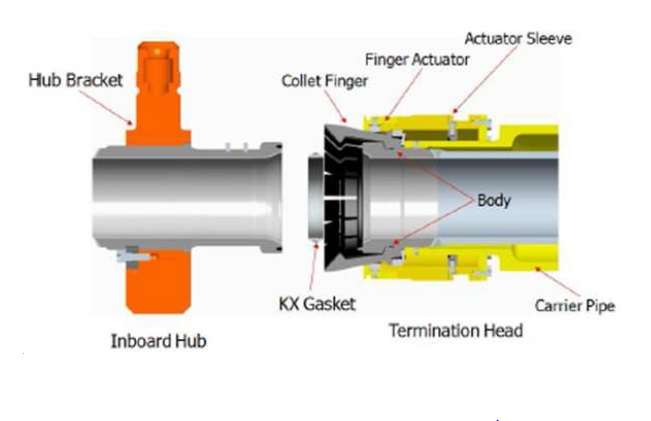
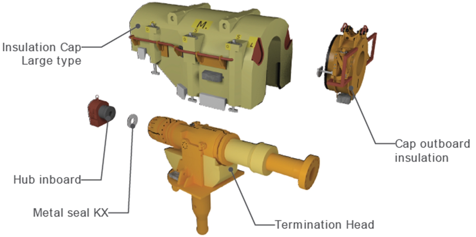
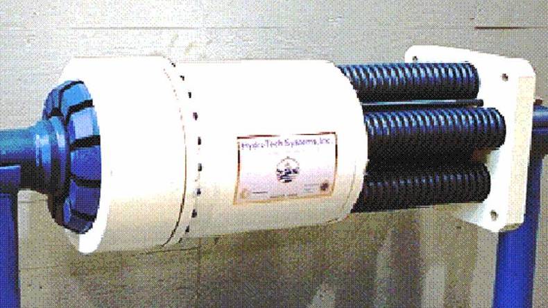
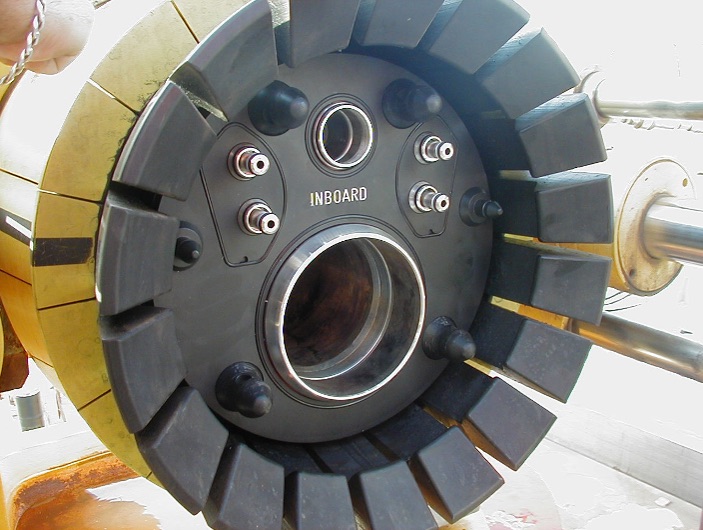
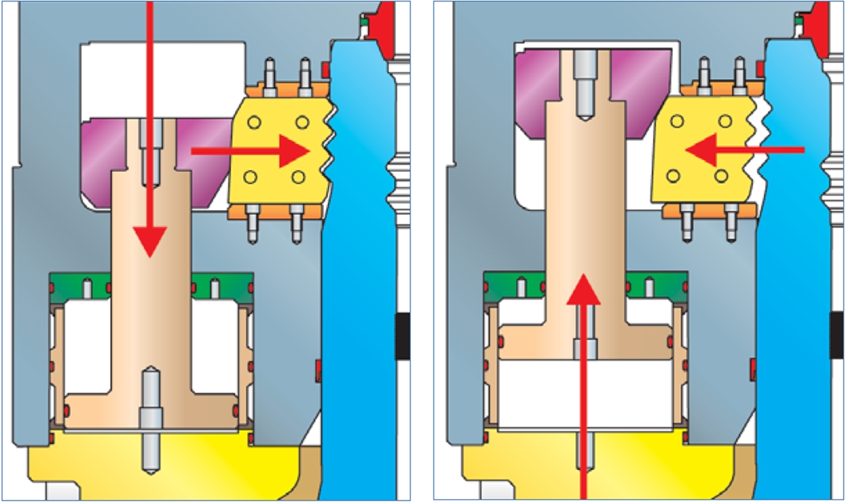
A collet connector basically consists of two mating hubs: an inboard hub and outboard hub (also called termination head) which supports the collet fingers, the finger actuator and the actuator sleeve. The metal seal may be retained in either the inboard hub or the outboard hub, maintained in position by mechanical adjustment or retaining O-ring (compressed when seal in position inside hub).
The functions of each component and operations of the collet connector may be described as follows:
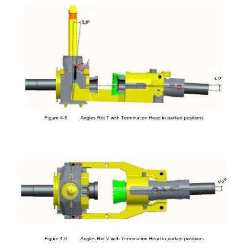
The first step of a connection operation is the stabbing: the two hubs are brought into approximate contact (by a stroking tool). Few degrees misalignment, depending on the diameter of the line, can be corrected by the collets (e.g. +/-2° angular misalignment and +/-35mm axial offset satisfy most applications).
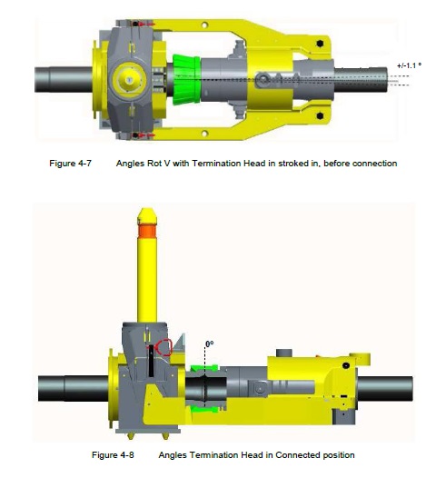
Locking is then performed by the collets. This is done by applying hydraulic pressure to the cylinders, which transmit a force in the axial direction to the actuator ring; the actuator ring then moves axially and forces the collets radially inward.
The collet connector is maintained closed by the locking springs; this preload keeps the two hubs and the metal seal in tight contact and determines the bending strength of the connector. The metal seal integrity can be externally tested.
Note that recent collet connectors design used springless locking system. For TechnipFMC collet connector the driving angle on the actuator ring/sleeve is defined to allow self-locking of the locking fingers and there is a secondary locking (mechanical) system that locks any translation of the actuator ring/sleeve.
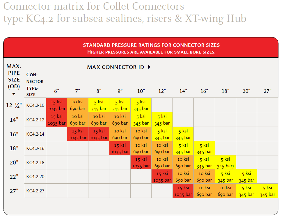
Typical size and pressure rating values of collet connectors range from 3" to 36” API. Here below are shown pressure rating depending on max pipe OD and connector size.
The collet connector is probably the most cost-effective connector and has been extensively used in the Gulf of Mexico and West Africa deepwater developments; it is manufactured by:
Oil States
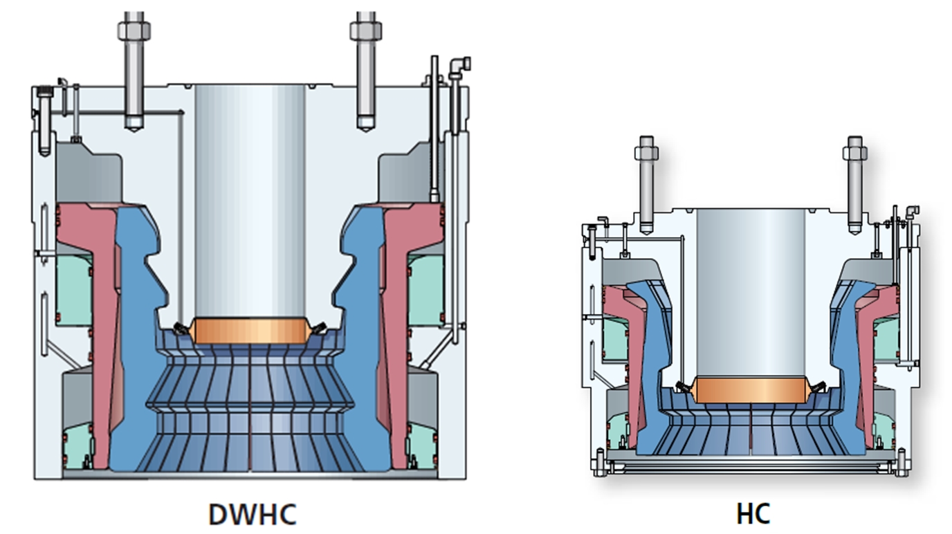
Schlumberger (HCH4, HC, DWHC)
TechnipFMC (KC)
Dril-Quip (DQ-VC)
General Electric (6” VH, MCV)
Typical load capacity for Collet Connectors rated for 5000psi is detailed in the following figure:
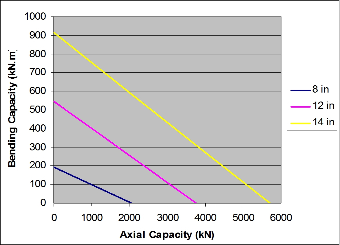
Bending moment capacity @ 0 pressure and 0 tension for:
18 ¾” DWHC connector: 11 500 kN.m
18 ¾” 15 000 psi API flange type 6BX: 8 000 kN.m (leakage controlled) for a bolt make-up of 52.5 ksi
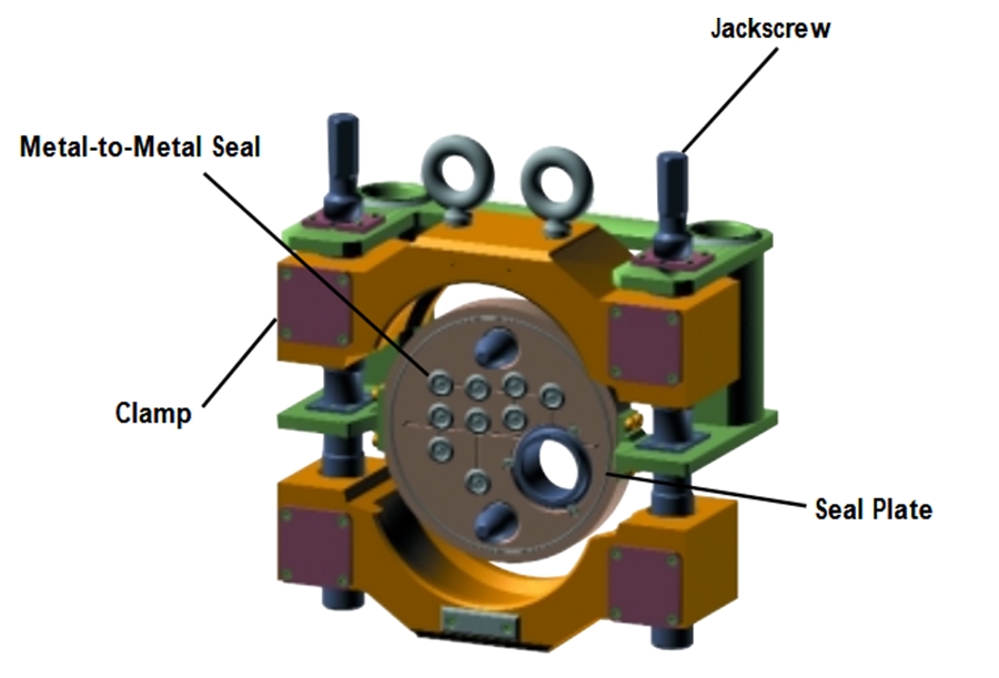
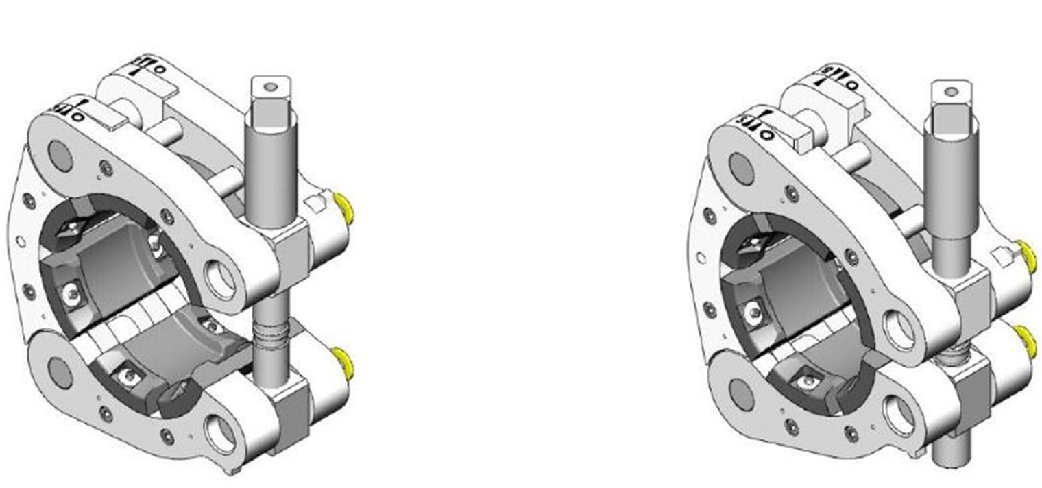
3.3 Clamp Connector
The inboard and outboard hub principle is exactly the same between the collet and clamp connector, the difference is on the way to apply a pressure of one hub against the other one.
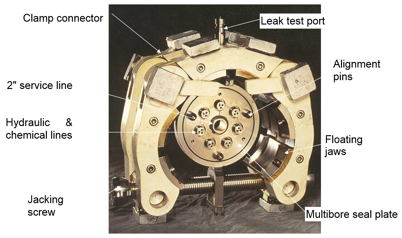
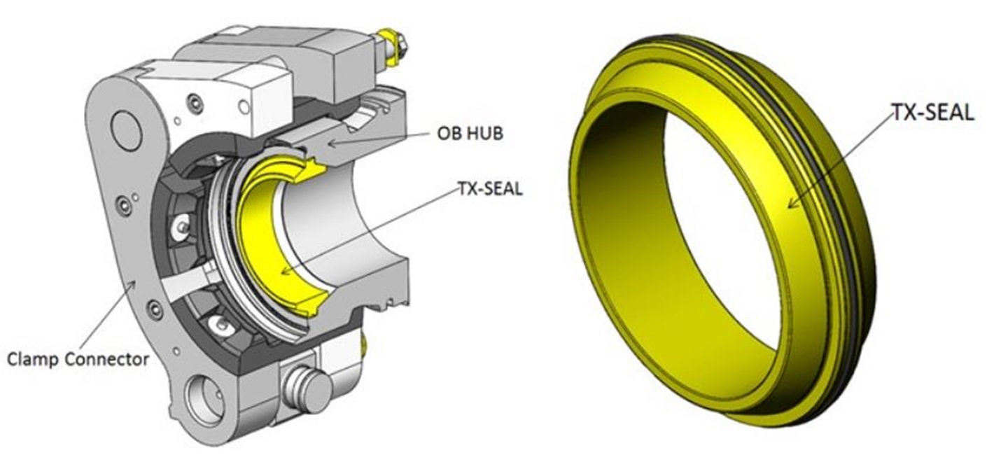
This system consists of a clamp assembly (2 segments or 3 segments hinged clamp), a seal plate and two mating hubs. The clamp assembly may be a two jacking screw type (and consists of upper and lower clamp halves) or a single jacking screw type (see above Figure 3.10, “Multibore Clamp Connector (clamp and seal plate), by courtesy of Aker Solutions”) connector with a monobore seal or multibore seal plate, fitted with guiding pins for precise alignment and orientation, and the leak test port, passing through the clamp, which also plays the role of seal plate retainer in this case.
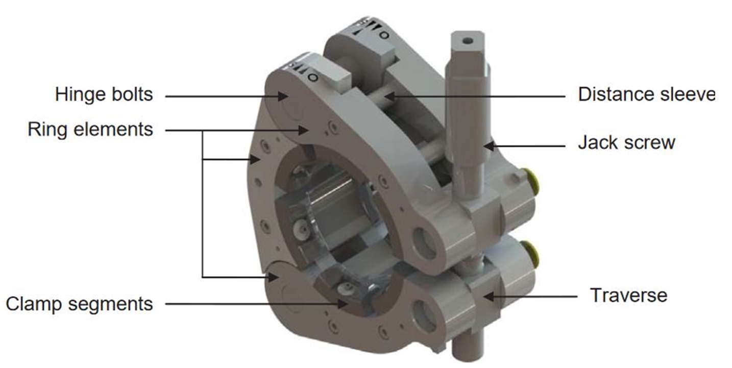

Figure 3.12, “Single bolt clamp connector arrangement (courtesy of Destec)” depicts the clamp connector principle: rotating the jack screw allows opening or closing of the clamp segments, which in return apply/release pressure on the 2 hubs against each other.
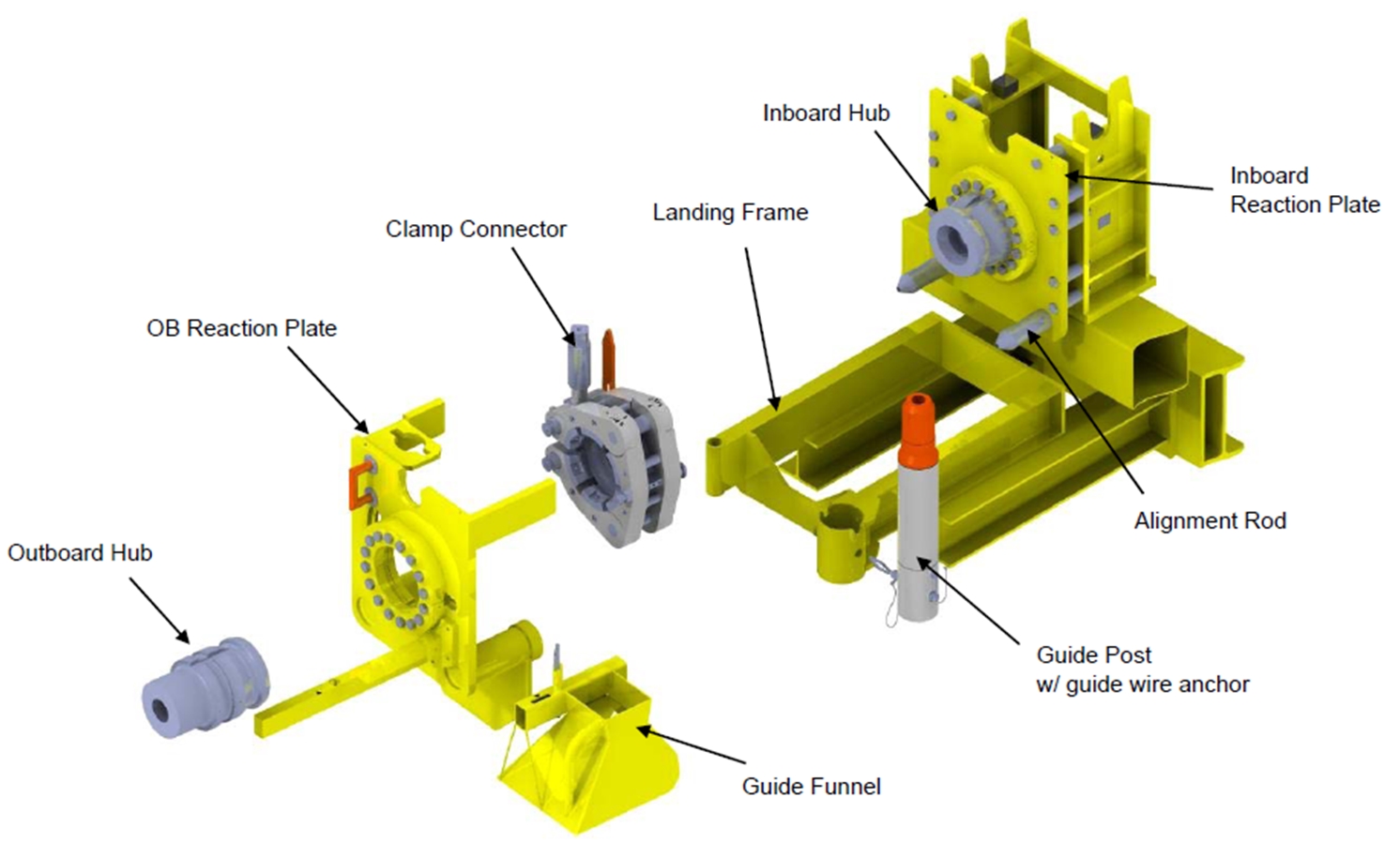
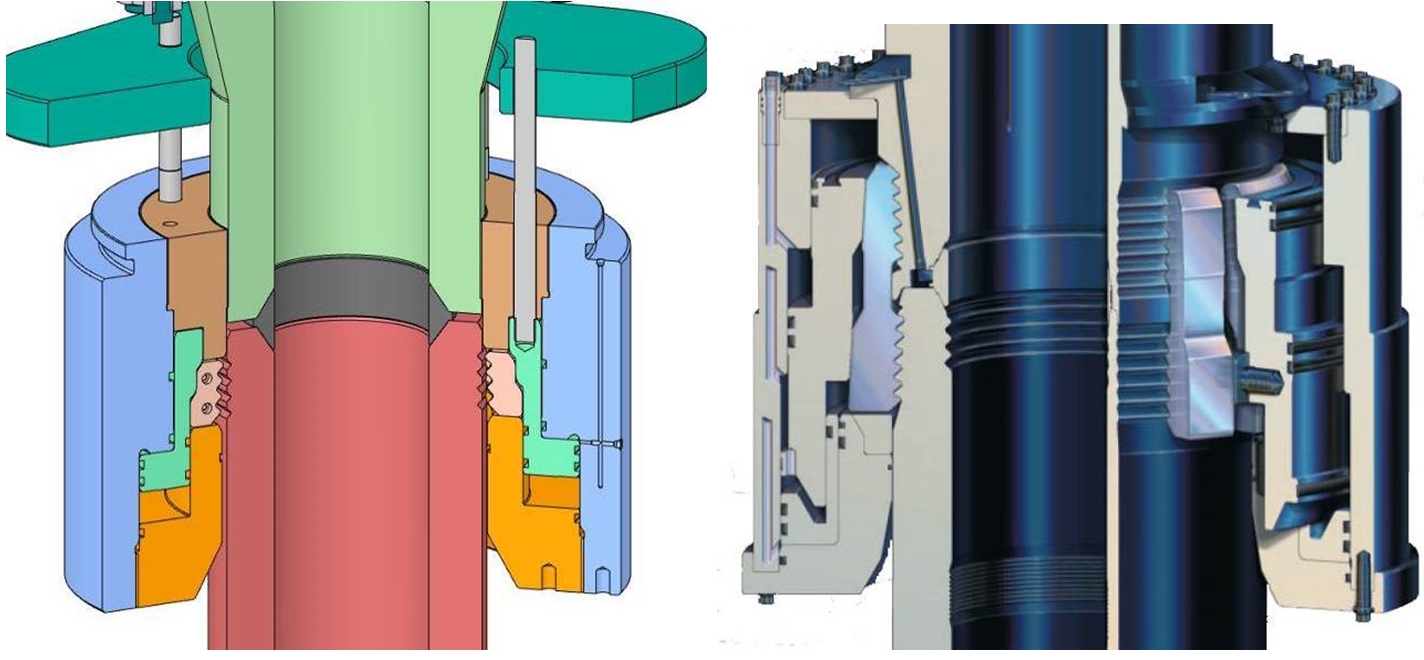
Performing a connection with a clamp connector mainly consists in:
Mating the hubs and the seal plate with a stroking system. If the connection is made-up with an ROV-mounted tool system, the clamp assembly is deployed with the subsea module and the seal plate is inserted by ROV tool; if the connection is made-up by an ROT, both clamp and seal plate are deployed together with the connection tool.
Closing the clamp by tightening the screw(s) with a torque tool. Torque force and number of turns are carefully monitored. Torque will vary during tightening operation (breakout torque, running torque, make-up torque, max allowable torque).
Performing the back seal test. A hot stab receptacle provides a pressure test line into the seal annulus.
The clamp connector with the collect connector are the main connectors used in all major deepwater oil regions (i.e. North Sea, Brazil, Gulf of Mexico, West Africa, etc.) due to its robust construction and reliability.
Clamp connector can be provided for almost any diameter in accordance with the API 5L specifications and up to 10 000 / 15 000 psi (as required).
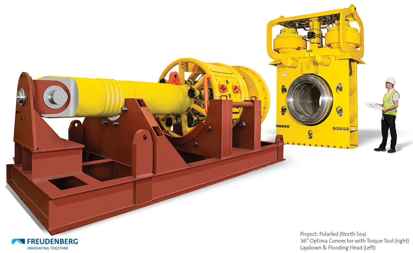
Note that Destec clamp connector size range is from 2” until 60” with pressure rating up to 15 000 psi.
The main manufacturers are:
BHGE (Graylock design)
Schlumberger (McPAC clamp and seal plate systems)
Aker Solutions
TechnipFMC
Destec
AF Global
Freudenberg
EAB Engineering
Oceaneering
Oil States
Trendsetter
Kongsberg
Etc.
Typical load capacity for clamp connectors rated for 5000psi is detailed in the following figure:

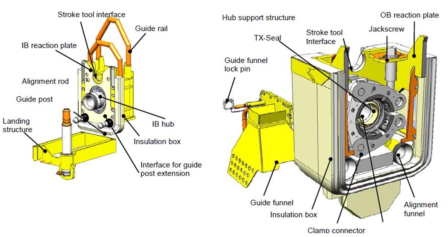
In the pictures below is shown AKER HCS tie-in system.
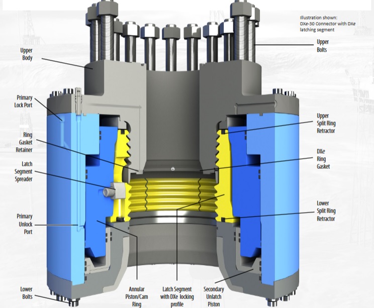
3.4 Mandrel Connector
The mandrel connector has been originally developed for drilling operations and well connections. This connector is also used in ultra-deepwater riser attachments (in Brazil) when extra-strengths are needed, e.g. high tensions combined with bending and torsion.
Various configurations of mandrel connectors exist, which are based on the principle of driving a split ring or dogs into a groove using an activation sleeve in a similar manner to the collet connector.
A mandrel connector functions in a similar way than a collet connector, it is mainly the profile of the locking segments which is different between the two connection systems.
Main applications of mandrel connectors are the following:
Compared to collet or clamp, mandrel connector is mainly used for applications that require high load, torsion and bending capacity.
Schlumberger DWHC connector is a collet connector used for drilling equipment (typically used for connection of the BOP stack to the wellhead or to secure the lower riser package (LRP) assembly to the top of the BOP) designed for high loads and moments encountered in ultra-deepwater applications. The capacity of this connector is given as exceeding the capacity of a standard API flange.
The main manufacturers are:
GE (H3 or H4)
TechnipFMC (Torus connector)
Dril-Quip (DXe)
WOM (18 ¾-10K Riser adaptor Connector)
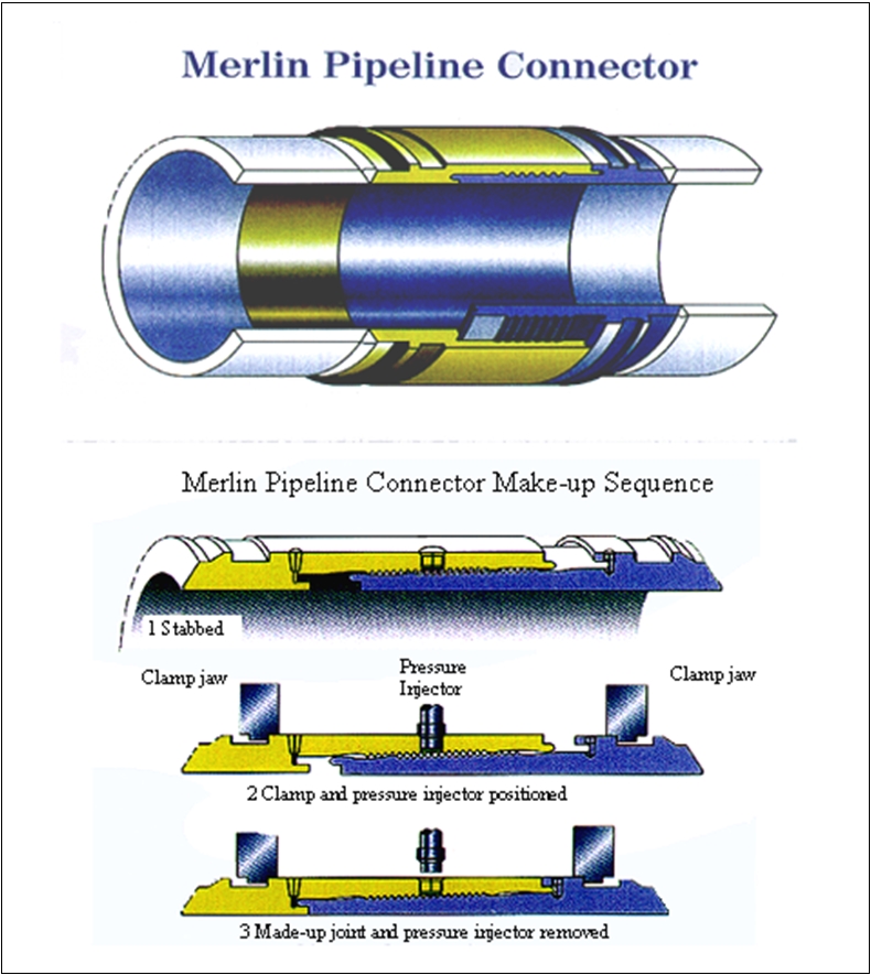
3.5 Merlin Connector
The Merlin connector is composed of two (inward and outward) hubs, both notched on the mating face. The connection operation consists in:
Stabbing of inward hub onto outward hub
Injecting pressured fluid within the two mating hubs while pushing them together with clamp jaws
Release pressure when inward and outward hubs are fully engaged
The Merlin connector is available from 8" to 36". It has been used by Subsea 7 on the BP Harding field to fabricate a rigid pipeline: the pipe strings were laid on the seabed and then assembled by means of Merlin connector.
3.6 Conventional and Compact Flanges
Flanges are generally not used in deepwater subsea tie-ins. Flanges are mainly used for assembling subsea components in workshop or ‘at surface’ prior to its subsea deployment. When connection is made subsea, it implies the intervention of divers, which limits the water depth of the subsea connection. The exception being the use of flanges implemented by means of a purpose-built diverless tool like MATIS tool used on the Girassol field (see Section 3.7, “Flanges used for diverless connection”).
The principle of a standard flange (e.g. API, ANSI) is to use the mechanical force exerted by the bolts to pre-load the steel gasket sufficiently so that when internal pressure is applied, there is enough contact stress between the flanges and gasket to maintain a seal. This design hence features a load path through the steel gasket, with no firm contact between the flange faces. The whole connector consists of two flanges, a seal ring and a set of stud bolts.
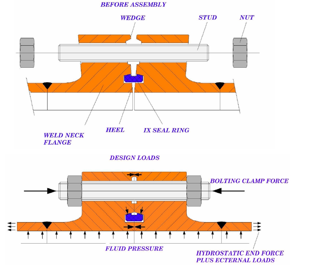
Another design allows a more Compact Flange design. The principal features of the compact flange are (1) the flange face geometry and (2) provision of a double metal seal.
The compact flange face includes a slightly convex bevel with the highest point, called the heel, adjacent to the bore and a small outer wedge around the outer diameter of the flange (see ). The compact flange connection is made up by tightening/tensioning the bolting which pulls the two connector halves together. Axial forces are exerted on the taper of the metal seal ring and translated into a radial sealing force. The bevel is closed by the bolts tensioning and face to face contact is achieved at the outer wedge while most of the bolt preload is transferred as compressive forces between the flange faces at the heel.
The design of the compact flange features two sealing locations. The first seal is created by application of seal seating stress at the flange heel. Throughout the complete range of normal operating loads a contact stress in excess of the operational pressure is maintained at the heel seal location. The flange also remains in contact along its outer circumference at the flange faces. Finally there is an elastic seal ring which is compressed radially. The seal ring force is provided by the elastic stored energy in the stressed seal ring. Any accidental heel leakage will give internal pressure acting on the ring inside intensifying the sealing action.
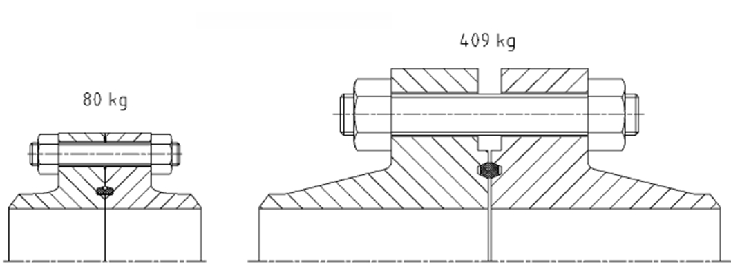
The Compact Flanges provide an alternative to conventional flanges with reduced weight and smaller overall dimensions.
While a conventional flange features load transfer through gasket, the compact flange conveys the different loads (axial and loads induced by bending moments) through the flange faces, thus increasing the seal reliability. Whereas conventional flange connectors subject to bending tend to separate (this reduction in the face compressive force directly results in a reduction of the gasket seating loads), the compact flange seal ring load does not depend on the resulting compressive force between the two flange faces as long as they remain in contact. Hence, the compact flange is capable of withstanding higher bending loads than a conventional flange before leakage.
The compact flange connector is mainly represented by the SPO compact flange, developed by Vector International AS. The SPO compact flange was first used in the late 80's, e.g. for production risers and export risers. Since then, it has been used for a number of (surface-made connection) applications such as titanium drilling risers and flexible riser end-fittings.
3.7 Flanges used for diverless connection
Flanges that are intended to be make-up subsea are based on API or ANSI flange but required some modifications:
Swivel flange to allow alignment for studs and nuts
A back seal test port is added at the seal area
Pressure holes are drilled through gasket to avoid hydraulic lock during connection make-up.
Main flanges used for diverless connection subsea are:
API 6A (type 6B or 6BX)
ANSI/ASME B16.5
API 17D (type 17SS or type 17SV)
ASME/ANSI flanges are common in industrial process systems like handling water, steam, air and gas. API flanges are manufactured for high strength operating refinery systems with products such as oil and explosive gases.
The flange standards API 6A and ASME/ANSI B16.5 have similar dimensions, main difference is the fabrication material used for API 6A that gives them a higher rated operating pressure.
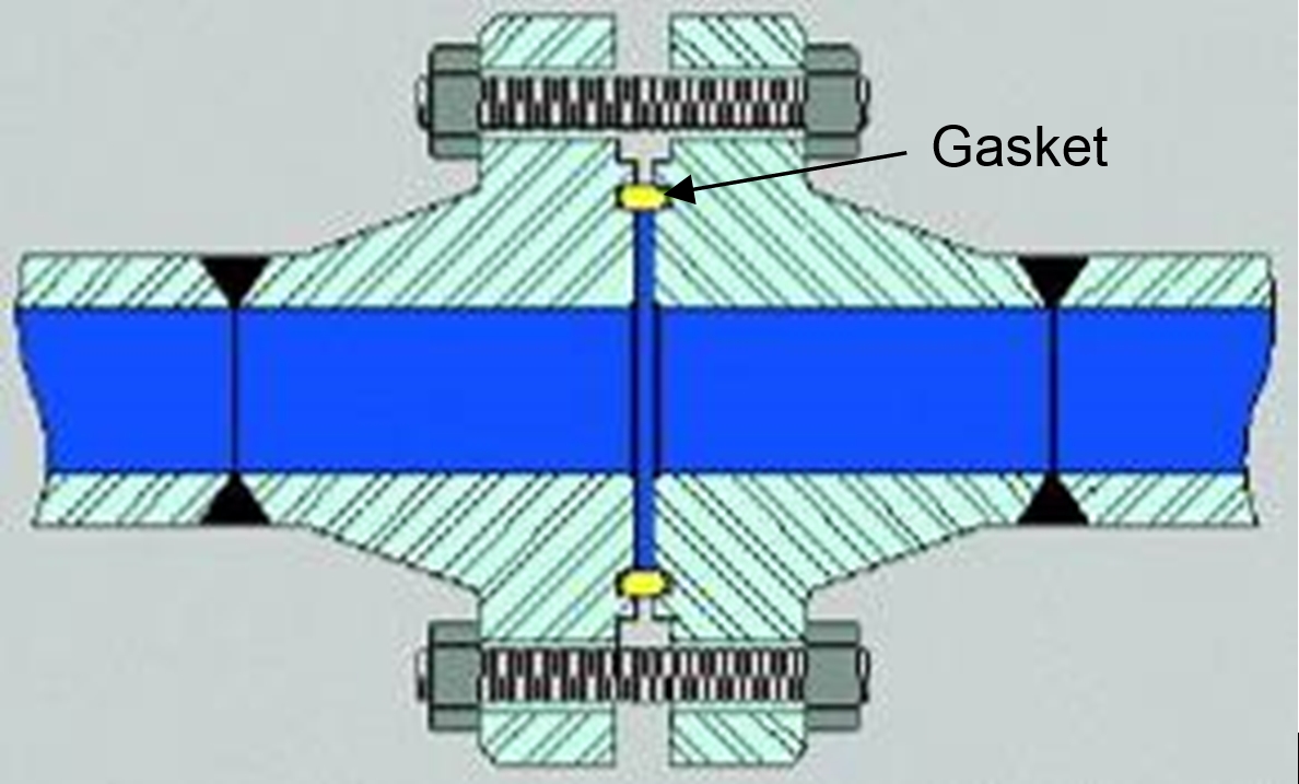
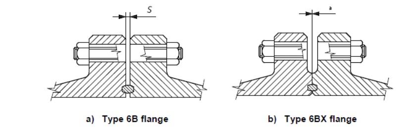
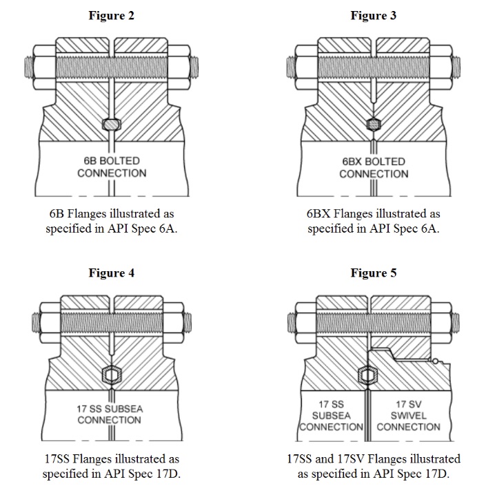
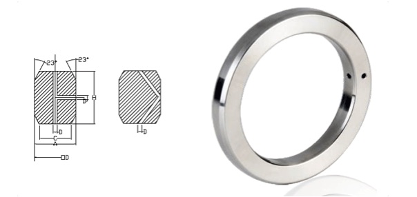
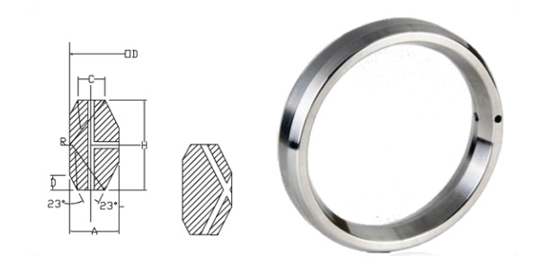
API 6A type 6B and 6BX are Ring Type Joint (RTJ) flanges. Main difference between the two types is that type 6BX has a raised face.
Another significant difference between 6B and 6BX flange is that 6B flanges are not designed for face-to-face make-up. For 6B flange the connection make-up bolting force reacts on the metallic ring gasket (see ).
For 6BX flanges depending on the tolerances, the connection make-up bolting force may react on the raised face of the 6BX flange when the gasket has been properly seated (see ). This support prevents damage to the flange or gasket from excessive bolt torque. Face-to-face contact is not necessary for the proper functioning of the 6BX flange.
Type 17SS flanges are based on type 6B flanges, modified slightly for consistency with established subsea practice. The primary modifications are substitution of BX type ring gaskets (replaced by SBX) for subsea service and slight reductions of through-bore diameters on some flange sizes. In addition, type 17SS flanges shall be designed with raised faces for rigid face-to-face make-up. Type 17SS flanges have been developed for the sizes and rated working pressures given in API SPEC 17D table 5 shown below.
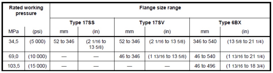
Swivel flanges are often used to facilitate subsea connections that are made up underwater. Type 17SV flanges are swivel-flange designed to mate with standard ISO (API) type 17SS and type 6BX flanges of the same size and pressure rating. Type 17SV flanges have been developed for the sizes and rated working pressures given in API SPEC 17D table 5 shown below.
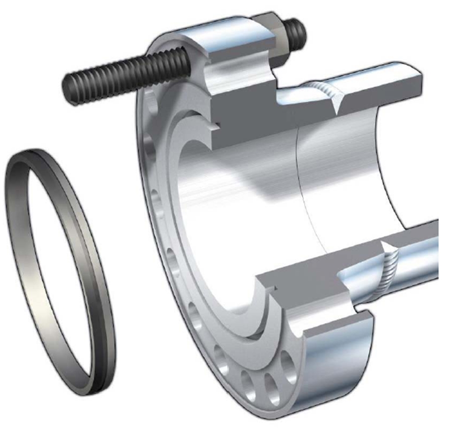
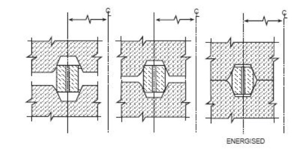
For subsea application, most of the time the sealing solution is a Metal to Metal (MtM) sealing as the gasket is made in metal and will be compressed against the flange groove that is also in metal (gasket is made in a metal softer than flange metal to avoid damaging flange groove surface). The gasket is made slightly larger in diameter than the grooves to allow radial compression of the gasket and good contact with the groove.
Main ring joint gaskets used for API 6A type 6B and 6BX Ring Type Joint (RTJ) flanges are shown on the pictures below.
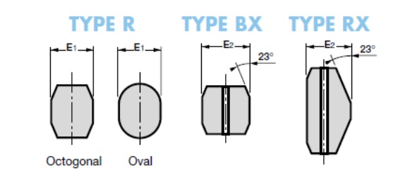
It shall be noted that R, RX and BX gaskets are only used when flanges are made up topside.
RX and BX gaskets incorporate a pressure balance hole to equalize pressure both sides of the sealing faces.
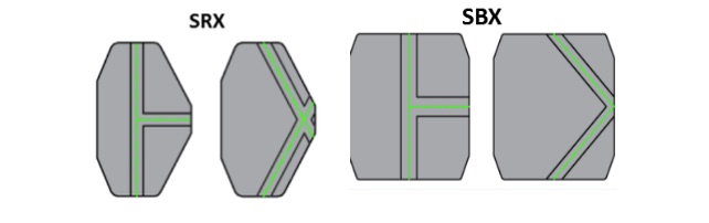
It shall be noted that only SRX and SBX ring joint gaskets can be used when flanges make up is performed subsea. In easy way to remind this is that the first letter is S like for Subsea make-up. Main difference between RX and BX gaskets design is that an additional hole is drilled to allow the escape of any fluids trapped between the gasket and the groove during subsea connection make-up. This arrangement is to avoid pressure lock and improper sealing.
API Spec 17D state that SBX ring gaskets shall be used to seal all API 17D SS and 17D SV flanges and all API 6A type 6BX flanges used for subsea completion equipment.
For more information about ring joint gasket, see:
http://www.woodcousa.com/catalogs/connector-acc15.htm
http://www.oildrillingprocess.com/
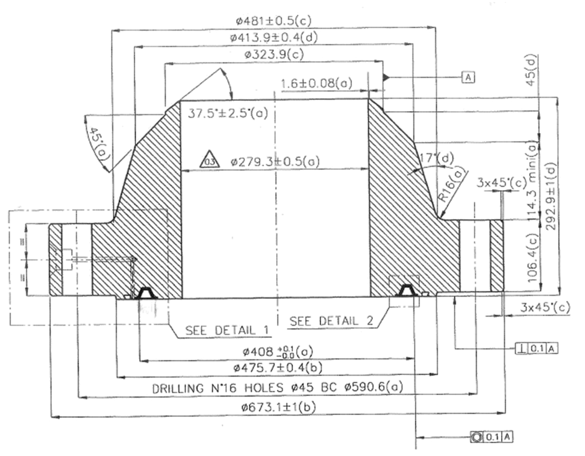
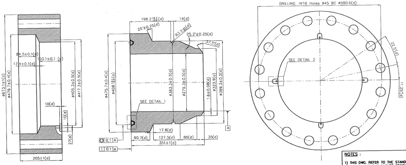
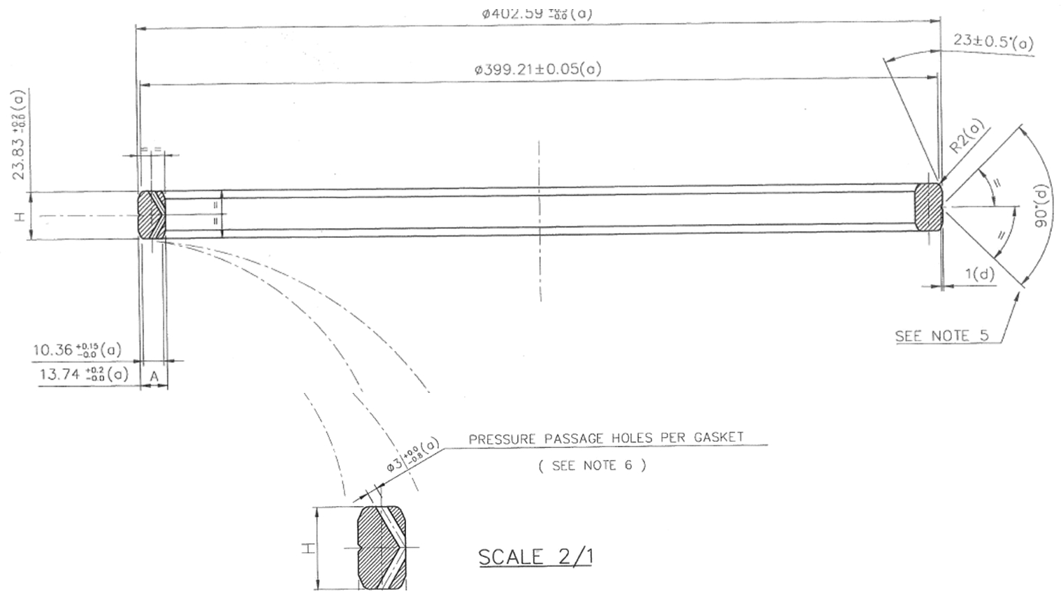
Here after are shown cross section views of Girassol 13" 5/8 API 5000 bolted flanged connection system.
3.8 Electrical Connector
Refer to section 17.5 of Subsea Control Systems Deepwater reference book [104].
3.9 Optical connector
Refer to section 17.7 of Subsea Control Systems Deepwater reference book [104].
Refer to section 17.2, 17.3 and 17.6 of Subsea Control Systems Deepwater reference book [104].


