
8 Subsea Metrology
8.1 General
Some subsea tie-in operations require accurate subsea measurements, especially steel jumper installation because it is necessary to precisely determine distance and angles between the two tie-in points prior to the final jumper fabrication. The "Acoustic Base Line" and "Taut Wire Metrology" described hereafter can be used as the primary measurement means.
A premise for this method is that the subsea structures must be installed within the following tolerances:
Target square box within +/- 5m of its nominal position
Heading of structure within +/- 2.5°
Maximum inclination relative to horizon within 2° in any direction.
8.2 Acoustic Base Line
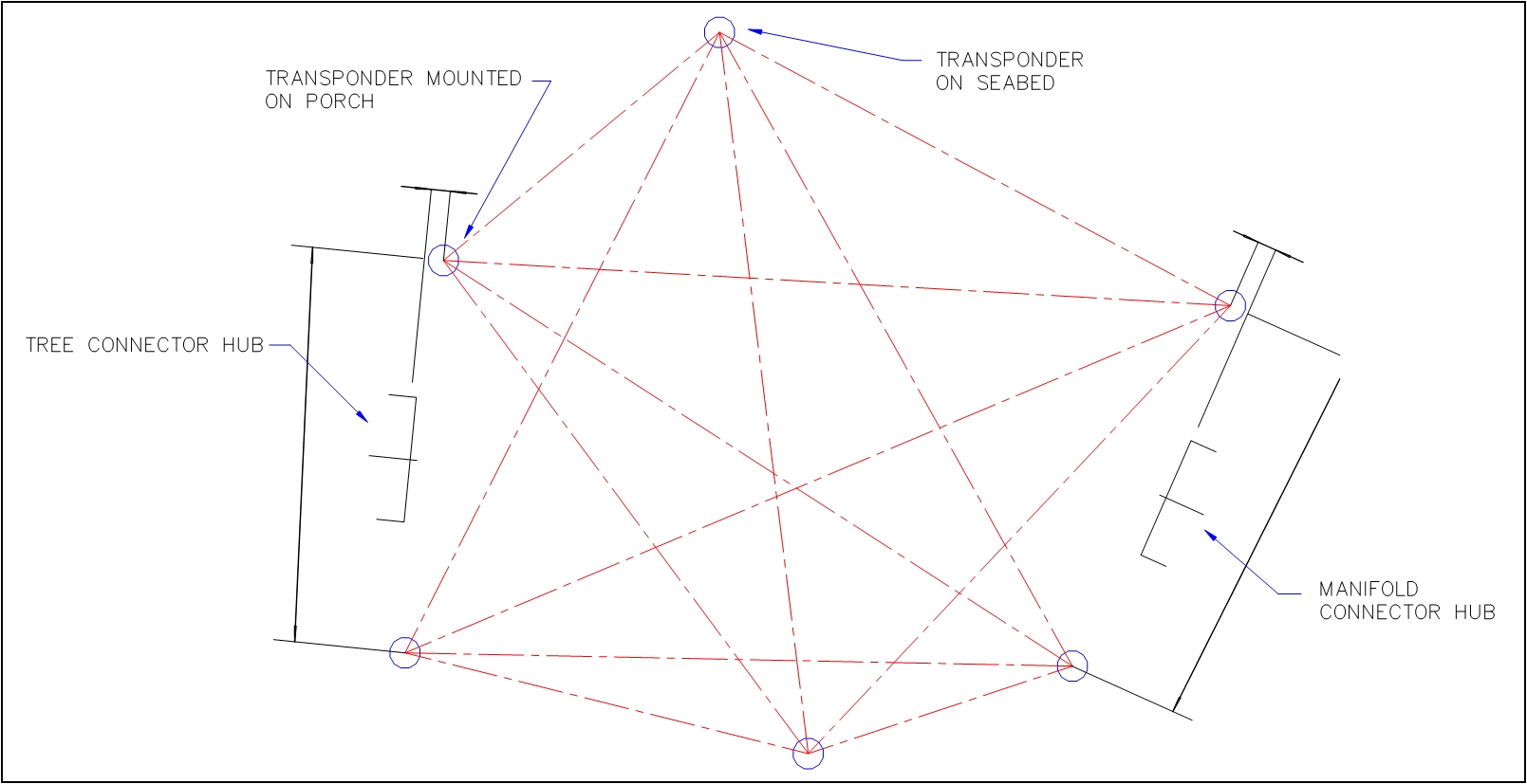
A long base line (LBL) acoustic array is deployed on the seabed by ROV in the area of the jumper route. This array typically consists of up to six extreme high frequency (EHF) transponders: two are deployed on the seabed and two are placed at each tie-in point (a dual transponder arrangement at each tie-in point offers a better level of redundancy).
The array is calibrated after the determination of the sound velocity in water from temperature / salinity measurements. Once the transponders are in position, the programmable acoustic navigator interrogates transponders to measure all baselines. A least squares analysis allows determining the relative positions, orientations and distance of tie-in points. The relative height difference is determined using the pressure sensors in the transponders. To determine accurately the relative orientation between the tie-in points, the ROV can dock on the two points and measure the heading using a precision gyro (i.e. laser based gyro).
This technique typically allows measuring better than +/- 5cm (over a 50m length) and 1° on relative headings.
A typical metrology operation would be between 12 – 24 hours to include transponder deployment and recovery.
8.3 Taut wire metrology
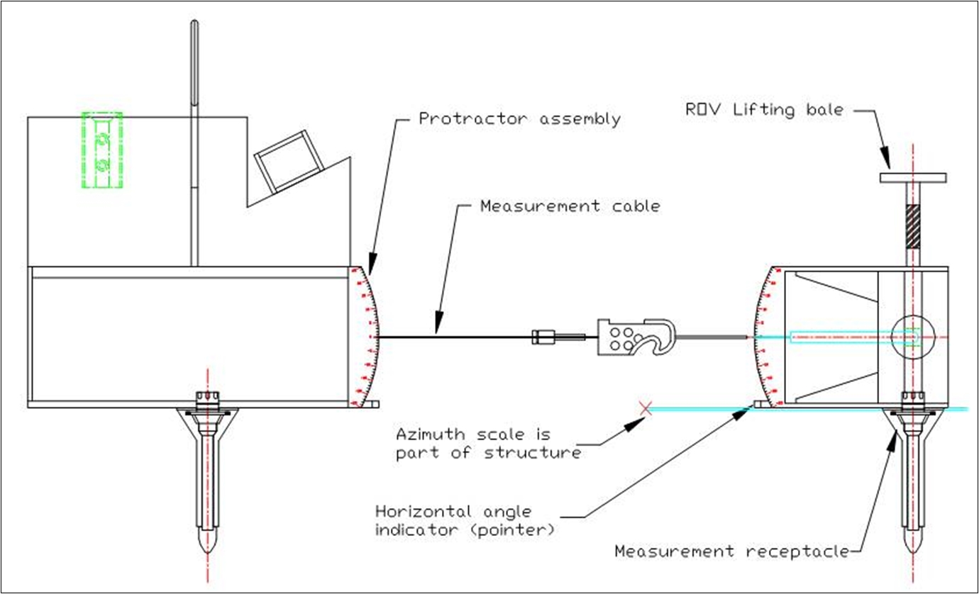
A taut wire measurement tool typically consists of a taut line, winch and protractors with dual axis inclinometers. It is deployed and operated by ROV and a measurement operation consists in:
Installing the tool into the adapted receptacles.
Deploying the measurement cable by ROV and applying tension in the cable with the winch.
Measuring the vertical elevation difference and angular misalignment between the two tie-in points by the protractor and dual axis inclinometer readings. A resolution of 1° can be achieved.
Determining the distance between the two points from the length of the taut line. This length can be measured from a calibrated measuring wheel mounted near the winch. This counter can achieve an accuracy of +/-3cm (over a 50m length).
The ROV video is used to document relative angles and distances between the two points. The measurements are normally repeated to verify values and to help to assess accuracy.
8.4 Photogrammetry metrology
Photogrammetric metrology is a highly specialised application for subsea metrology applications. The basis of photogrammetry is to build a 3D model based on a sequence of 2D photographs. Measuring bars placed on the seabed and reflective markers on the structures provide scaling and reference.
Cameras are deployed on an ROV and sequences of photographs taken along the intended jumper/spool route. The images are processed using software to derive a 3D model of the positions of the hubs, the seabed and other points of interest on the subsea structures.
The advantages of this system are the potential high accuracy of the results, and the fact that in a single survey a very high quantity of information can be gathered. The disadvantages are that image processing makes very intensive demands on computer time; good subsea visibility is required, and also specialist personnel and equipment.
8.5 NS Metrology
Availability of inertial navigation systems has greatly increased in recent years. Inertial navigation systems (INS) use three accelerometers and three gyros to compute a position based on a known start point and the measured changes in velocity and attitude. Unaided INS do not need an outside signal or reference to compute a position; because they are self-contained they do not require line of sight and they are not affected by poor subsea visibility or a noisy subsea acoustic environment. The main drawback of INS metrology is that without such external references, it is subject to cumulative error over time, referred to as INS drift. In order to mitigate these cumulative errors and maintain accuracy,
INS technology offshore is most of the time used in hybrid or aided form with other positioning systems. Data input from existing positioning systems is used to augment INS data to provide a more robust and accurate overall positioning solution than would otherwise be possible.
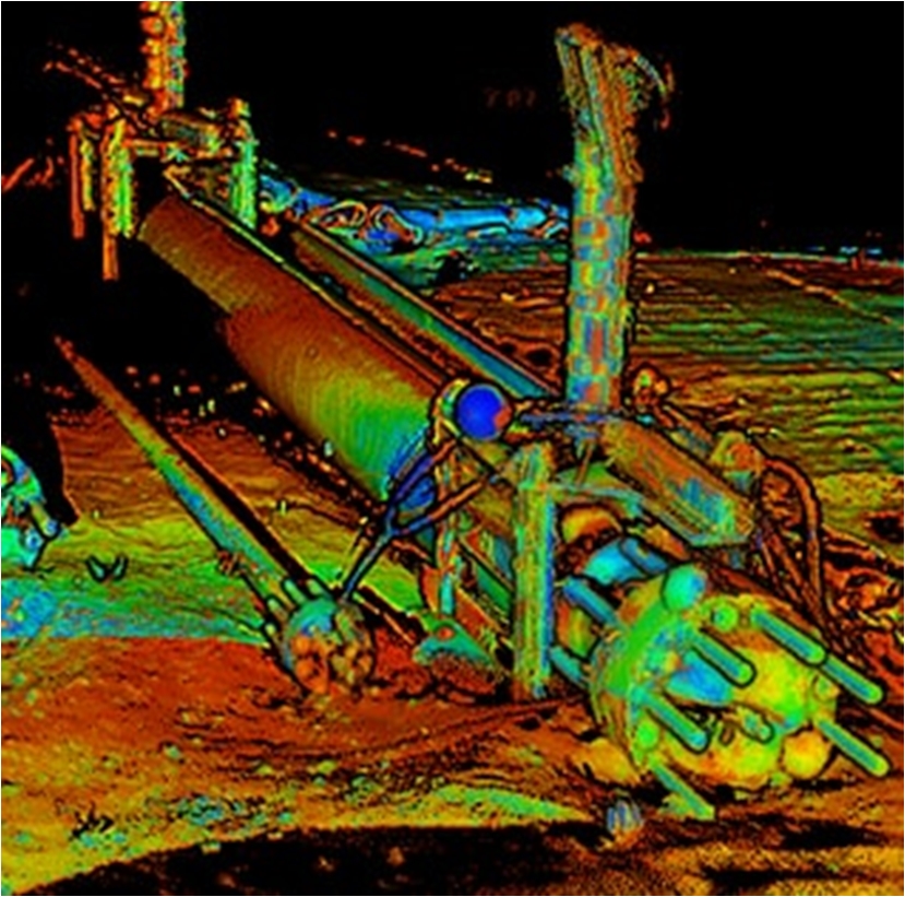
8.6 3D laser scanner
3D laser scanner is a recent technique for subsea jumper/spool metrology.
The 3D laser scanner is fitted to the ROV and is used to create highly detailed, point cloud images of subsea structures where inboard hubs are mounted and the surrounding environments.
8.7 Hybrid technologies
It consists of combining the different techniques described above in order to enhance measurement accuracy and reduce time of acquisition.
For example, by combining the 3D laser data with precise underwater acoustic and inertial navigation information, it is now possible to generate centimetre resolution engineering models from which accurate measurements can be instantaneously and repeatedly captured.
Traditionally the vessel time to acquire the metrology data can take between six and eight hours per metrology. The adoption of a smart combination of proven technology can reduce data acquisition (and hence vessel) time to around two - three hours.
For more information and guidance about different methods for subsea metrology refer to IMCA S 019. Time estimated for deepwater tie-in operation
The time required to perform a deepwater tie-in operation will depend greatly on key topics such as:
The choice of the tie-in method
The number of tie-in operations that can be performed in one installation phase (i.e. learning curve effect consideration)
Experience and training of the ROVs and tie-in personnel
The water depth in terms of launching and recovery time based on an average descent and ascent speed of 800m - 1000m per hour
Albeit the above criteria, the benchmark for deepwater tie-in operation could be defined as follows:
24 hours - 36 hours for a stand-alone or single tie-in operation
Average of 6 hours to 12 hours per tie-in, in case of large number of tie-ins (e.g. more than 10 tie-ins) being performed within an installation campaign.
The above timing is to be considered from spread arrival on site until completion of the tie-in operation, ready for departure to other location and without any major downtimes (i.e. technical and weather related).


