
5 Tie-in Methods
5.1 General
This chapter will review the existing tie-in methods, which are available for deepwater applications:
Rigid Spools and Jumpers
Flexible Spools and Jumpers
Thermoplastic Composite Pipe (TCP) Spools and Jumpers
Flying leads
Lay-down and Pull-in
Direct Pull-in
Deflect-to-connect
Vertical Stab, Hinge-over and Lay-away
Surface Tie-in, Lay-away or Lay-to
Vertical Connection and Triple Flowline Lay-away
Hybrid Steel Pipe and Flextail
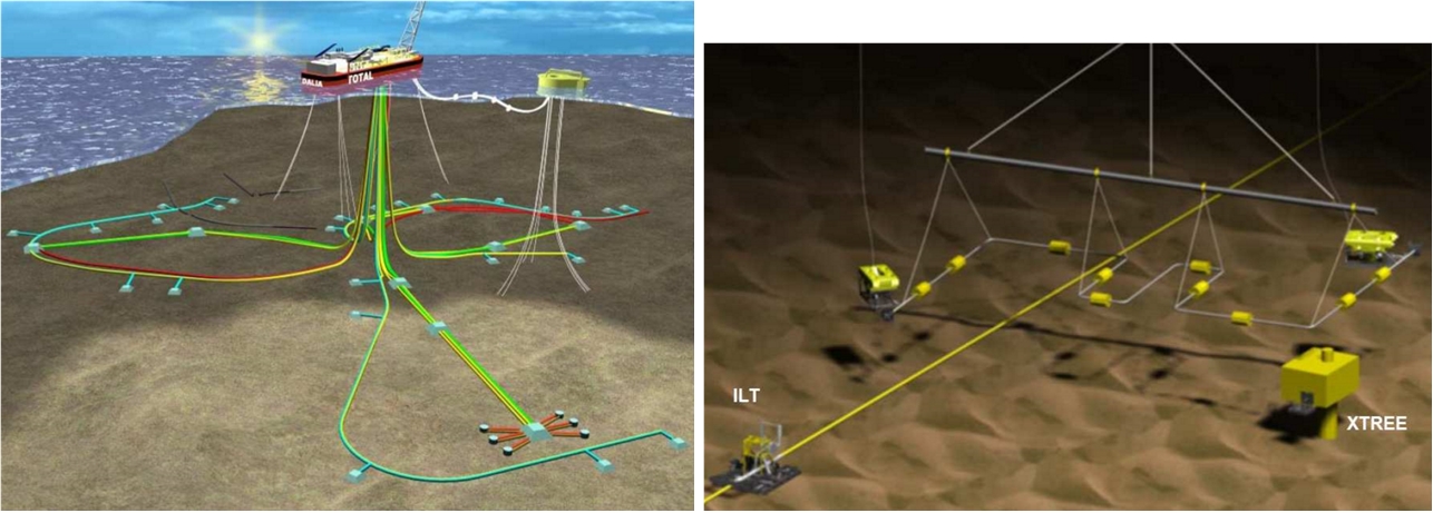
Among these methods, the rigid or flexible spool tie-ins have been the most implemented methods on recent deepwater projects. This is particularly true in West of Africa (e.g. Dalia, Bonga, Kizomba A & B, PAZFLOR, CLOV, KAOMBO) and Gulf of Mexico (e.g. Mardi Gras), where tie-ins can feature horizontal or vertical connections. However, all the methods have already been used and have some interests depending on the project type. However it shall be noticed that some of them are old techniques (Lay-down and Pull-in, Direct Pull-in, Deflect-to-connect) that are fast nearly not used anymore. The utilisation and limitations of each method are detailed in the following sections and the different advantages/drawbacks are listed in Section 6.
Tie-ins are mainly required between subsea structures such as:
Basically all diver-less and guideline-less connector systems (as reviewed in previous section) can be used to perform a subsea connection. However the selection of a tie-in method must be based on the following key topics:
Selected field subsea architecture (wells & manifolds layouts, flowlines routes, riser bases arrangement, etc.)
The water depth
The seabed conditions (i.e. soil type, visibility, current, etc.)
Hydrocarbon product temperature, pressure and chemistry
The selected connection technology (e.g. mechanical, electrical, monobore, multibore)
sealing reliability and ability to handle induced loads and moments (during installation, test and operations)
ease of installation and recovery and ability to make up misalignments (linear and angular)
The flowline types (i.e. rigid pipeline, wet insulated or pipe-in-pipe, flexible or umbilical) and its diameter
Availability and cost of the selected connector, tie-in tools, etc.
Greenfield or Brownfield (as existing tie-in system on field may influence selection of tie-in system )
Considered or imposed installation vessel (may impact jumper/spool design and conduct to select vertical tie-in rather than horizontal or inversely ), etc.
The SPS manufacturers, which can propose its own connection tool, adapted to its subsea production system and connector technology.
5.2 Rigid Spools and Well Jumpers
![[Tip]](tip.png) | Tip Click these links below for access to 3D resources: |
5.2.1 General
The term “jumper” (or "well jumper") is generally used when referring to connection system to Xmas trees, while “spool” is more used for the connection system between production flowline terminations (ILT/FLET/PLEM) and other subsea structures like Riser Base, GI or WI Xmas trees, manifolds, Multi-Phase Pump (MPP) module or other subsea processing unit (or as a general term for all types of subsea connections).
Connection's type | line's type | vessel(s) required |
Rigid and Flexible spools or jumpers | Vessel equipped with ROVs and adequate lifting means, e.g. crane, A-frame |
Rigid well jumpers are generally 20m to 30m long for direct tie-in of x-mas trees to flowline or via a manifold system.
Rigid spool pieces could be as long as 100m to 150m to perform flowline tie-ins to riser base structures (USAN, CLOV).
Flexible spool pieces can be as long as 100m to 300m (no specific technical length limitation) to perform tie-in to riser base (GirRi Phase 2, KAOMBO).
Spools and well jumpers are typically either ‘horizontal’ (Section 5.2.2, “Horizontal Tie-In System”) or ‘vertical’ (Section 5.2.3, “Vertical Tie-in System”) and these orientations applied to both spool planes and connector tie-in (or stroking) axis.
Innovative vertical ‘M’ spools and jumpers have been studied (e.g. Pazflor pre-project phase by SEAL Engineering) with the purpose of combining the advantages of the horizontal connection (manifold recovery by connector stroke-out) and ‘compact’ vertical ‘footprint’.
Conventional horizontal spools are either U-shaped or Z-shaped systems, 2D or 3D, as discussed in the following section.
5.2.2 Horizontal Tie-In System
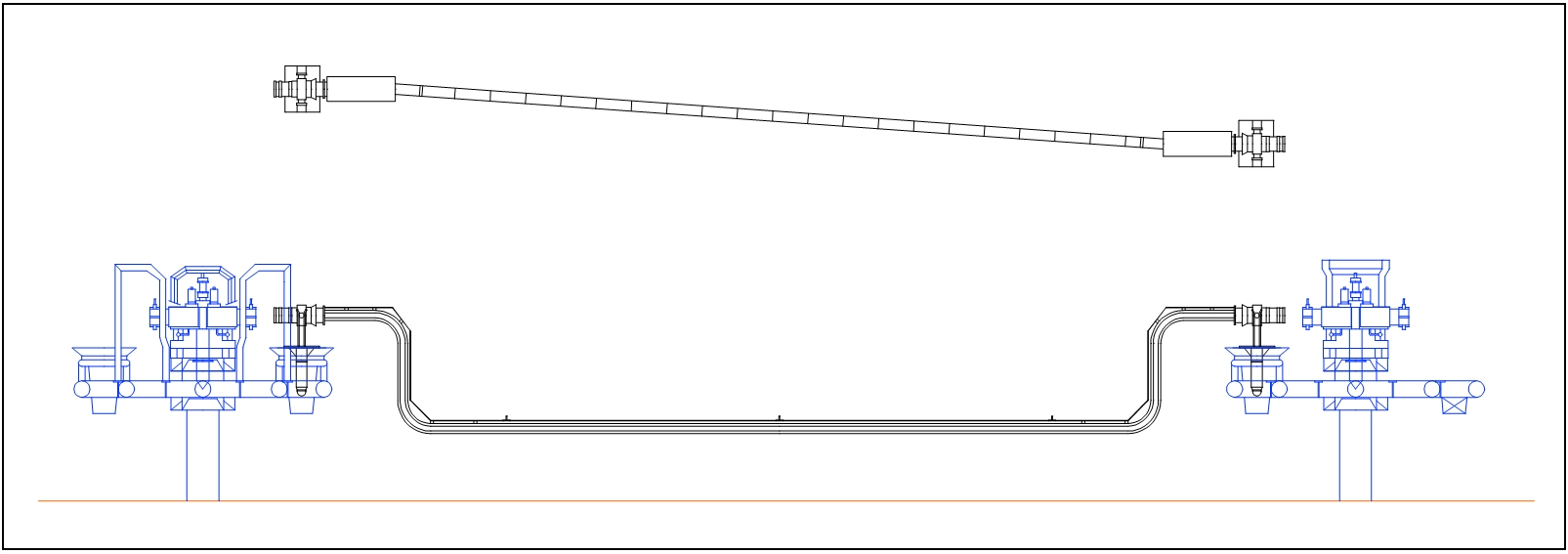
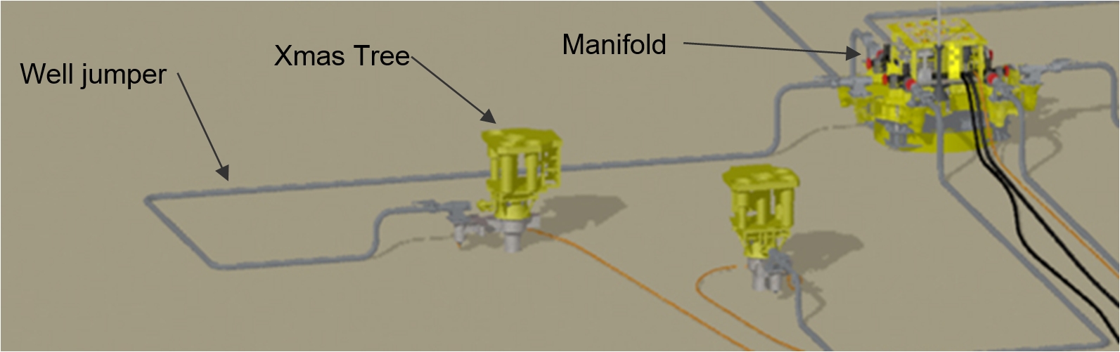
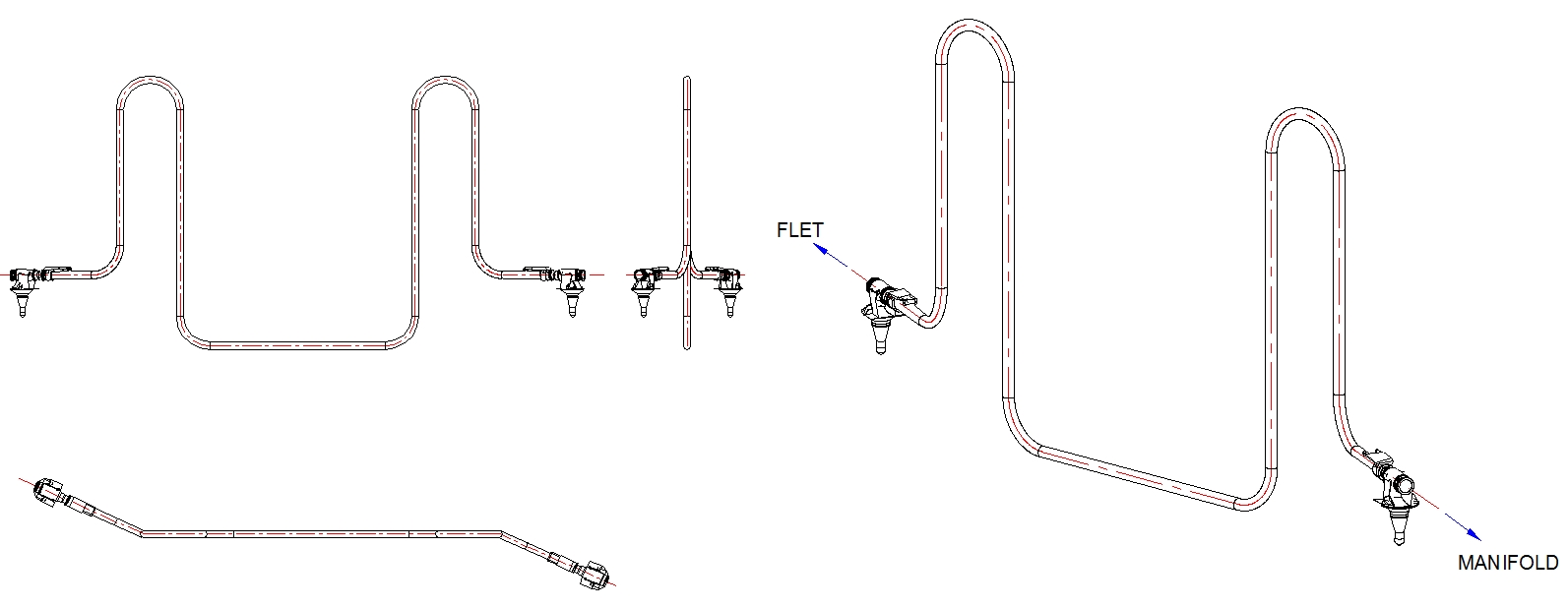
A spool/jumper configuration is called “horizontal” when the spool is positioned in the horizontal plane. The following figure shows a typical horizontal production well jumper, which is deployed and stab into the subsea receptacle structures. S-bends at each end of the jumper enable the jumper to be supported by the seabed soil.
Figure 5.3 - Horizontal Jumper between x-mas tree and manifold (e.g. Girassol, Rosa Lirio, Moho Bilondo)
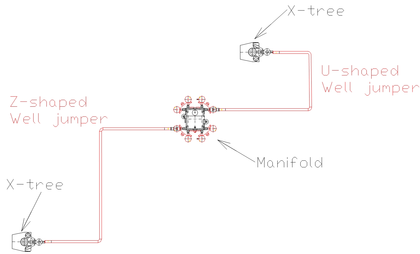
U versus Z jumper
The two classical configurations for the well jumpers are U-shape (as presented in Figure 5.5, “U-shaped well jumper installation based on supply boat and drilling rig crane (Girassol)”). and Z-shape (as presented in Figure 5.6, “Z-shaped well jumper installation using construction vessel heavy lifted crane (Girassol)”). The following figure presents the U and Z configuration for production well jumpers.
U shaped spools are generally not used for flowline to manifold tie-ins, due to flowline lay pattern and footprint at the manifold/wells cluster area.
Both of these configurations have been recently used on West Africa deepwater projects. The Girassol experience can be used to illustrate the different aspects of each configuration (see following pictures).
Figure 5.5 - U-shaped well jumper installation based on supply boat and drilling rig crane (Girassol)
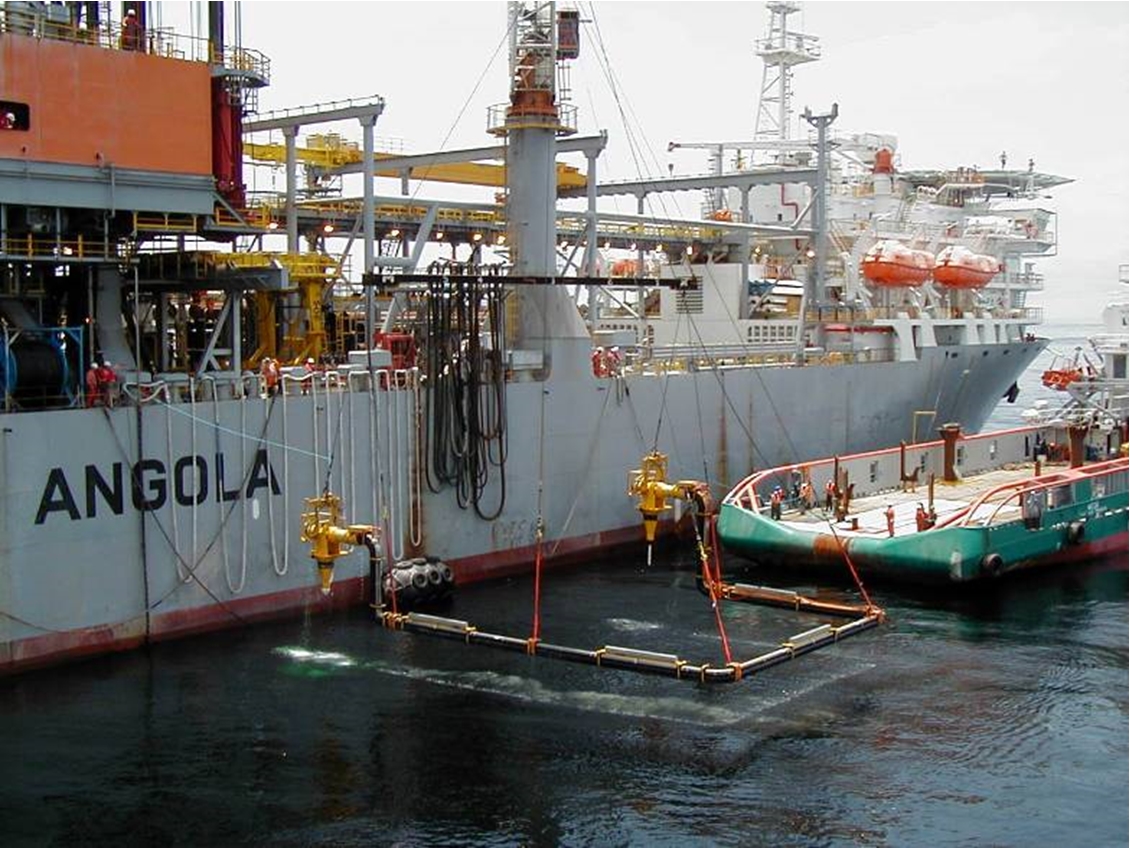
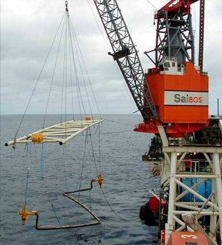
Figure 5.6 - Z-shaped well jumper installation using construction vessel heavy lifted crane (Girassol)
It can be seen that for Z-shaped jumpers, the two connectors are stroked in reverse directions (inducing stress in the jumper), while for U-shaped, stroking of the two connectors is in the same direction.
The following figure presents both ‘equivalent’ U and Z shaped injection well jumpers based on Girassol design data and functional requirements. The well jumpers presented are the “minimal well jumper” configuration, which corresponds to the shortest distance between the flowline (in-line tee) and injection Xmas tree, while maintaining sufficient flexibility to withstand the enforced displacements (e.g. thermal expansion, connector tie-in stroke in or stroke out), etc.
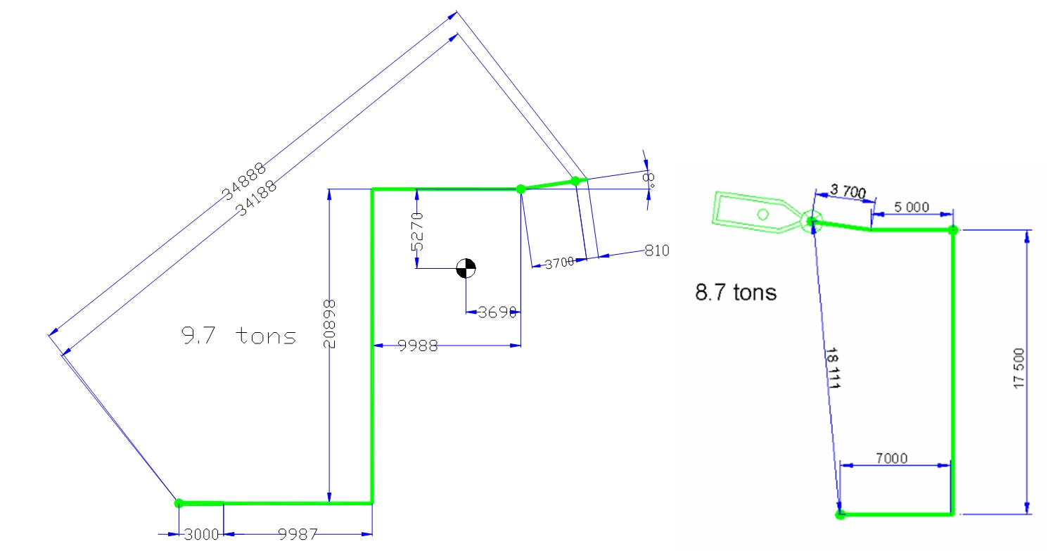
It can be seen that the Z-shaped jumper is significantly longer than U-shaped jumper, for the same functional requirements.
Due to spool geometry, special rigging incorporating a spreader beam (Figure 5.6, “Z-shaped well jumper installation using construction vessel heavy lifted crane (Girassol)”) is required to take connector loads without overstressing the jumper. For the Z-shaped jumper, rigging requirements are even more stringent with respect to crane height and lift capacity (Figure 5.5, “U-shaped well jumper installation based on supply boat and drilling rig crane (Girassol)”) and require larger transportation and installation means, i.e. deck space, crane lifting capacities.
Based on the above arguments, U-shaped jumpers are to be generally preferred when compared to Z-shaped jumpers.
5.2.3 Vertical Tie-in System
A rigid spool/jumper system is called “vertical” when it is positioned in the vertical plane. Vertical spools/jumpers are typically deployed directly and stab onto the subsea structure hub connectors.
Figure 5.8 - Various vertical connection spool/ jumpers, by courtesy of Schlumberger/ Nexen Petroleum (left - Aspen field, GoM) and FMC (right)
Vertical spools are typically designed in free span configuration. It is not necessary to rely on seabed soil support to maintain the spool integrity. This is a benefit (1) as the design does not rely on soil characteristics and bathymetry data and (2) in the case of flowline crossing.
The deck area required for transportation of a vertical system is significantly less than for the equivalent horizontal spool/jumper. It will usually be possible to fit several spools on the transportation vessel deck simultaneously.
For recovery of a xmas tree, the vertical well jumper connections must be broken at both ends, and the well jumper recovered to surface or subsea stored. The other way for well jumper to remain in place when the xmas tree is recovered is to incorporate an additional intermediate connection via the flow base. This solution requires an additional connection (xmas tree to flow base) for each well, which is considered to be an important disadvantage. For recovery of a manifold, all well jumpers and tie-in spools at the well centre must be disconnected and recovered to surface.
5.2.4 Horizontal vs Vertical Spool/Jumpers
The main advantages of a vertical tie-in system in comparison with horizontal systems are as follows:
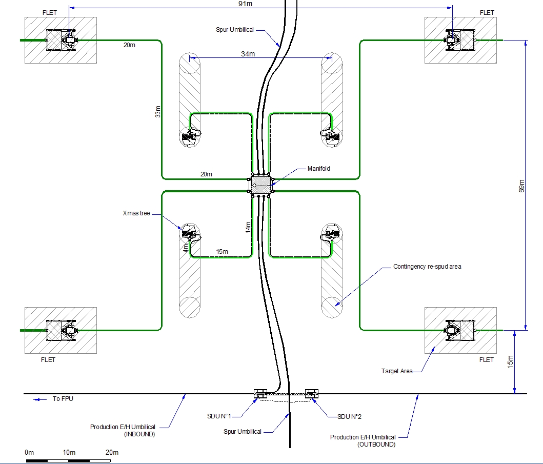
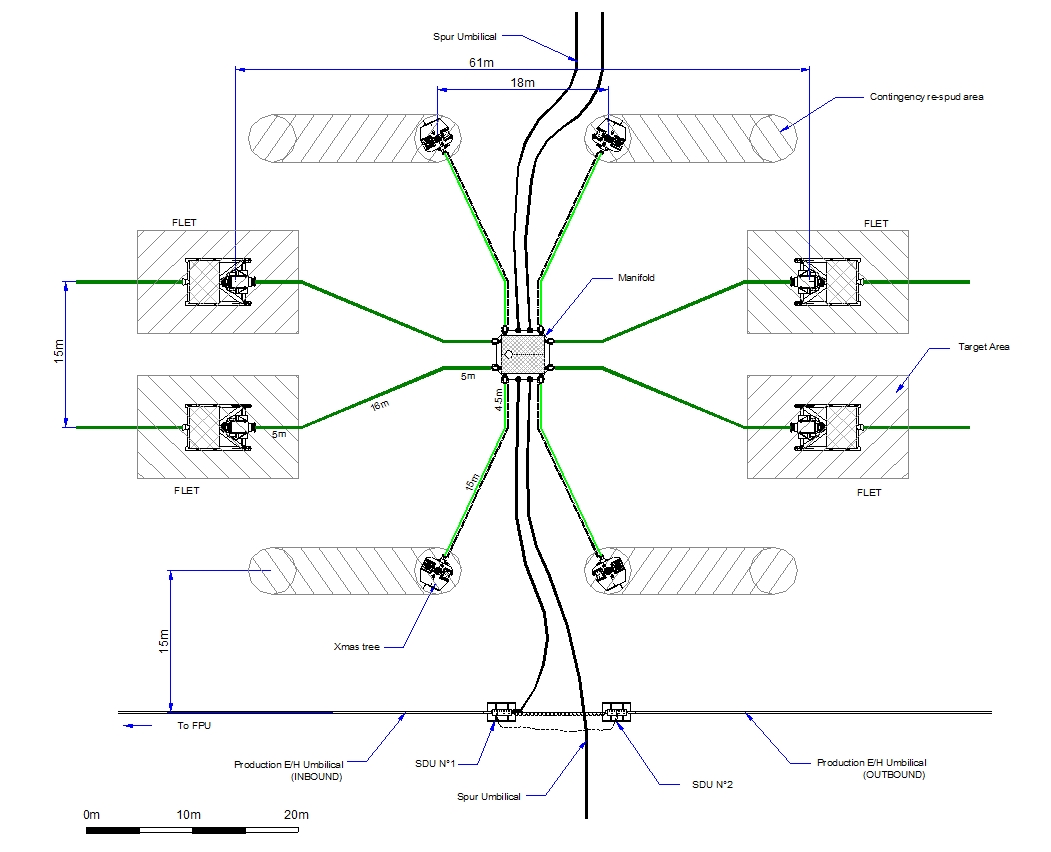
Vertical spools allow a simpler and more compact drill centre layout (refer to Figure 5.10, “Typical drill centre layout with horizontal spools and jumpers” and Figure 5.11, “Typical drill centre layout with vertical 'M' jumpers and spools.”).
Vertical spools are easier to fabricate, transport and install (less stringent requirements than for horizontal spool in terms of deck space and crane capacity).
Lower pull-in force (if any as some vertical connections are designed for hard landing on inboard hub with use of stroke tool only as contingency or for stroke out operation).
Minimise make-up forces and moments at ends
Vertical connection tools design and deployment are simpler
Vertical spools are installed with free spans, which avoid (1) any interface with the soil (e.g. no reliance on bathymetric accuracy and soil characteristics) and (2) the need to prepare any flowline crossing preparations, e.g. sleepers, mattresses.
With vertical connections, there is less potential for disturbance of seabed, and therefore mud-mats are not required and there are fewer problems due to poor visibility.
The main perceive disadvantages of vertical tie-in systems are as follows:
For recovery of a xmas tree or manifold, the vertical spool/jumper connections must be broken at both ends, and the spool(s) recovered to surface or stored subsea. While the consequences of a manifold (Pazflor Manifolds are equipped with vertical connections) recovery are severe in the case of a vertical connection, it is not expected that this would be a frequent event, particularly as hydraulic distribution systems may be recovered separately.
Require more accurate metrology (vert. connect. placed directly on final alignment structure)
Risk of damaging the seal is higher with vertical connection as connection is done in operation
Not adapted solution where trawling risk is high (NCS, UKCS, etc.)
Can experience more vibrations due to ViV than for a horizontal rigid jumper/spool.
Require favourable sea-state for transportation offshore at the installation site.
Vertical connectors generally exposed to higher torsional loads as a result of the connector orientation.
Flow assurance – the high points in the spool/jumper above the vertical connector could be a location for accumulation of gas. However, while it is desirable to minimize high and low points, local gas accumulations in the system cannot be eliminated with any degree of certainty, so cool-down calculations must be premised on gas filled pipe.
Flow assurance - Vertical bends induce risk of pressure build-up and slugs formation.
In general terms, the vertical tie-in system offers cost advantages for fabrication, transportation and installation phases, but there are of concern during the operation (and maintenance) phase.
Preliminary designs are available on innovative vertical ‘M’ spools and jumpers, featuring geometry contained in a vertical plane combined with horizontal connection method. The purpose of this alternative is to combine the advantages of the horizontal connectors (e.g. manifold or tree recovery by connector stroke-out) and ‘compact’ footprint, as further illustrated in Figure 5.9, “Vertical ‘M’ shape Spool featuring Horizontal Connector (typical)”.
5.2.5 Tie-in Procedure
Accurate measurements are required before rigid steel jumper fabrication, either on shore or on board the laying vessel (or barge, etc.). These measurements aim to define the relative position of both spool/jumper end future locations (distance and inclination between the two connection points) in order to define its final dimensions and to allow rapid and hazardless installation.
These measurements are generally obtained by acoustic array or occasionally by taut wire metrology (see Section Chapter 7, Hot-Tap Tie-in "Subsea Metrology").
The main phases for a rigid spool/jumper fabrication and installation are described below:
When the subsea structures or flowline terminations have been laid over the seabed, their position is determined using acoustic transponders in order to:
Check that they were laid within the target boxes (e.g. 5m x 5m)
Determine an approximate spool length for pre-fabrication. That allows, if the spool is fabricated offshore, to perform some cuts and weld operations during a non-critical period of vessel utilisation (e.g. during flowline hydrotest) and thus to reduce the final spool/jumper fabrication time.
Accurate measurements of the spool length and of the elevation (x, y, z) and orientation (3-axis) differences between the two connection points are performed. This can be done by one of the following systems (see Section 7):
After conversion of the detailed measurements into cut points, lengths and isometric drawings, the final spool fabrication can start.
Fabrication jigs are used for the spool/jumper geometry check and fabrication stands. The jigs are set up based on the measurements taken subsea and mock the spool/jumper receiver structures in order to verify that the spool would mate with them.
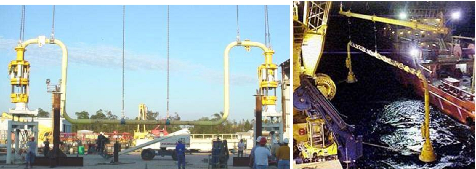
The spool is then transported, lowered to the seabed and connected. This can be done by using a spreader bar and the stab and hinge over method (or other tie-in method) which consists in:
Lowering the spool vertically
Stabbing one extremity of the spool
Stabbing the other extremity
Performing the connection by ROV mounted tool or light modular tie-in tools
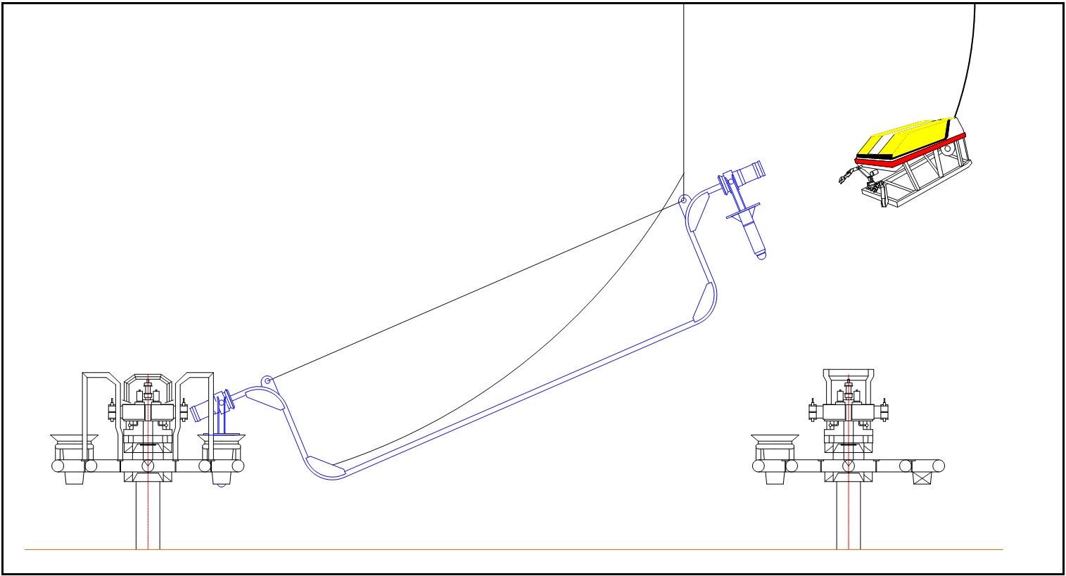
Figure 5.13 - TOTAL Girassol field, rigid steel jumper installation (spreader bar, horizontal connectors)
5.2.6 Utilisation and limitations
No diameter or water depth limitations have been identified or to be expected.
The main advantage (see Chapter 6, Advantages & Disadvantages "Advantages and Disadvantages") of the steel jumper is its economical aspect when combined with stringent heat insulation requirement. This point suffices to explain its extensive use in the Gulf of Mexico and West of Africa deepwater developments.
5.3 Flexible Spools, Jumpers, Spur Lines
5.3.1 Description
Connection's type | line's type | vessel(s) required |
Rigid and Flexible flowlines Umbilical | Vessel equipped with ROVs and lifting capacities |
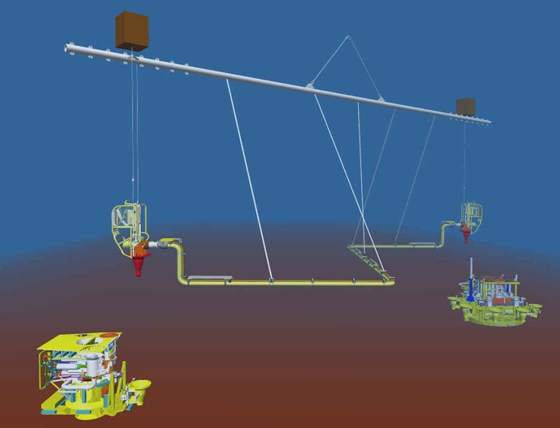
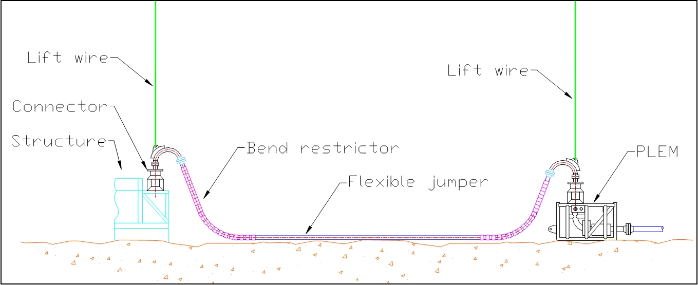
The principle of this method is to perform the link between two subsea structures (tree and manifold) or between a subsea structure and a flowline end termination (PLEM) by means of a flexible jumper. The distance between the two connection points, and hence the length of the jumper, is conventionally about 20m - 100m (i.e. within most medium size vessel lifting capacity).
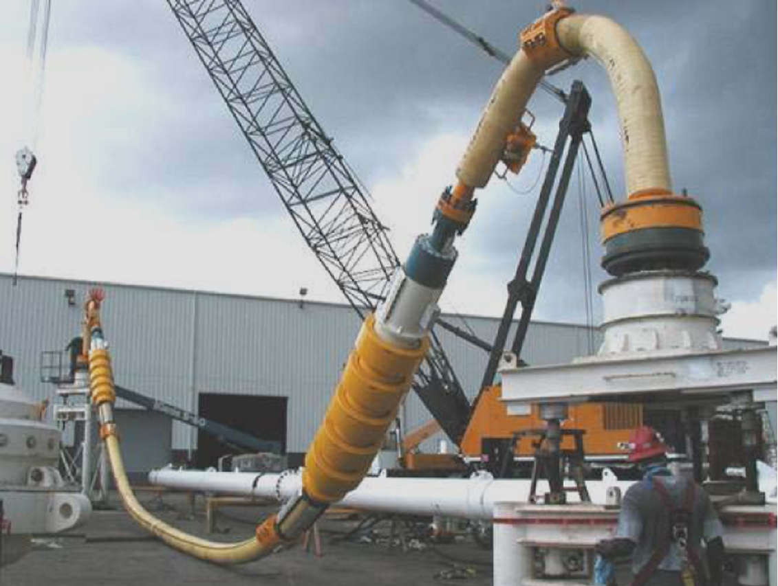
Figure 5.15 - Flexible jumper fitted with vertical connectors (Aspen field, GoM), by courtesy of Nexen Petroleum
5.3.2 Tie-in Procedure
Flexible spools/jumpers can be used for vertical or horizontal connection method. The flexible spool installation method depends on the connector type but it can be basically equipped with:
Horizontal connector (e.g. collet or clamp connector), the spool/jumper is typically laid down on the seabed in a pre-determined area and then connected by the pull-in method (pull-in technique is not widely used anymore)
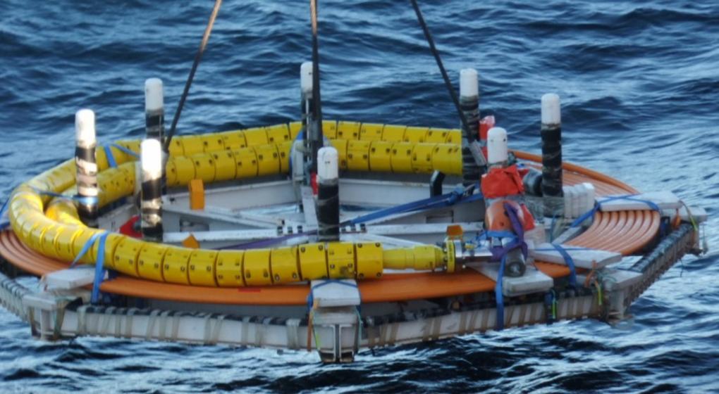
Vertical connector (e. g. collet or clamp connector), the spool/jumper is typically installed with a spreader bar and upward facing vertical connectors located on the subsea structures.
Vertical stab and hinge over method can also be used; this type of tie-in was utilised to perform the connection of flexible spool for Shell's Rocky field: the first end was equipped with a "Stab & hinge over" type hub and the second end included a vertical collet connector. After landing and locking of the first end, the second end was connected.
This tie-in method is dependent on ROV operation for all phases from guiding, landing, stroking to connection, tie-in actuation (clamp or collet fingers actuation) and leak tests.
5.3.3 Utilisation and Limitations
Flexible spool/jumpers are effective means to perform the connection between flowline end termination and subsea structure or between two subsea structures (i.e. tree and manifold).
Flexible spool/jumpers allow to withstand some imprecision in the position of line ends or subsea structures (and the potential flowline thermal expansion); thus there is no drastic requirements concerning subsea metrology (unlike rigid spool/jumpers) and it is sufficient to position pipeline termination head and/or subsea structure within less stringent target boxes.
Flexible spool's diameter and water depth limitation are dictated by the flexible technology. The use of flexible spools for deepwater applications would be limited mainly by economic consideration.
5.4 Thermoplastic Composite Pipe (TCP) Spools andJumpers
Use of composite is developing in the subsea oil & gas industry. One of the main applications is the use of composite jumpers or spools.
Composite due to its light weight, high strength and resistance to corrosion, sour service and fatigue loading have following advantages for jumpers spools application:
simplified spool design,
simplified subsea installation procedures and operational activities,
No corrosion issue (except at bend stiffener and connector),
reduced need for inspection, maintenance, repair or replacement.
Lower procurement, installation and OPEX cost.
Depending on manufacturer (MAGMA, Airborne Oil&Gas, etc.), the composite Jumper Spools are installed either on a subsea pallet, horizontally with two cranes, vertically with one crane, through a spreader bar or conventional vertical lay system.
Both MAGMA and Airborn Oil&Gas have completed qualification program of their composite jumpers/spools in accordance with the standard DNVGL- ST-F119.
Airborn Oil&Gas | MAGMA Global | |
Diameter | Up to 7.5 inch ID | all diameters from 1.5 inch methanol jumpers up to 12 inch production applications, |
Temperature | 121 degrees C (250 F) | 2ksi up to 20ksi |
Working pressure | 10 ksi | High temperature capability for hydrocarbons, gas and water |
In January 2019, TOTAL has awarded Airborne Oil & Gas B.V. with a contract to supply a 5.2” ID, 370 bar design pressure TCP (Thermoplastic Composite Pipe) Jumper for water injection for a deepwater project in West Africa located approximately 150 km offshore in water depths of up to 1600 m. The TCP Jumper will be terminated in country and installed using a subsea pallet, deployed from a small vessel.
5.5 Flying Leads
Refer to section 17.8 and 17.9 of Subsea Control Systems Deepwater reference book [104].
5.6 Lay-down & Pull-in
5.6.1 Description
Connection's type | line's type | vessel(s) required |
Flowline - Subsea Structure | Flexible lines Umbilical |
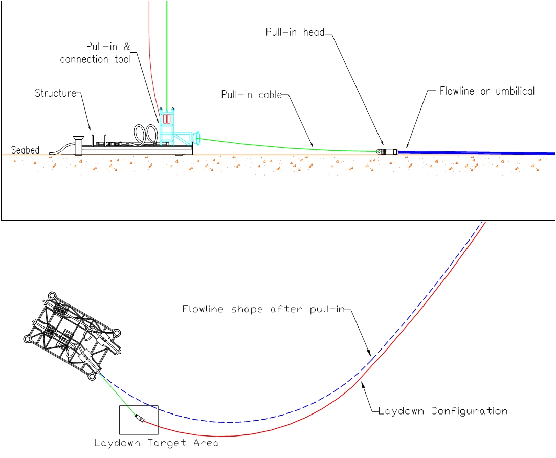
The lay down and pull-in method consists in pulling in and connecting a flowline or umbilical, laid down on the seabed in a predetermined target area, to a subsea structure (X-mas tree, manifold, riser base).
This method is effective for both first end and second end extremity connections of flowline to subsea structure. Typical pull-in force expected for such an operation is about 5-10T, depending on the line type and soil conditions (friction coefficient) and a pull-in distance to be limited to less than 50m.
5.6.2 Tie-in Procedure
The lay down and pull-in operation can be divided in three main phases:
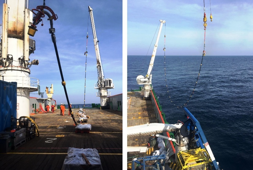
The flowline or umbilical end extremity (first or second end) is equipped with a pull-in head. The termination head is laid on the seabed within a pre-determined target area by a lay vessel. Several laying configurations can be adopted near the connection point:
Flowline approaching the structure along a straight-line oriented towards the connection point but with sufficient downstream loop for future pull-in operation.
Flowline laid in curve near the structure (flexible or umbilical lines) in order to decrease the pull-in tension.
Off-centred straight-line configuration in order to perform a lateral deflection during the pull-in operation.
The pull-in operation could then be performed by a smaller vessel (i.e. tie-in vessel) equipped either with an ROV-mounted pull-in tool or an ROT/pull-in system remotely operated from surface tie-in vessel. The pull-in tool function is to place the line's hub connector closed to the subsea structure's hub (it generally includes a guiding device such as a funnel, to perform a rough alignment) and to prepare the connection operation (the debris cap is retrieved, etc.):
with an ROV-mounted tool: the tool package is fixed on ROV which then attaches the pull-in rope on the subsea structure pull-in porch, clamps itself on the pull-in head of the flowline and performs the pull-in operation. When the head is closed to the connection point, ROV prepares the hubs (debris cap removal, etc.) and performs the connection prior to the seal test performing.
with a Remotely Operated Tool: the pull-in tool is lowered and fixed on the subsea structure; ROV attaches the pull-in rope, then the line's head is pulled toward the connection point and aligned at the final stage by guiding devices on the tool. After the pull-in operation, the connection is performed if the tool is a two-tool system, otherwise the pull-in tool is recovered on-board and the connection system is lowered.
Finally the line is connected to the subsea structure with:
The connection is typically performed by means of collet connector or clamp connector in combination with a seal (or seal plate in case of multibore configuration: umbilical or prod line with service, chemical and hydraulic lines). External leak tests (nitrogen or hydraulic) are then performed by ROV or ROT means to check the connection.
5.6.3 Utilisation and Limitations
The lay-down and pull-in method has been extensively used in most oil provinces but mainly for shallow water depth applications (200 - 400 msw). Petrobras has experienced this method with no satisfactory results (i.e. near seabed ROV operation on soft soil).
The ROT based connection systems utilising a surface-operated winch become unsuited as the water depth increases due to the number, lengths and weights of lines running from surface (lifting line, pull-in cable, controlled umbilical, etc.).
For deepwater operation, the ROV-mounted tools (e.g. Flexconnect, RTS) are better suited.
The “lay down and pull-in” method requires good seabed conditions:
Good visibility for cameras (and ROV manoeuvring) near seabed
Seabed clear of any debris or obstructions within the pull-in pattern
Low soil friction coefficient to ease the pull-in operation, but still consolidated soil bearing to prevent pull-in head ‘diving’ into the mud-line.
This tie-in method is therefore not recommended for deepwater connection in the case of very soft soil conditions (i.e. 5-15kPa) and poor visibility near seabed.
5.7 Direct Pull-in
5.7.1 Description

Connection's type | line's type | vessel(s) required |
Flowline - Subsea Structure Riser - Subsea Structure | Rigid pipeline Flexible line Umbilical | Combined operation of Laying vessel and Tie-in vessel equipped with pull-in tool |
The direct pull-in method consists in connecting a flowline or an umbilical to a subsea structure (manifold, tree) by pulling it directly to the tie-in point in order to:
Initiate the laying operation. The line is pulled off the laying vessel to the subsea structure, latched and then the laying vessel continues the laying operation. The connection is then performed when the laying sequence ends.
Or connect a flowline that has been towed from an onshore fabrication yard. The pull-in is performed to help controlling the lowering of the line and allows adjusting the first end position to perform the connection.
For the pull-in, a cable coming from a surface winch or subsea winch can be used and then the connection is performed by a separated tool.
This method is effective for first end tie-in of umbilical, flexible and relatively small diameter rigid line.
5.7.2 Tie-in Procedure
The main phases of a direct pull-in can be described as follows:
Setting of the pull-in tool on the subsea structure
Attachment of the pull-in cable which runs from the pull-in tool to the flowline to be laid and connected.
Flowline laid initiation: the flowline is pulled towards the subsea structure while being paid out from the laying vessel. The catenary curve is controlled by monitoring the flowline pull-in head position, by means of transponders, and tension in order to avoid any buckling problem.
When the flowline pull-in head arrives at the subsea structure, the pull-in tool latched it, allowing the start of the flowline lay-away phase.
The connection is then performed by the appropriate tie-in tool(s).
5.7.3 Utilisation and Limitations
The direct pull-in method allows performing the initiation of a flowline without using a PLEM and initiation anchor point as the subsea structure is used as an anchor point. This involves taking the pull-in loads into account for the design of the structure.
This method is very effective for flowline initiation with however two main drawbacks (see Section 6 "Advantages and Disadvantages"):
It requires the availability and good coordination of two vessels.
The connection (at the subsea structure) cannot commence until the end of the laying operation and the flowline is “pigged”, flooded and hydro-tested.
The “Direct pull-in” method is limited by the design maximum water depth operability of the pull-in tool and has been used on Nork Hydro TOGI for up to 24" rigid sealine.
5.8 Deflect-to-Connect
5.8.1 Description
Connection's type | line's type | vessel(s) required |
Flowline - Subsea Structure | Rigid flowline | ROV support vessel with adequate subsea lift |
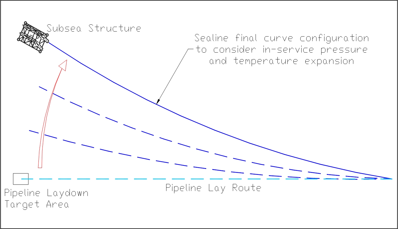
This method consists in lifting a defined length of a pipeline (typically 500m – 800m) by means of subsea buoys, deflecting the flowline end near the structure with a vessel or subsea winches and finally pulling the flowline into the subsea structure in order to perform the connection.
The deflect-to-connect method is effective for rigid pipeline tie-in to a subsea structure. The pipeline must have been laid along an off-centred straight line near the subsea structure prior to the deflection (typical distance 100m – 200m).
5.8.2 Tie-in Procedure
After the flowline has been laid on the seabed, a typical deflect-to-connect operation can be performed as follows:
During the preparatory works (pipe as-laid survey, debris removal, etc.) air bags (or buoyancy elements) are fixed to the pre-installed collars (Troll Olje export lines project) and inflated in order to lift a pre-determined pipe length (fixed by the required final curvature) for future deflection. Drag chains (installed during pipelay operation) spread along the lifted length are used to control the height of lifting and the pipeline curve stability during the deflect operation (by varying the chain length friction onto the seabed and so controlling the drag forces at different points of the deflected length of pipeline). The deflected length is also equipped with transponders to check the elevation and the pipe curvature during the deflect operation.
As an example, about 15 air bags and 5 transponders were spread along the 400m – 500m of deflected pipeline on the Troll Olje project.
The flowline is deflected:
either by a vessel which displaces a dead weight attached to the pipeline extremity toward the subsea structure (Elf East Frigg and Norsk Hydro Troll)
or by subsea winches mounted on the subsea structure (R.J. Brown method)
This is done by steps of approximately 10-20m until the pull-in head is in front of the subsea structure; the pipeline curvature is checked at each step by means of transponders and compared to the theoretical values (e.g. the minimum bending radius and line tension must always be controlled to avoid any local buckling).
When the pull-in head is in front of the subsea structure, a pull-in and connection operation is performed by ROT:
after the pull-in operation and once the pipe is secured inside the subsea structure, the pipeline can be flooded
on completion of pipe flooding, the connection can be performed
on completion of the tie-in task, all installation riggings are recovered (chain, buoyancy elements, etc.)
5.8.3 Utilisation and Limitations
This method is mainly used to connect large diameter rigid pipeline because of the difficulty to manipulate and connect them with another method. The flowline final curve must also consider the service conditions, in terms of thermal expansion, possible slugs, etc. Besides these technical issues there is no foreseeable limitation for deepwater applications. Several diverless deflect-to-connect operations have been successfully performed including the two 16" ID export lines on Norsk Hydro Troll B project (in 1994) and the two Elf East Frigg 24” bundles (in 1988).
5.9 Vertical Stab, Hinge-Over & Lay-away
5.9.1 Description
Connection's type | line's type | vessel(s) required |
Flowline - Subsea Structure Riser - Subsea Structure Umbilical - Manifold | Small diameter rigid pipeline Flexible line Umbilical | Separated operations:
|
This tie-in method is used to initiate flowline or umbilical first extremity by stabbing and latching it (by means of a hinged torpedo) in a receptacle (i.e. funnel) mounted on the subsea structure foundation (manifold support structure MSS, XT Permanent Guide Base PGB, PLEM). The connection is performed after the laying operation by means of an ROV-mounted connection tool (see Section 4.4, “ROV-mounted Connection Systems”).
5.9.2 Tie-in Procedure
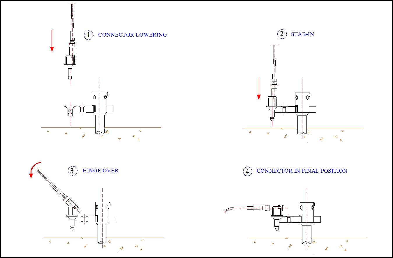
During the flowline (vertical) initiation its first extremity is lowered and latched to the subsea structure by the stab and hinge over method (Figure 5.21, “Vertical Stab and Hinge Over principle”):
The stab and hinge over assembly is connected to the line (flowline or umbilical) and a transponder is attached to monitor the line termination during initiation.
The assembly is lowered at the vertical position of the subsea structure receiver. While setting up in DP over the tie-in point, the laying vessel continues to pay out the line. The stabbing of the assembly into the receptacle funnel mounted on the subsea structure is performed; the final approach is assisted by ROV. An orientation helix in the receptacle rotates the head into the proper rotational alignment for the hinge over.
When the assembly is fully engaged and locked in its receptacle, the laying vessel moves away slowly while paying out the line until the line is correctly landed on the seabed. The laying operation continues.
At completion of the laying operation (i.e. pipe flooded), the connection (by a tie-in vessel) is performed by stroking out the outboard hub that is retracted during the stab and hinge over operation and then connecting it to the subsea structure (see Section 4.4, “ROV-mounted Connection Systems”).
5.9.3 Utilisation and Limitations
This tie-in method is effective for rigid, flexible and umbilical lines but attention must be paid to the rigid line stabbing and initiation loads. A minimum flexibility of the line is required during the stab step of the method, particularly if no heave compensator is used.
This method is probably the most cost effective solution to perform the first end initiation and tie-in for deepwater applications. No water depth limitation is expected (i.e. the only limiting factor is the connection tool maximum water depth operability).
The only limitation is with large diameter rigid pipeline due to potential high load on the subsea structure during the stabbing and hinge-over phases, although passive heave compensated tensioners would annihilate this limitation.
This method has for example been used to connect 6" flowlines and umbilical to manifold on the Shell's Mensa field (1620m); hydraulic connectors powered by ROV via an ROV interface panel were used.
5.10 Surface Tie-in, Lay-away or Lay-to
5.10.1 Description
This method, developed by Petrobras, was used up to 1992 and was then replaced by the vertical stab and hinge-over connection method (see Section 5.7).
Connection's type | line's type | vessel(s) required |
Flowline - Subsea Tree Riser - subsea tree | Flexible flowline Umbilical | Combined operations with a Laying vessel and a Drilling rig |
The lay-away and lay-to surface tie-in method is effective to connect first or second end of a flexible and umbilical lines to a subsea tree.
This method consists in performing the connection between the lines and the X-mas tree on-board a drilling rig prior to the lowering of the assembly.
5.10.2 Tie-in Procedure
The lay-to or lay-away methods, which have been primarily developed by Petrobras to improve existing pull-in methods, can be described as follows.
The lay-away tie-in procedure can be divided in five main phases:
After arriving on location, the laying vessel positions itself approximately 30m away from the drilling/completion rig. A cable is passed from the rig to the laying vessel (e.g. by means of a messenger line) and attached to the flowline(s) (the number of flowlines depends on the laying vessel capacity) first extremity equipped with a pulling head.
Each flowline first extremity is transferred to the rig by paying out the line while pulling the cable according to a predefined sequence.
When the predetermined catenary curve is achieved, each flowline first extremity is connected to the subsea tree on-board the drilling rig. The assembly is fully tested, allowing potential problems (e.g. leaks, monitoring) to be solved prior the laying operation.
The tree and the flowlines are then lowered simultaneously. The tree is landed and connected.
When the connection is pressure tested, the lines lay-away can commence towards the production floater.
The lay-to operation uses the same methodology:
While laying the flowline(s), the laying vessel arrives near the drilling/completion rig. When the line(s) second extremity is fully secured on the working table of the laying vessel, a transfer cable is passed from the rig (e.g. by means of a messenger line) and attached to it. The flowline second extremity is transferred to the rig by lowering it by means of an abandonment cable while pulling the transfer cable according to a predefined sequence.
A second option is that the line is lowered by the laying vessel on the seabed in an extended loop arrangement and later recovered by the rig by means of a lifting cable attached to the flowline extremity by ROV. This method avoids the problem of the simultaneous presence of the laying vessel and the rig.
The flowline(s) second extremity is then connected to the tree on-board the rig. The assembly is fully tested, allowing potential problems to be solved prior the lowering operation. A cable (from the laying vessel) is then attached at a defined intermediate location on the flowline(s).
The drilling rig lowers the tree while the laying vessel retains the line(s).
As the drilling rig must be located at the vertical position of the well during the operation (if guidelines are used to install the X-mas tree), a flowline overlength (at least equal to the water depth) is required.
Once the tree is landed and tied-in, the vessel lays the overlength/loop on the seabed.
5.10.3 Utilisation and Limitations
The main advantages of this method (see Section Chapter 6, Advantages & Disadvantages "Advantages and Disadvantages") are clearly to allow the connection and all tests to be performed in surface.
The lay-away method was a standard for diverless connections in Campos Basin up to 1992 where some 57 lay-away operations, including 36 guideline-less operations, have been successfully conducted in water depths ranging from 280m to 1030m. Then the vertical subsea connection system (see Section Section 5.11, “Hybrid Steel Pipe & Flextail”) was developed to overcome its drawbacks (mainly the obligation of the presence of both drilling rig and laying vessel and also the fact that only connections to subsea trees are possible).
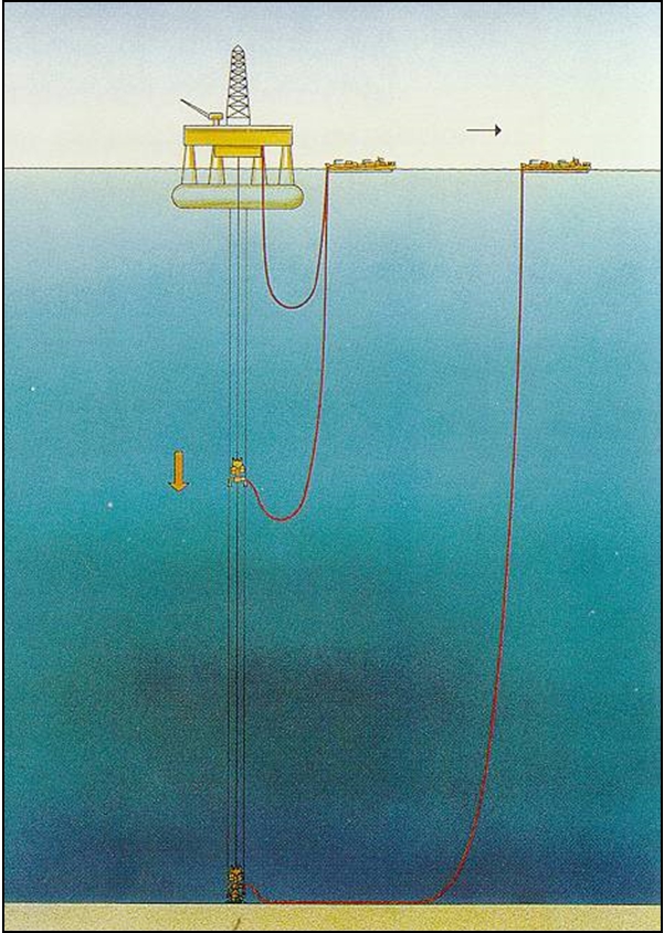
5.11 Hybrid Steel Pipe & Flextail
5.11.1 Description
Connection's type | line's type | vessel(s) required |
Flowline - Subsea Structure Riser - Subsea Structure | Rigid pipeline | Laying vessel |
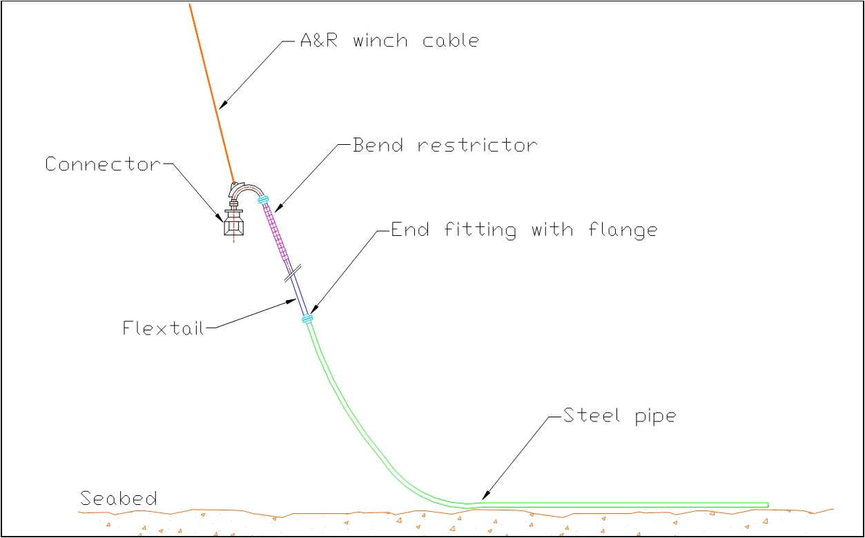
This method consists in integrating a pre-determined length of flexible pipe (spur line, flextail) to a rigid flowline end(s), thereby allowing handling more easily the extremities during the tie-in phase.
The methodology can be considered similar to the flexible jumper method, as a flexible line is used to perform the connection between a rigid flowline and a subsea structure, but the ‘flextail’ and the rigid flowline are connected together in surface, simplifying this part of the tie-in operation and allowing to perform external connection leak tests prior to the lowering of the hybrid pipe.
This method has been used mainly by Technip for Petrobras (Roncador) in Brazil.
5.11.2 Tie-in Procedure
The flextail is used to perform the connection between a rigid pipeline and a subsea structure. It can be installed as per one of the following methods:
The flextail can be installed as part of the rigid pipeline lay operation (initiation or lay-down phases) the flextail is directly connected on-board the laying vessel and then:
Either the flextail is connected to the subsea structure by the laying vessel, in subsequent operation,
Or the flextail is laid with its connector onto an abandonment skid to be later connected by a dedicated tie-in vessel.
The rigid pipeline is abandoned onto the seabed and later recovered for connection of the flextail prior to the final tie-in to the subsea structure or the riser base structure.
5.11.3 Utilisation and Limitations
An hybrid steel pipe and flextail can be used with the following restraints:
The rigid pipeline diameter is limited (e.g. 16”ID) as both flextail and rigid pipe must have the same internal diameter (e.g. pigging operation).
Flexible line must be designed for the considered water depth (i.e. reversed end cap effect: collapse of the steel armour under hydrostatic pressure) and the tension load induced by the rigid pipeline (air filled) during the abandonment operation.
Limitation is related to flexible pipe technology.


