
2 Intervention philosophy and functional requirements
2.1 General
Most of the contractor ROV and associated tooling are designed until 3000WD. The industry main effort is always focusing on improving the efficiency, reliability and flexibility of the systems. With deepwater applications, reliability becomes much more a vital factor for operation success and cost effectiveness. Priority is being given to increase the endurance of equipment so that the vehicle does not have to be brought back on deck for routine maintenance. The round trip from/to 2000 m can take more than 4 hours.
A better ROV availability can be achieved thanks to high risk ROV sub-systems provided with built-in backup systems in the event of failures. In most cases, the ROV will be able to continue the mission but with reduced (‘downgraded’) performance. The most recognised high risk sub-systems which are to be provided in dual mode are: dual FPU, dual motors, dual depth sensors, dual navigation compasses, multiple cameras, dual seven-function manipulators, multiple fibre optic data transmission, etc. It is reported from service companies that ROV reliability is significantly affected by umbilical and tether arrangements.
In addition to the adaptation of the existing tools to ultra deepwater applications, a current trend is to develop a complementary way and in particular the Autonomous Underwater Vehicle (AUV) technology to perform inspection operation. These un-tethered vehicles are capable of travelling along a pre-defined route gathering information and are now fully recognised as an efficient survey tool. AUV currently require surface vessel positioning support, so cannot travel along a pre-defined route independently (or autonomously). INS limitations also restrict performance, although this is improving.
The establishment of an intervention scope of work at an early stage of the ROV/AUV system design for a particular application allows to define the required types of ROV, AUV and the eventual ROTs (based on functional requirements), the associated equipment (i.e. tools) and then to manage the interfaces (i.e. with SPS, support vessel, etc.). With this objective, the intervention scope of work must be defined as soon as possible and the following points addressed:
The various tasks to be carried out (survey, drill support, SPS installation, IMR)
The surface support type of vessel (drilling rig, construction vessel)
Required types of tools (torque tools, hot-stab, etc.)
ROV (e.g. docking panel, working platform)
SPS accessibility requirements versus ROV dimensions, manipulator envelope)
Positioning support
Deployment support
Communication support
Vessel for AUV
Etc
Typical intervention / inspection tasks include:
Visual inspection and monitoring (e.g. pipe-lay)
Cable cutting
Measurements (metrology)
Component replacement (e.g. transponders, modules)
Template / tree intervention (e.g. valve operation and emergency override, valve maintenance and testing, etc.)
Umbilical and flowline tie-ins (e.g. pull-in and connection)
Spool or jumper installation & tie-ins
Pipeline trenching and burial
Rig assistance & prevention (High Flow Pump Skid Section 7.6, “High Flow Pump skid”) as BOP killer
etc.
The functional requirements are performance oriented and give the minimum criteria which must be satisfied in order to meet with stated objectives (e.g. to provide reliable ROV support to ensure cost effective and safe operation):
List of subsea tasks to be performed
ROV/AUV launch and recovery limitations versus weather window (sea state definition)
Available ROTs and/or ROV tooling (e.g. generally from the SPS manufacturer) to be interfaced to the ROV systems
Remote subsea intervention system availability or working rate
Contingency plan in case of failures (e.g. availability of spare parts, components, vehicle, umbilical, etc.)
Continuous improvement plan based on experience feed-back
AUV autonomy
AUV sensors compatibility with task
AUV positioning capability with reference to sensor capability
etc.
2.2 Intervention by ROV
2.2.1 Functional requirements
ROV is a compliant system which can perform various subsea tasks such as those quoted in previous section. Deepwater ROV design shall provide adequate equipment / tooling and the capacity to interface with the SPS design, with sufficient power (i.e. for tool implementation and propulsion adapted to the subsea conditions), depth capacity, etc.
Three main ROV configurations can be adopted to perform these subsea tasks:
The ROV spread shall be designed based on the modular concept for ease of transportation, handling, mobilisation and transfer onto different support vessels of opportunity.
2.2.2 ROV classification
ROV are typically grouped into about five categories, classified by role and/or size. IMCA R 004 Rev4 gives the following classification:
Class I – Pure observation ROVs.
Class IIA – Observation class vehicles with a payload option.
Class IIB – Observation class vehicles with light intervention/survey and construction capability.
Class IIIA – Standard work class vehicles with a payload of <200kg and through frame lift of approx. 1000kg.
Class IIIB – Advanced work class vehicles with a payload of >200kg and through frame lift of up to 3000kg.
Class IVA – Towed vehicles, typically ploughs used in subsea cable burial operations.
Class IVB – Tracked vehicles utilising HP water jetting and specialised rock cutting tools, again used in the burial of subsea cables and pipelines.
Class V – Prototype or development vehicles.
Class VIA – Autonomous Underwater Vehicles (AUV) weighing <100kg.
Class VIB – Autonomous Underwater Vehicles weighing > 100kg.
Class I Observation ROVs are employed for visual inspection / monitoring and diver assistance. These systems are typically fitted with light sensors, probes and a simple grabber but carry little or no payload. Most of the time these ROV are not designed to reach the deep water depth (Eye bolt or Obs ROV use to be deployed in free flying mode).
Class II ROVs are used for tasks ranging from inspection, observation and light subsea tasks. They can carry two cameras, sonar and a single manipulator arm; they are able to complete light payload tasks.
Class III Work ROVs are employed for various tasks such as drill support, construction and repair tasks, platform cleaning, subsea tool deployment and operations. They feature higher hydraulic power and payload capacity, more sensor channels and are generally fitted with either grabber or a seven-function manipulator arm (e.g. for drill support) or two seven-function manipulator arms (e.g. for construction tasks).
The Work ROV spread is based on the same design as the drilling support ROV, and as much as possible using the same components, control systems, equipment, etc for the purpose of ROV's pilot / technician training, familiarisation and maintenance aspects (e.g. same spare parts).
Class IV vehicles are typically much larger and heavier than Class III work class vehicles. Towed or bottom crawling are typically purpose built to a particular intervention task (e.g. subsea trenching or pipeline tie-ins).
Class V prototype or development vehicles include those being developed and those regarded as prototypes.
AUV is currently assigned to Class VI.
Each ROV must accommodate a wide variety of tooling, work equipment and sensor systems. Standardisation efforts of the equipment are performed, leading in particular to the API RP 17H recommendations.
2.2.3 ROV stabilisation methods
The intervention philosophy shall address the stabilisation method employed by the ROV (e.g. grasping bars, docking points, etc.) in order to be able to define the interfaces with the subsea structure and the ROV equipment.
The stabilisation can be achieved by means of the following:
Grab bars
Docking device
Working platforms
The ROV can grasp bars on the structure by means of a manipulator / grabber arm with parallel or pincer jaw. Adequate standard bars must be fitted onto the subsea structure, which shall resist the loads applied by the ROV as per API RP 17H.
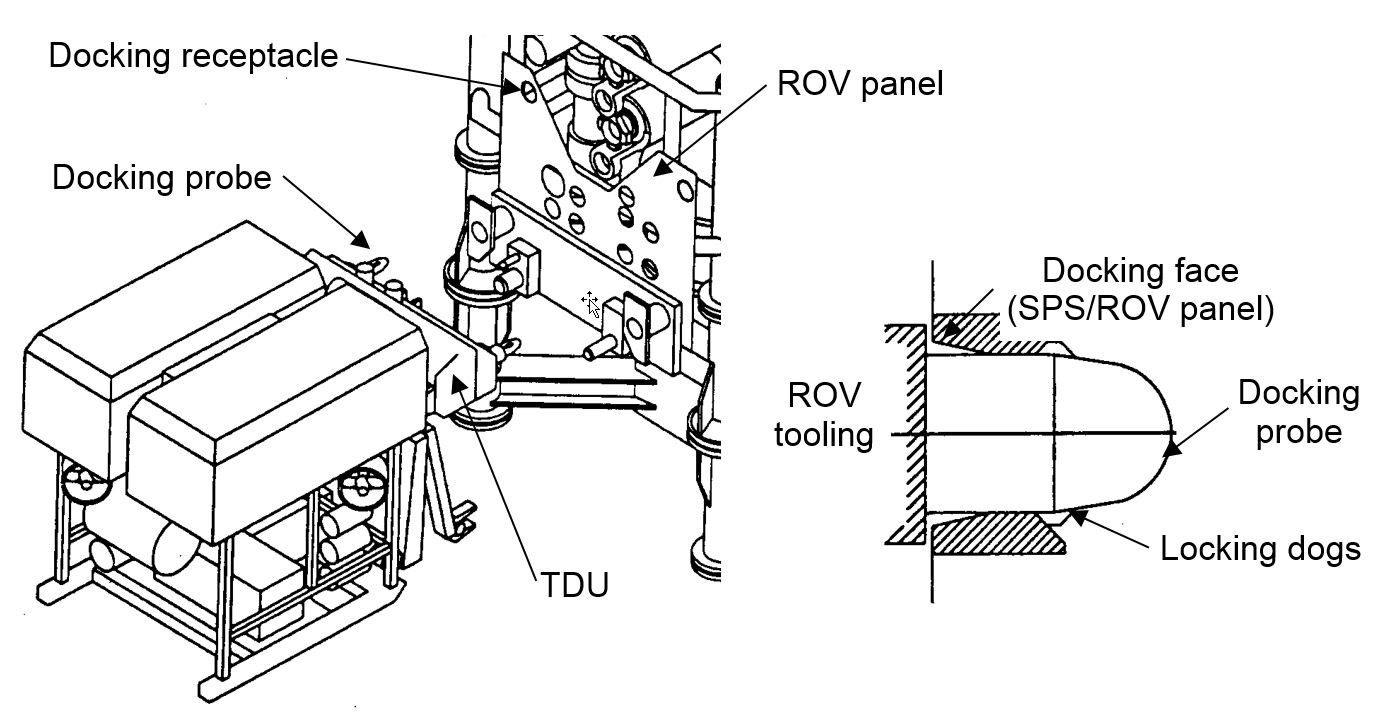
Docking is generally used in combination with TDU (see Section Chapter 7, ROV tools), but it can also be used during manipulator operations. It is convenient when the transmission of force to the working interface must be avoided (e.g. during operation involving hot stabs) or when heavy loads are handled (e.g. stab plate connection). Docking provides stable and accurate positioning of the ROV; it is performed by stabbing one or two docking probes in docking receptacle(s). The docking probe is a hydraulically operated device with locking dogs at its extremity, as depicted on Figure 2.2, “Docking principle with Tool Deployment Unit (TDU)”.
A working platform can be used instead or in combination with one of the previous stabilisation methods. It can be composed of bars or gratings. Working platforms should be avoided in locations where they need to be removed.
2.3 Inspection by AUV
AUVs are currently used to perform either geotechnical or pipeline monitoring survey tasks:
AUVs rated for 6000m water depth are already in use (e.g. Simrad's Hugin 6000)
2.4 Intervention by ROT
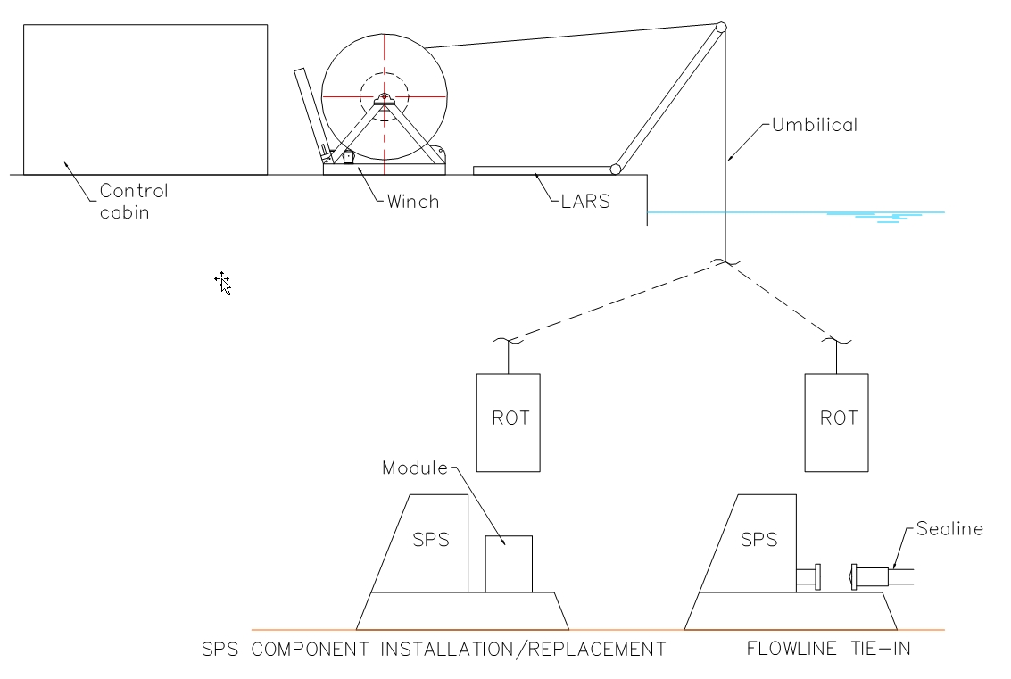
Remotely Operated Tools (ROT) are generally used to perform (a) the replacement or installation of SPS components and (b) flowlines and umbilicals connection (see [36]). They are preferred to free-flying ROV intervention mode when high lifting or pulling capacities are required.
ROTs are lowered by means of lift wires (heave compensation is mandatory) and powered by a surface umbilical with either dedicated thrusters or ROV assistance for lateral guidance. If necessary, the ROV is used to activate backup functions.
As an ROT example used at GIRASSOL field, MATIS (Modular Advanced Tie-In System) is designed to make-up standard ANSI, Taperlok, and API flanges remotely. In several configurations, the system can perform tasks such as lay down head removal, manifold-to-spool piece tie-in, flowline tree connections, and vertical connections to risers.
2.5 Launching and recovery conditions
The remote subsea vehicle is generally launched over-the-side method (sometimes from a dedicated moonpool) for ROVs and from support vessel stern for AUVs and requires a purpose built planned and emergency Launch & Recovery System (LARS) to control the pendulum movements on deck and until it extends through the sea splash-zone.
Because it extends the weather window and provides longer duration dives, the LARS is regarded by many as a major issue in deepwater ROV development, with the umbilical being the most critical item for further improvement.
Such handling system shall be designed, built and operated to suit the conditions in which it is to perform. Today most LARS are equipped with active heave compensation system and designed to meet with sea state 6 vehicle recovery conditions:
significant wave height Hs=4.5m
wave peak period Tp=8s
This implies that ROV operations should not be subject to weather downtime in milder areas (versus North Sea) such as West of Africa, Brazil or Gulf of Mexico (excluding hurricane period), and providing that such diving operations are performed from a suitable surface support vessel.
Working effectively in deep water demands more efficient subsea operations which start with the intervention equipment capabilities, but also includes the ROV personnel / skill and the ROV Subsea Contractor attitude for services and performance.
Efficiency of the crew is a major factor for subsea operation success. Deepwater ROV/AUV workforce is responsible for:
The personnel should be qualified and sufficiently experienced.
For most the deepwater drilling campaign, an ROV crew composed of 3 men (i.e. a superintendent, a supervisor and a pilot) is generally sufficient. However 3 pilot/technicians in addition will be required for continuous 24 hours coverage during the high activity periods such as re-entries or well completions.
Deepwater ROV crew typically consists of the following personnel for "medium" activities (e.g. pipelay), based on 24 hours operations and 12 hour shifts:
One ROV superintendent to assume overall responsibility and to interface with the offshore construction manager.
Two ROV supervisors (one per shift) whose role is to prepare the operations
Two senior pilots (one per shift)
Six technicians (three per shift) to assist senior pilot by manipulating the arm, the TMS, the LARS, etc.
Deepwater AUV crew typically consists of the following personnel for "medium" activities (e.g. pipe inspection).
One AUV party chief to assume overall responsibility and to interface with client offshore.
Electronics engineer for checks and repairs
One surveyor for checking data before transfer onshore for processing.
For subsea construction activities (e.g. flowline tie-ins) a much higher workload will be required from the WROV spreads, in general a minimum of 2 WOROVs and 21 men crew (i.e. 10 men crew/12 hrs shift) are needed.
2.7 Operation documentation
Two media are used to consign and record all the activities:
The ROV documentation should include as a minimum: the as-built or as-installed procedures, the dive log and a summary video version of the operation. AUV documentation is dependent upon tasking. A Large range of sensors are used and recorded on AUV for monitoring activities (MBES, Imaging LASER, FLS …).


