
5 AUV review
5.1 General
The AUV is a vehicle that is linked to its launch & support vessel, only by acoustic means. Such data exchange link being of ‘low rate’ by its nature, the AUV must be managed by on-board autonomous systems. The AUV technology has been recently and mainly developed for the purpose of survey tasks.
5.2 Survey AUVs
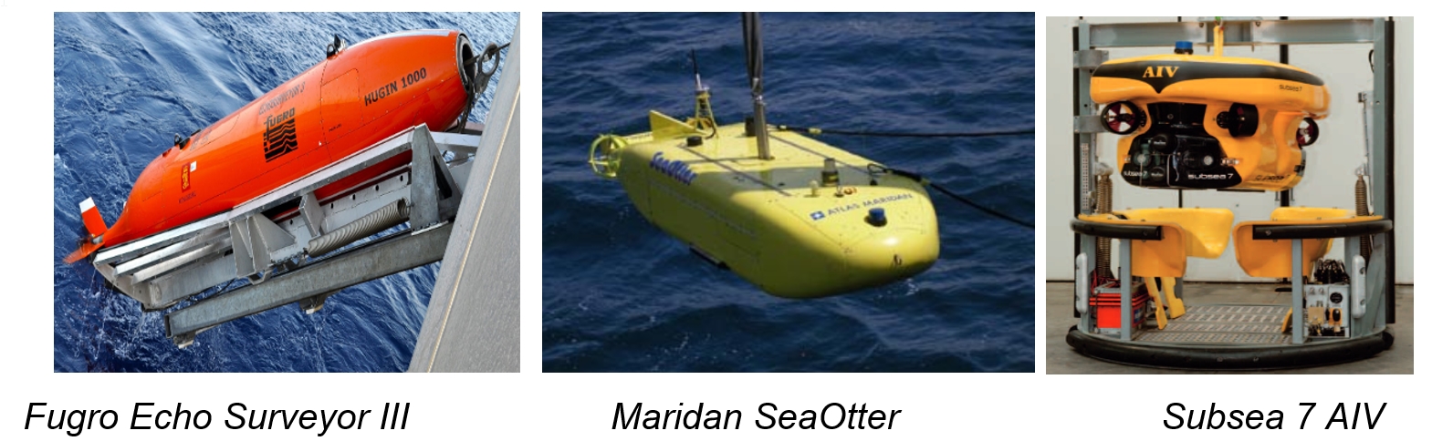
In recent years, AUVs have played an increasing role in data acquisition within the survey market. AUV Inspection Operations starts to be commun in TOTAL E&P. In West Africa for Instance some AUV Inspection Campaigns has been performed in 2014 (TEP Angola), 2015 (TBC in TEP Congo) A new one is scheduled for June 2019. As autonomous and un-tethered vehicles, they are capable of travelling a pre-defined route gathering detailed seafloor, shallow sub-bottom profile or as-laid pipeline information. This is done with the help of surface vessel positioning support as AUV autonomous management is over-estimated.
The AUV technology is an alternative in the geophysical or pipeline survey data acquisition domain to the following technologies:
The selection would depend on the specific task, but the main advantages of the AUV are related to its ability to follow pre-determined route with a surface vessel during the task performance. The AUV can hence be fitted with high resolution survey tool and in the same time cover a large surface area to obtain very accurate data. The AUV is characterised, with regard to the towed vehicles, by a high manoeuvrability (e.g. Hugin AUV is capable of 15m turn radius, completing turns in seconds compared to the typical 1.5-2.5 hours for towed fish) which allow covering closely spaced survey lines for detailed mapping results.
The AUV typical positioning system is composed of the following items
Inertial Navigation System (INS). It is a dead-reckoning system (i.e. that continually updates the position of the vehicle by adding its movements) based on three accelerometers and three co-planar rate gyros.INS requires an accurate determination of start position. However, over time, the navigation system is subject to drift. It is generally corrected by feeding external references at intervals along the route (see following equipment).
Doppler Velocity Log: This sensor allows a bottom tracking and gives the velocity of the vehicle versus the sea bottom. Velocity combined with initial position, heading and INS inputs allow for a better position estimation using algorithm such as Kalman filters.
Altimeter: Used to calculate position ( z axis)
Ultra-Short Baseline (USBL) or Long Baseline (LBL) systems. These systems allow position fixes which are used for a better AUV positioning although accuracy of USBL, in Deepwater, imposes a significant deviation.
The USBL is the industry 'standard' system for position measuring and comprises a single transceiver unit mounted on the hull of the support vessel and a transponder on the vehicle. Position is calculated by measuring the time taken from sending a transponder interrogation signal to receiving its reply in the different elements of the transceiver. In order to calculate sound travel distance AUV/USBL water column sound celerity is measured with a Sound Velocity Profiler (SVP). This measure need to be updated (daily) as celerity varies with salinity and temperature.
In deep-waters, the system is often combined with a Doppler Velocity Log (DVL) to improve accuracy.
The LBL is a more accurate positioning system, which consists in a series of transponders on the seabed to be interrogated by the vehicle.
The AUVs used for surveying a pipeline (as-laid or through life pipe configuration survey, e.g. for lateral buckle monitoring) shall also be equipped with an Autotracker system, which allows the AUV to determine the accurate position of a pipeline and to follow it based on image tracking and pattern recognition techniques.
Survey AUVs are typically fitted with the following monitoring equipment:
Swath bathymetric system (multibeam echo sounder), to give detailed water depth and seafloor topography. This acoustic technique uses a beam radiated downward in a plane perpendicular to the line of travel of the transponder, the echo strength depends on the reflectivity and the orientation of the target.
Side scan sonar, to show seafloor features. This acoustic technique uses a beam radiated laterally in a plane perpendicular to the line of travel of the transponder.
Chirp sonar sub-bottom profiler, to provide statigraphic and geologic detail to penetrations of up to about 60m below mud-line.
Magnetometer: Measures magnetic field variation (applicability in pipe tracking).
Laser Bathy System: Laser Swath with higher resolution than acoustic solution but range limited typically 10m (depends on turbidity).
Still images and rarely video


