4 Deepwater ROV review
4.1 General
Deepwater ROV systems are composed of the following main items:
Additional equipment and tools are then added, depending on the subsea tasks to be performed and the ROV intervention mode (e.g. with TDU, tool skid, etc.).
Most of the ROVs are fed with hydraulic (and electric) power (e.g Millenium plus 220HP). Some ROVs feature up to 270 hp (e.g. Maxximum®, Oceaneering ). As per TOTAL rules GS-EP-SPS-027 Ref.[11] for subsea construction 150 HP are required.
A new generation of all-electric ROVs is emerging (e.g. Seaeye Marine Panther Plus light work ROV, or the Schilling Robotics Quest WROV), with the advantage of a reduced umbilical diameter and weight (a critical parameter for deepwater operations). They typically feature a power of up to 135kW, i.e. equivalent to 180hp system (e.g. eNovus, Oceaneering Work ROV).
ROVs are now typically rated for water depth of 3000m. This water depth can even be further extended as already demonstrated on some untypical projects such as the intervention on the Prestige wreck (3800m water depth, in 2003), whereby the Sonsub's 150HP work class Innovator which was up-graded for that purpose.
The deepwater operations performed on the Prestige wreck were made possible by upgrading the following components of the 'standard' 3000m version of the ROV:
Buoyancy modules, to support the hydrostatic pressure corresponding to the 3800m water depth and which are made of 50mm diameter epoxy composite spheres within an epoxy/glass matrix.
The (Schilling) manipulators (which are now 4000m rated on a standard basis)
Longer umbilical and tether (i.e. 1100m instead of the standard 200m tether length) were fitted on the system, in order to be able to reach the very deep waters of the site and to increase the horizontal displacement envelop of the ROV.
Umbilical and tether winches, on which grooves were added for better and safer handling of the long umbilical and tether, in particular during recovery.
The following sections further describe the ROV vehicle, control system, LARS and TMS as common parts of all the (deepwater) ROV systems. The different types of deepwater ROVs are then depicted.
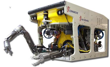
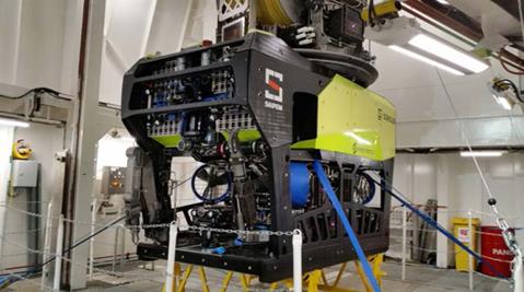
4.2 ROV vehicle system
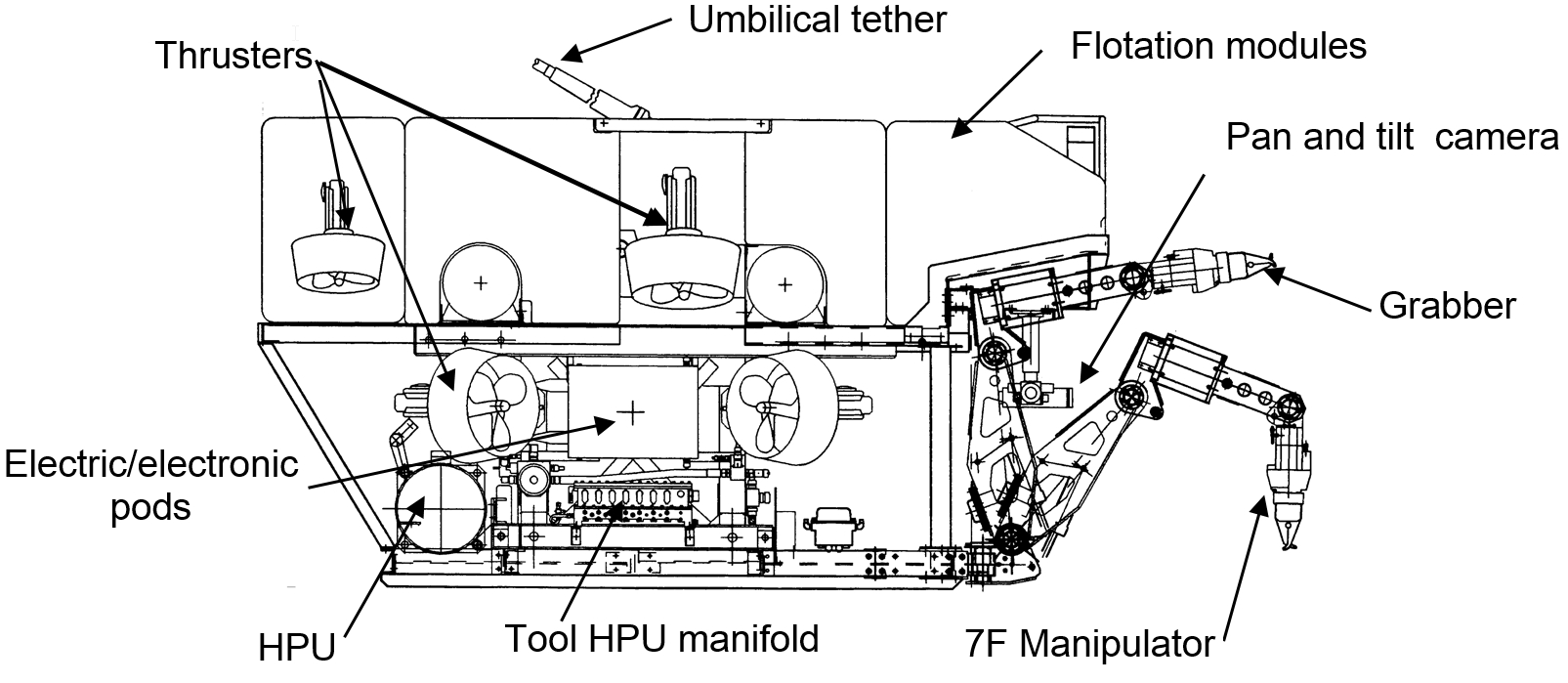
The ROV vehicle is composed of an open frame, fitted with buoyancy modules, supporting the hereunder detailed minimum equipment and possibly some additional tooling (e.g. TDU, services skid, etc.):
FPU and propulsion system
observation equipment
navigation aid equipment
cabling system
manipulator arms
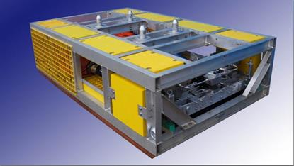
4.2.1 Vehicle structure
The ROV vehicle structure is a welded open frame, made generally from aluminium alloy with stainless steel fixtures and designed to:
The open configuration keeps clear waterways for thrusters water flows. The frame is protected against corrosion (e.g. sandblasting) and fitted with anodes for corrosion control.
Deepwater ROV vehicles are equipped with syntactic foam flotation modules, which provide adequate trim and allow the ROV to be slightly buoyant.
The syntactic foam is preferred to materials such as polyurethane or copolymer foams due to its deepwater pressure resistance capacity. Syntactic foam is composed of hollow glass microspheres (typical diameter of about 100 – 150 microns) dispersed within a base polymer; hollow macrospheres (typical diameter of 5cm) can be added to reduce the foam density. A 2500m water depth rated composite syntactic foam typically has a density between 450 – 500 kg/m3.
4.2.2 Hydraulic power and propulsion
The ROV vehicle is generally powered by two hydraulic power units (e.g. 2 x 75 hp), each being able, if required, to independently operate the system at reduced power hence providing reliability.
Each FPU is composed of the following main items:
Electrical motor (e.g. 50 hp, three-phases, 60Hz, 2300 VAC motor)
Hydraulic pump
Coupler, joining motor and pump, contained in an oil filled, pressure compensated housing to avoid water ingress
Pressure compensated reservoir, feeding the pump
The hydraulic power is distributed by means of valve manifolds to the various ROV sub-systems, which are mainly:
Thrusters
Manipulators
Camera pan and tilt motors
Tools
ROV is typically equipped with 6 – 8 thrusters allowing manoeuvres in all directions. Thrusters are controlled by servo valves which supply the thruster with hydraulic power. Each thruster is able to provide typically about 250 – 300 kg of thrust.
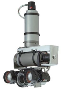
4.2.3 Observation equipment
Camera function is to provide visual support to the ROV pilots in order to manoeuvre the vehicle and perform the various subsea tasks with manipulators.
Different types of cameras are generally fitted on ROV:
SIT (Silicon Intensified Target) low light camera
CCD (Charge Coupled Device) cameraCMOS (complementary metal-oxide-semiconductor ) camera
SIT camera is primarily used by the ROV pilot during the vehicle's manoeuvres. It provides a wide angle of vision and the best viewing in poor visibility conditions, in order to discern the eventual obstacles (e.g. cable or rope). With the low light viewing capabilities of the SIT camera it is possible to locate a target from a further distance than a CCD camera.
CCD camera is generally used for close in work or inspection tasks (It can be for example mounted on a manipulator to view tooling functions). The current trend is to develop the CCD technology to replace the SIT cameras, by combining the technology with high-gain low-noise amplification to provide equivalent low-light performance to the SIT in underwater operations. Depending on the choice of intensifier, the intensified CCD camera is from 100 to 500 times more sensitive than the SIT technology. In addition, the CCD camera is highly resistant to shock and vibration, as well as being smaller in size and weight and consumes less power.
CMOS sensors cameras has a consumption lower than CDD and have and are todays the default choice for ROV cameras. Tether Management System (TMS) generally are fitted with CCD cameras.
Different definitions are available for ROV cameras:
Standard Definition (SD)
High Definition (HD)
3D HD (optional)
4K UHD (optional
The cameras can be located:
With a camera positioned at the rear of the vehicle it is possible not only to perform manoeuvres but also to check the tether umbilical positions. A further camera can also be fitted on the TMS to allow viewing of the tether winch (umbilical entanglement), various gauges located on TMS (e.g. hydraulic gauges of FPU, which provides power to the tether drum) and the whole vehicle deployment and recovery process.
A sufficient lighting system must be fitted on the ROV to provide the required video coverage. About four to five 250 Watt lights (e.g. dry quartz halogen or led lamp) are typically mounted on the ROV vehicle, on the pan and tilt unit, at the front and rear of the ROV to provide the uniform, balanced lighting required for video coverage.
3D Stereoscopic photogrammetry start to be used in survey industry. This technology allows visualisation of 3D points cloud images (useful for comparison with original 3D model) and also allow a precise relative positioning versus a known structure.
4.2.4 Navigation aid equipment
The ROV must be equipped with heading, depth, altitude, and pitch and roll sensors to assist the pilot during manoeuvres.
The gyrocompass heading sensor provides the pilot navigational aid to assist in tasks requiring directional orientation (e.g. locating the work site). A depth sensor or altimeter can be used to hold vehicle position in the mid-water column while performing an operation, but the altimeter is generally more accurate and stable due to a shorter range (i.e. typically 50m). Inclinometers help the pilot or the autopilot functions in controlling the vehicle position, roll, pitch. Roll sensors are particularly useful when docking or mating operations are performed or to work above a slope bottom.
Navigation sensor such as Doppler velocity log can be integrated as navigation aid in order to improve ROV positioning and provide ROV velocity vs sea bottom.
Use of sonar allows spatial orientation and easy location of targets (e.g. SPS, pipelay) during operation. Generally, as the ROV operates in a predetermined area, a medium to short range sonar is sufficient, allowing to track target in relatively close range (i.e. up to 100 - 200m) and to obtain high resolution images.
The current trend in navigation aid is the development of live 3D visualisation of the worksite. In recent years, the 3D visualisation software and hardware technologies have become mature and will allow various applications in the remote subsea intervention domain throughout the project:
Development of installation procedures, particularly for complex operations or accessibility checks.
Training of project personnel, and in particular of ROV crew
Risk identification
Live visual presentation of the intervention environment during operations.
The live 3D visualisation during ROV operations would be of high interest particularly in low visibility conditions among complex subsea structures by providing an enhanced navigation display for the operators. It uses a virtual model of the subsea environment (e.g. 3D model of the field as-installed subsea structures) and real time data inputs (e.g. from the ROV sonar, cameras…) to position the vehicle within its environment and create a 3D live visualisation of the subsea worksite.
This technology has not yet been used for ROV operations, but it is already implemented to monitor the catenary of a pipeline during installation and laydown. For instance the Technip's Pipe Lay Support system is used on the Deep Blue pipe-lay vessel, providing information on the catenary shape and touchdown point.
4.2.5 Cabling systems
Connectors are generally used on external components to facilitate control and maintenance. All the connectors are pressure balanced to avoid water ingress by means of oil-filled, pressure compensated tubing. A junction box is used to centralise the main connections and to minimise the risk of leaking and ease the maintenance.
4.2.6 Manipulator arm
Deepwater ROVs are typically equipped with either one seven-function manipulator arm and one five-function grabber, or two seven-function manipulator arms (i.e. construction tasks).
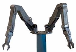
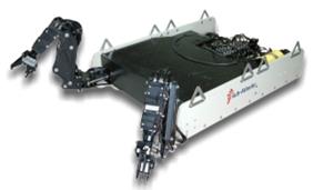
4.2.6.1 Manipulator arms
The manipulator's joint movement is provided by a combination of hydraulic ( or electrical) cylinders and rotary actuators. The state of art is a 'six degrees of freedom' plus claw, master / slave system for underwater applications.
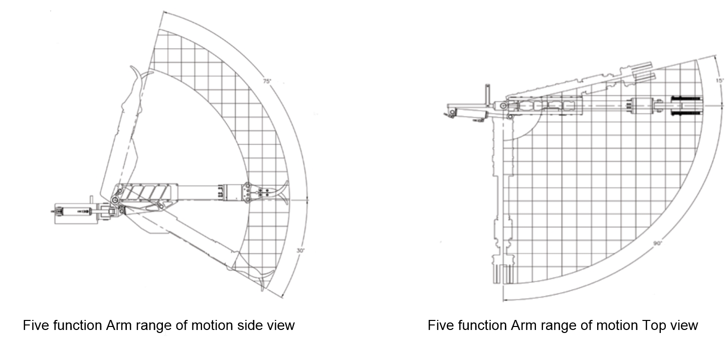
The typical characteristics of five-function and seven-function manipulators are hereafter described:
Five-function arm/grabber typical characteristics:
Linear working area: 1 – 1.5m
Lifting force fully extended: 180 kg (270 kg retracted)
Rotation torque at the wrist: 150Nm
Wrist rotation: 360°
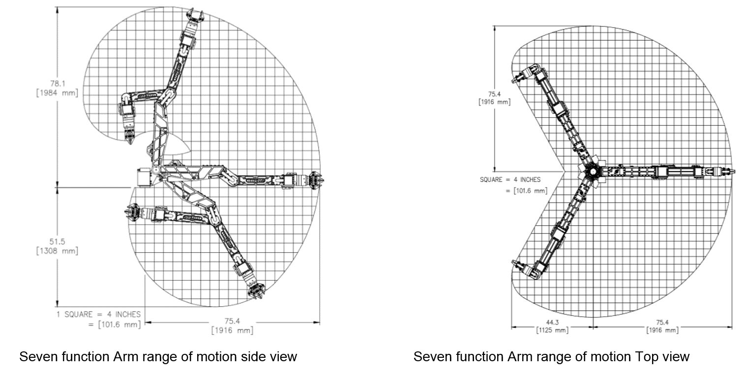
Seven-function manipulator arm typical characteristics:
Nominal depth rating: 3000m (can be extended to 6500m)
Linear working area: 1.3 – 2m
Lifting force fully extended: 160 kg
Maximum lift: 270 kg
Rotation torque at the wrist: 150Nm
Wrist rotation: continuous 360°
The manipulator arms may be fitted with miniature cameras.
Digital control systems are available, consisting of servo valves and resolvers. The user operates a miniature master arm mounted on a LCD console. The system provides operational options and diagnostic information.
4.3 Control system
The control system is housed in a control cabin located on the surface support vessel deck. A maintenance cabin is also part of the on-deck ROV system, providing an enclosed atmosphere to store spares and perform maintenance operations. Both cabins can be air conditioned, pressurised as Zone 2 and A.60 fire rated if required (e.g. on drilling rigs).
The control system typically comprises:
Pilot's console, with all joysticks, switches, trackball and computer graphics user-interface components.
Navigator's console, including video recorders, a sonar processor and monitors.
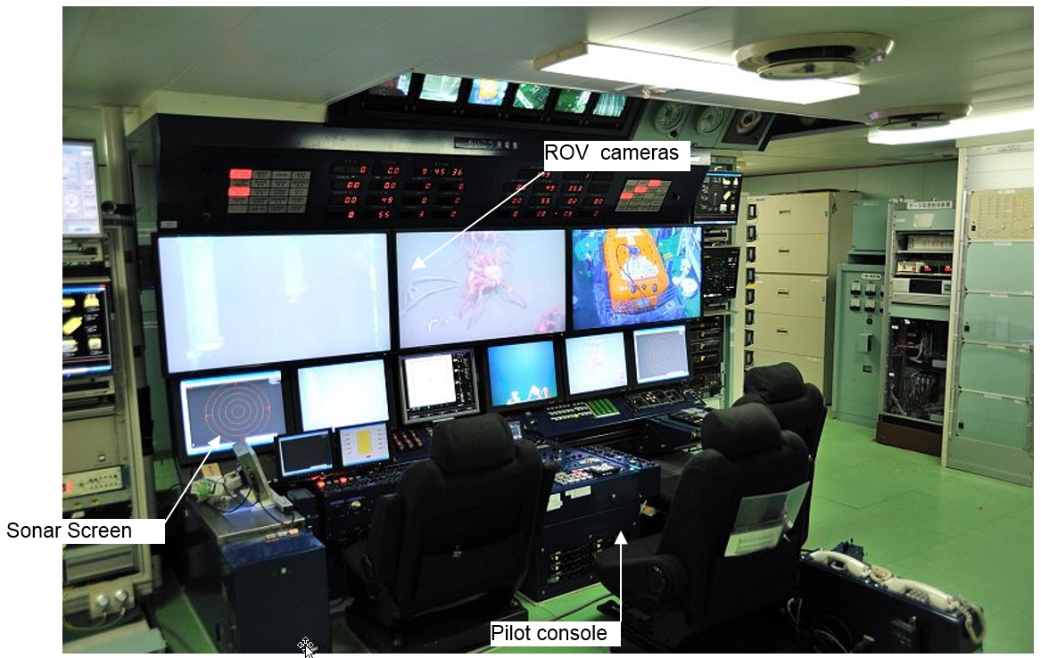
A video overlay on the pilot's monitor allows displaying one or a combination of the following data: date / time, depth / depth history, heading and auto heading set point, altitude, pitch and roll, hydraulic data (i.e. pressure, temperature, and fluid level), motor current and voltage status, thruster’s status, alarms, etc.
Direct communication and telephone links between the ROV control cabin and the "DP" control room must be provided to allow proper subsea intervention co-ordination.
The electrical power distribution is generally enclosed in the control cabin (but separated from the control room by wall for safety reasons), providing power to the ROV system FPU motors, electronic hardware on the ROV and the control and maintenance cabins.
The telemetry and control system is the ‘heart’ of the ROV technology, it provides high speed serial communications, utilising topside computer, and a ‘bottom’ side microchip (e.g. Intel Pentium) control system in the ROV vehicle/cage.
Through the use of standard industrial computer components and ‘custom’ designed software, the control system is flexible, reliable and easily maintained. The control logic for various vehicle functions and any added specialized tooling can be updated or reprogrammed to suit subsea tasks specific needs and applications.
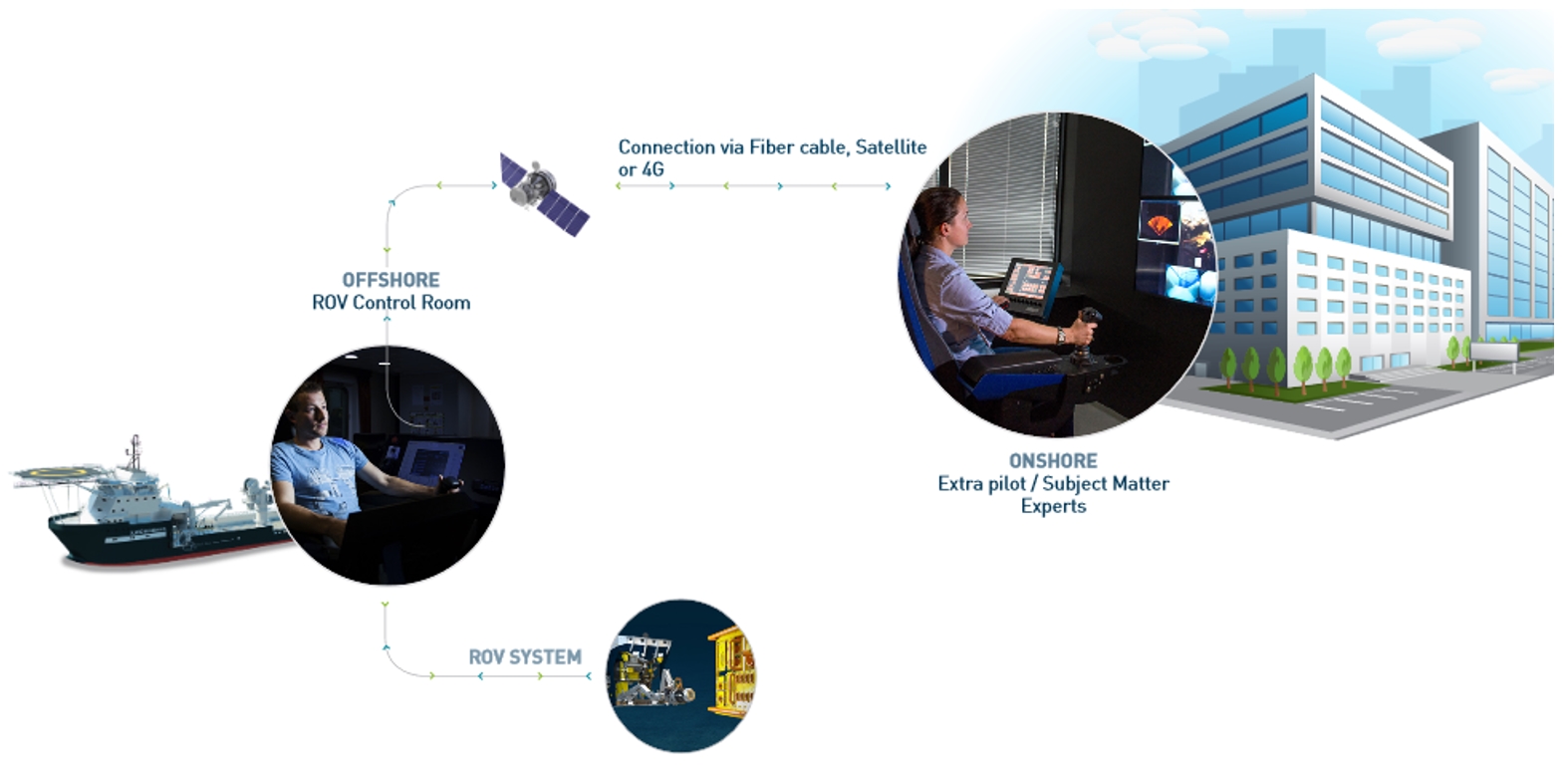
Remote piloting and Automated Control Technology:
This technology as per early 2019 is considered as a future development and is not yet within the O&G industry.
Some Companies the opportunity of full ROV remote piloting via virtual connection technologies such as vessel to vessel radio frequency (RF), satellite/Internet, or subsea optical link. Moreover video processing software analyse video, allow shapes recognition and spatial distance determination for appropriate movement of the ROV.
Increases efficiency using a remote operations base
Provides access to subject matter experts and specialists
Reduces mobilization costs and carbon footprint
Tool Instructed path control enables acquisition, deployment, operation and docking of tooling is also a feature to ease and quicken pilot manipulator tasks.
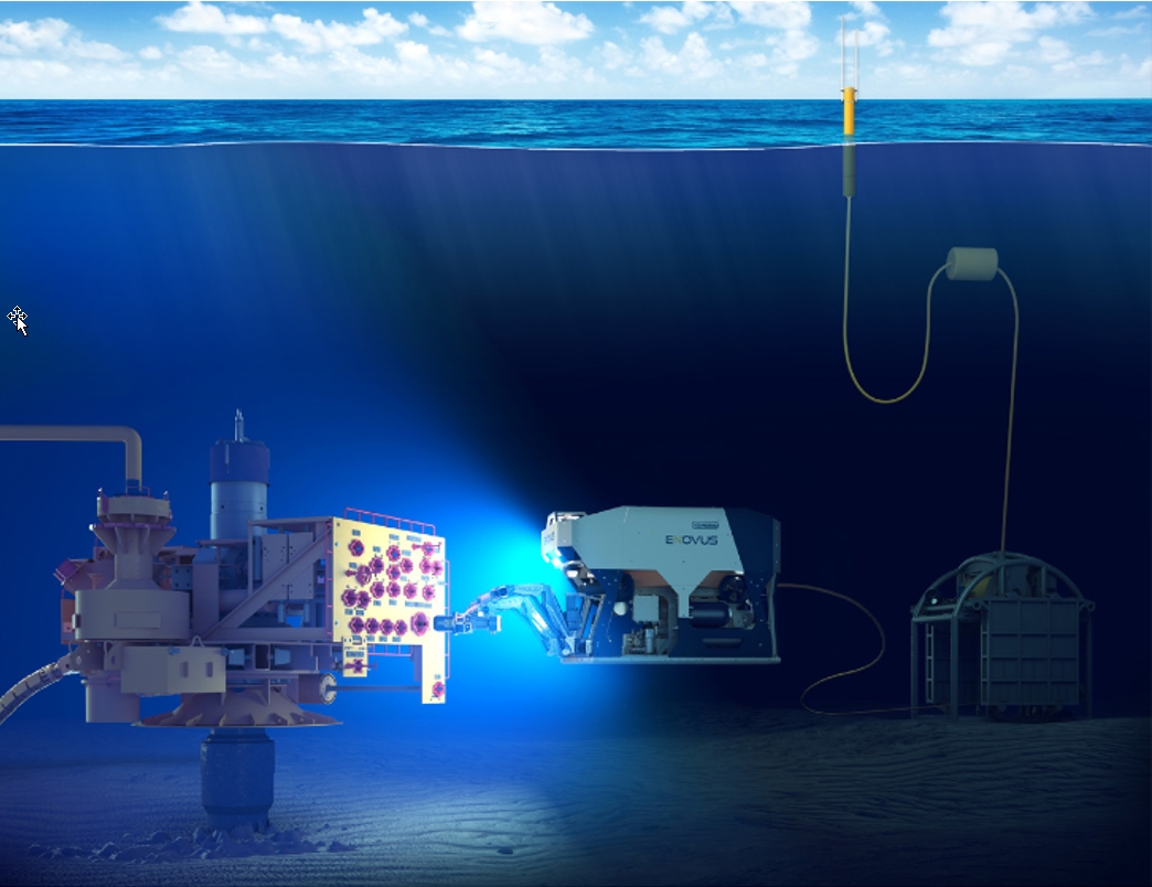
Battery-powered remotely operated vehicle (E-ROV)
This technological solution offers a resident ROV solution and enables operator to intervene faster, keep production online more effectively, and perform routine tasks with fewer deployments.
The E-ROV system is capable of performing common ROV tasks including inspection, valve operation, torque tool operation, and manipulator-related activities. This system is connected to Oceaneering onshore Mission support Center via a 4G/Satellite mobile broadband signal transmitted from a buoy on the water’s surface. This allows a full real time control of the ROV and its tooling.
Removes need for surface vessel
Remotely piloted
Increase operational efficiency while reducing cost
Main parts of this system is the ROV itself (eNovus ROV, compact work class) a subsea garage (Battery pack and tether management system rechargeable from surface), and moored surface buoy (hosts antenna mast for encrypted communications)
4.4 Launching and Recovery System (LARS)
The functions of a LARS are (1) to perform the over-boarding of the ROV and its TMS from support vessel deck, (2) to avoid any critical pendulum motions which would lead to detrimental clashes between ROV and vessel hull and (3) to lowered and recovered the vehicle / TMS assembly through the sea splash zones.
The launching and recovery system consists of following major components:
Handling frame
Umbilical winch
Hydraulic power unit (FPU)
Active heave compensation system
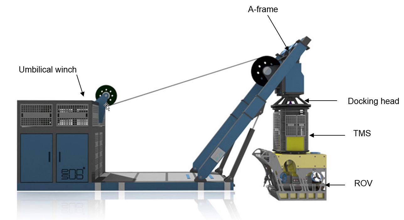
The handling frame can be based on either an A-frame (see Figure 4.12, “A-frame type, based LARS”) or a crane (knuckle-boom or telescopic boom, see Figure 4.13, “Knuckle-boom type LARS”). Its primary function is to perform the over-boarding of the TMS, which is hanged on the docking head and supports the ROV, and to position both TMS and ROV at the sea water level as far as possible from the floater hull (i.e. typically 5m outreach). This is in order to avoid contact due to environmental loads and pendulum movements. The handling frame should withstand the weight of the TMS, the ROV, plus its maximum payload (corresponding to an eventual added tool package); it shall be able to perform its task in severe conditions.
The umbilical winch must be fitted with active heave compensation, thus ensuring safer and simpler docking of the ROV in rough weather conditions. The umbilical winch determines the deployment / recovery speed of the ROV, which is typically about 30m/min. The speed is an important characteristic of a LARS for deepwater applications as launching and recovery times increase with depth, which can result in increased operational costs.
For deepwater and ultra-deepwater operations, the umbilical winch should provide at least a speed of 50m/min.
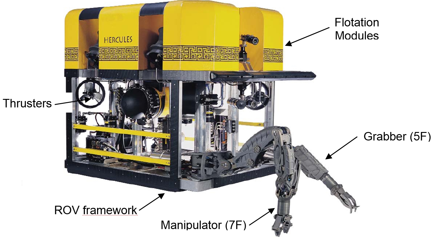
Mobil, who was particularly concerned with this problem in the West of Shetlands on the drilling semi-submersible "Jack Bates", awarded Subsea 7 the design and fabrication of a ROV system.
Subsea 7 developed the "Clansman" ROV system (Figure 4.11, which has now evolved to the Hercules ROV), including not only a deepwater ROV but also a heavy weather LARS. The Clansman LARS is based on the use of four guide wires and a cursor frame which guide the ROV cage from the main deck to the port submerged pontoon level. It allows launching and recovery of the ROV in sea state 8 (i.e. significant waves of up to 10m) and its high speed umbilical winch is able to lower the ROV at a maximum speed of about 140m/min. Such guided systems are now used by several ROV operators, Figure 4.12.
The umbilical is usually the weak element of a ROV system, particularly for deepwater applications due to the umbilical increasing length and weight. The main lift umbilical experiences maximum dynamic (snatch) loads during launching and recovery of the ROV, with the TMS and vehicle freely suspended in water. A failure of a winch or an umbilical statistically results in the longest ROV system downtime period. Efforts are made by ROV/umbilical manufacturers to:
Minimise the weight of the umbilical while maximising its capability
Standardise umbilical design in order to facilitate the stocking of spare umbilical
Deepwater main lift umbilical are typically composed of power conductors and fibre optics internally installed in a helical arrangement to reduce component tension loads (fibre optics can also be surrounded by a protective gel to minimise friction with other components). The umbilical allows the transmission of power, data, telemetry and video between the TMS and the surface. The use of fibre optics can improve the umbilical size and weight; this allows to reduce the drag loads (i.e. the current induces offset) and to minimise the size (and the cost) of the LARS.
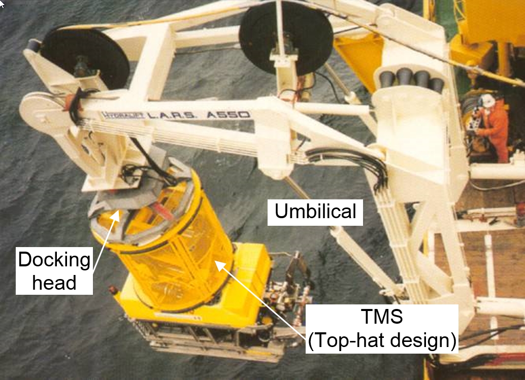
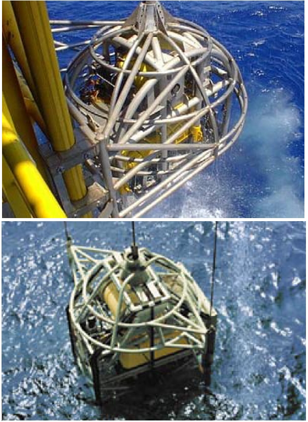
4.5 Tether Management System (TMS)
In general ROV's operating deeper than 300 m need a tether management system to remove the effect of current on the umbilical.
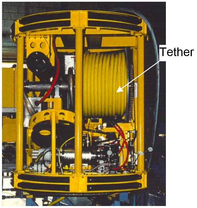
The TMS functions are (1) to latch the ROV during the launching and recovery phases and (2) to manage the tether length while the vehicle performs the subsea tasks. The ROV is unlatched from the TMS and exits when reaching the desired water depth and then can manoeuvre in any direction up to the working length of the tether. The tether umbilical length for deepwater application is typically of around 120m-200m.
The TMS allows decoupling of the vessel motions, surface effects and drag loads on the umbilical through the water column; ROV power can hence be fully used to perform the subsea tasks as the vehicle pulling charge is minimised (the ROV is only retained by the tether drags, which are quite inferior to those acting on the total umbilical length).
Current loads acting on the main lift umbilical and the TMS tend to push it far away from the working area. The TMS weight, this is particularly true when high current are expected, is useful to adequately position the ROV. Some TMS (e.g. the cage of the Hydra Magnum ROV) are equipped with thrusters to assist with positioning.
The TMS is equipped with a FPU (i.e. motor, coupler, hydraulic pump, plumbing, etc.), generally similar to the ROV equipment (spare part stock limitation) and valves to provide with hydraulic power and to control the tether winch (and the eventual TMS propulsion system). Cameras and lights are also fitted for viewing of hydraulic gauges, tether winch and the vehicle deployment and recovery process.
All power and control for the ROV vehicle, after passing through the main lift umbilical, are provided by the tether umbilical.
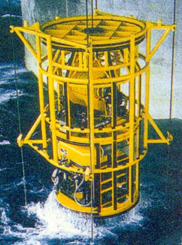
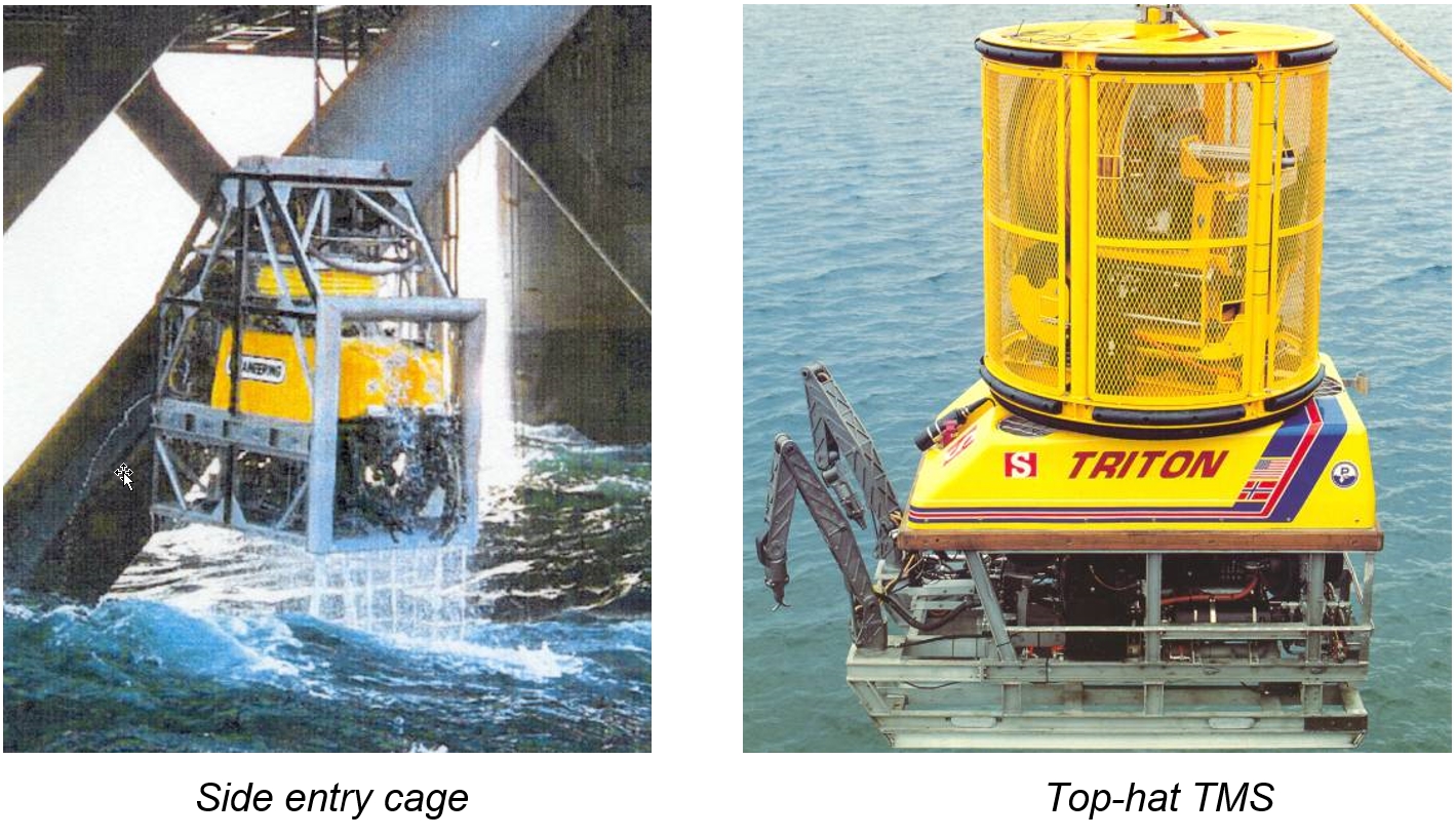
Two types of TMS are available on the market:
Side entry cage
Top-hat TMS
The typical main characteristics of both systems for deepwater applications are as follows:
Side entry cage | "Top-hat" TMS |
|
|
Both cage and top-hat systems are equally used by the subsea contractors as each of the two systems has the ‘reversed’ advantages and drawbacks.
The two main problems encountered with a "top-hat" designed TMS are:
Due to the top position of the TMS and the low submerged weight of the ROV, a turning moment is applied on the ROV-TMS combination when lowered into the water (i.e. the centre of gravity rises above the centre of buoyancy), thus applying large lateral loads on the umbilical termination.
It is relatively easy to pinch the tether when the ROV docks the TMS.
A side entry cage has the inherent advantage of providing protection to the ROV during launching and recovery (useful in bad weather conditions to avoid direct clashes on the vessel hull), but its main drawback is to be less versatile: the size of tools and work packages to be added on the ROV is limited by the cage dimensions.
4.6 Observation ROV
Observation ROVs (OBSROVs) are rarely used during deepwater operations (with the exception of drilling operations): because of its limit working capability (payload, manipulator) heavier ROV are often preferred as they are able to immediately perform more demanding subsea tasks. Nevertheless, class II observation ROV function in deep waters is mainly to perform inspection of the subsea equipment (i.e. SPS, risers, sealines), video monitoring (during tool manoeuvre and positioning) and light subsea works.
Observation ROV can carry a wide array of light sensors and probes, plus a simple (i.e. up to five-function arm) grabber, but it cannot carry heavy loads.
As an example small Observation ROV as the Falcon which is commonly used for FPSO inspection and eyeball ROV are commonly used for FPSO tanks inspection.
The main characteristics of a typical deepwater class II observation ROV are as follows:
The enclosed Annex 1 provides further technical characteristics of the main class II OBSROV for deepwater applications.
4.7 Drilling ROV
The drilling ROV will generally provide the required assistance during:
Drilling, re-entry and well completion
X-mas tree installation
Blow out prevention assistance with the High Flow Pump Skid
In particular, it must be suitable for performance of typical subsea tasks as follows:
General observation
Observing well spudding
Watching for fluid and cement returns to seabed
Observing and advising rig about guidance of bit or casing into well
Observing landing of equipment (e.g. guide base, BOP) at seabed
Observing and reporting currents
Quality control observations
Checking bulls-eye for inclination of guide base, BOP, etc. (+/-1deg)
Checking orientation of guide base (+/-5deg)
Checking elevation of conductor above seabed (+/-0.5m)
Checking position of subsea equipment relative to rig position (+/-0.5m)
Confirming position of connector latch indicators (+/-1cm)
Observation of wellhead seal surface (from distance of about 0.25m)
Observing pressure during function tests with ROV stabs (+/-0.5bar)
Observation of BOP alignment pin position (+/-1cm)
Manipulation tasks
Position beacons on seabed and/or on subsea equipment
Insert hydraulic stab onto BOP, tree, tubing spool and pressurise (e.g. 210bar) to function/pressure test with sea water
Install and remove environmental gasket onto/from wellhead
Actuate retaining rods on BOP connector to release
Cut hydraulic line
Clean (mechanical and hydraulic jets) external and internal wellhead housing (seal surface)
Manipulation of needle valves on BOP control panel
Connect/disconnect lift wires to/from subsea equipment
Remove small debris
Remove/clean cement and cuttings from guide base
Operate manual (ROV) gate valves
Override hydraulically actuated tree valves
Carry and install tree cap
Pressure control and methanol injection in tree cap
Connect/disconnect electrical subsea connections
Drilling ROVs are class III deepwater ROV. The main characteristics of a typical deepwater drilling support ROV are as follows:
Dimensions: 2.5m x 1.5m x 1.6m (LxWxH)
Total power: 100hp
Weight in air: 1.6 tonne
Depth rating: 3000m
Speed: 3 knots forward
2 knots lateral
2 knots vertical
Payload: 220kg
Manipulator: 1 off 7 function + 1 off 5 function manipulator arms
The deepwater ROV system as a minimum should be equipped as follows:
Scanning sonar with a range of 200-250m and a 360° angle
Two (2) manipulator arms, at least one 7 functions and one 5 functions
Two (2) video cameras with at least one (1) being high resolution colour camera and both equipped with pan & tilt system and video recorder
Data transmission via fibre optic technology
Following instrumentation shall be connected to a surface display:
Automatic/manual heading and depth control, and be able to lock itself in all three (3) axis by means of its control system
Gyrocompass
Thermometer for water temperatures at seabed
Depth-meter
HPR system
Thruster propulsion system shall be sufficient for propelling and manoeuvring the vehicle in all directions at any depth and withstand currents up to 2 knots at sea-bed level
High pressure pump system, 3000 psi, with line and hot stab for BOP actuation
ROV tools :
AX or VX ring tool
Hydraulic cable cutter
Hydraulic actuated wrench for 2" sockets for instance
The drill support ROV, shall be able to be trimmed neutral buoyant (or slightly positive) when carrying special tools.
The ROV shall be capable of a through frame lift of 500 kg (in air).
The ROV hydraulic power packs shall have spare valves to be able to operate two functions bi-directional at an operating pressure of 210 bar (e.g.).
4.8 Working ROV
Deepwater working ROV (WROV) are used for installations or production supports, to perform subsea tasks such as:
All tasks as for drilling ROV (see Section Section 4.7, “Drilling ROV”), plus
Landing, make-up, test, disconnect the subsea production system
Pull-in and connection of flowlines and umbilicals
Install electrical and hydraulic flying leads between SPS
Hydraulic primary and secondary tool operations
Operation of valves as primary or override functions
Water jetting and dredging
Deploy, install, make-up, test, disconnect, recover the X-mas tree mounted equipment (i.e. choke inserts, control modules, chemical injection, flow meter module)
Operation of other purpose designed ROV tooling
etc.
The deepwater working ROV is a new generation of vehicle specifically designed for construction support activities and equipped with a Tether Management System (TMS).
Working ROVs are class III deepwater ROV. Typical characteristics are as follows (see Annex 1, which gives further technical characteristics of the main class III deepwater ROV in tabular form):
Dimensions: 3m x 1.8m x 1.9m (LxWxH)
Total power: 100hp – 250hp
Weight in air: 3.5 tonnes
Depth rating: 3000m
Speed: 3 knots forward
2 knots lateral
2 knots vertical
Payload: 150kg – 300kg
Through frame lift: 1ton – 5ton
Manipulator: 2 x seven-function manipulator arms
The ROV system shall be capable of operation down to the required depth and as a minimum shall be equipped as follows:
Scanning sonar with a range of 200-250 m and a 360° angle
Two 7 function manipulator arms with the following SPS requirement (see also Section Section 4.2.6, “Manipulator arm”):
1.3m reach
Wrist function of continuous 360° rotation
Claw rotate torque of 75 Nm minimum
Lift capacity of 500 N at full extension and 1000 N in retracted position
Alternatively, computer assisted manipulators (based on latest technology for environment acquisition and load return forces) can be proposed for elementary & repetitive tasks such as valve operations, torque operations, etc,
Two (2) video cameras with at least one (1) being a high resolution colour camera and both equipped with pan & tilt system and video recorder
Data transmission via fibre optic technology
Following instrumentation shall be connected to a surface display:
Automatic/manual heading and depth control and be able to lock itself in all three (3) axis by means of its control system
Gyro-flux gate compass
Thermometer for water temperatures at seabed
Depth-meter
system
Thruster propulsion system shall be sufficient for propelling and manoeuvring the vehicle at any depth with current up to 2 knots at sea-bed level
Multiplexing control capability allowing additional sensors and tools to be attached, with additional spare twisted pair to allow for additional direct control
High pressure pump system, 3000 psi, with line and hot stab for override functions on the SPS
ROV tools :
hydraulic cable cutter
hydraulic actuated wrench for 2" sockets
water jetting & dredging tools
The working ROV, shall be able to be trimmed neutral buoyant (or slightly positive) when carrying special tools or equipment (such as tree-jumper tie-in tools, tool basket, etc). The ROV shall be capable of a through frame lift of 2000 kg (in air).
The ROV hydraulic power pack shall have spare valves to be able to operate two functions bi-directional at an operating pressure of 210 bars.
4.9 Survey ROV
ROV in charge of seabed survey operations must have the following characteristics to efficiently perform its tasks:
High video capacity. Survey ROV must be equipped with several high resolution colour cameras, powerful lighting system and great capacity of data transmission.
Sufficient propulsion capacity to be able to rapidly perform the survey of large areas (e.g. 1 knots during deepwater pipeline inspection).
Typical survey ROV characteristics are as follows:
Propulsion: 100hp (minimum)
Manipulators: 1 x seven-function and 1 x grabber
Sensors: Gyro, DVL, depth sensor, sonar, etc.
Video overlays and recorders
It must also be equipped with a junction box and skid capability allowing to add typical survey instruments such as:
Trench profiler
Bathymetric system
Boom cameras
Cathodic protection detection systems
Pipe tracker
etc.