
7 ROV tools
7.1 General
This chapter aims to describe the main ROV tools (i.e. descriptions and functions). The list is not exhaustive and the description remains general as various tools exist and some of them can be custom-made for special applications.
Additional tools are added, depending on the tasks to be performed by the ROV. Such ROV tools (interface tooling), so far as possible, should be designed to operate with a range of ROVs and not limited in application to one type of ROV.
All the deepwater ROV tools and equipment shall be rated to the adequate water depth.
7.2 Tool handling and implementation
Four main ROV tooling configurations can be adopted to perform subsea tasks:
Manipulator arm is a flexible way to perform subsea tasks, either directly using the manipulator gripper or a manipulator held tool. Deepwater ROV manipulator is typically either five-function arm, which mainly plays the role of grabber, or seven-function arm with high versatility.
Following topics must be addressed for intervention efficiency:
Precision and repeatability of the task to be performed to evaluate the suitability of manipulator.
Weight of any manipulated component, which must be checked with reference to the manipulator handling envelope capacity.
Location of the interfaces with regards to the manipulator working envelope.
Mechanical resistance of tools and interfaces, which must resist the loads applied by the manipulator.
Stabilisation method, allowing complex manipulator arm operation.
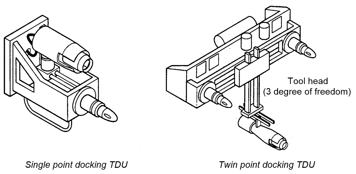
The Tool Deployment Unit (TDU) is a tooling package comprising one or two docking probes and a tool mounted on a ‘cartesian’ carriage arrangement. The TDU is installed at the front (or the rear) of the ROV in addition to or in replacement of the manipulators. The docking point(s) provide stability and accurate positioning while the one-, two- or three-degree of freedom carriage arrangement allows the tool head to access one or several intervention interfaces.
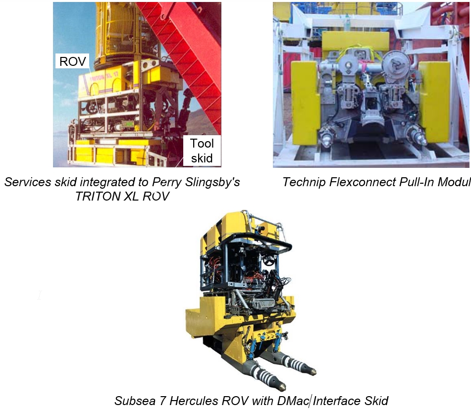
A tool skid can be installed under the ROV vehicle in order to perform:
Either the installation of component (such as control pods and chokes)
Or the installation and connection of flowlines or umbilicals (hydraulic or electric connections).
Tool skid can be either surface connected to the ROV vehicle, involving a dual LARS deployment (ROV through frame lift capability), or integrated at the seabed level (e.g. ROV flying and docking onto the tool skid).
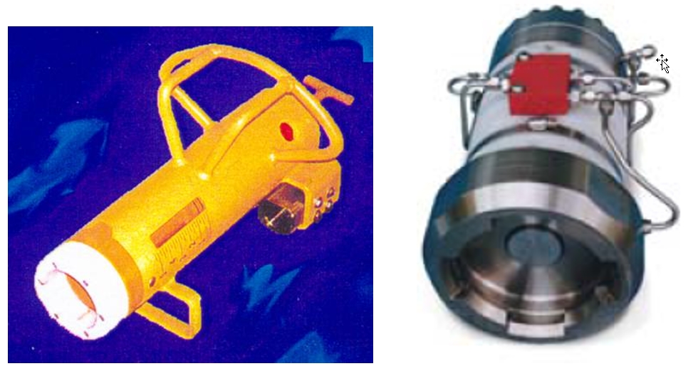
7.3 Hydraulic control intervention tools (hot stabs)
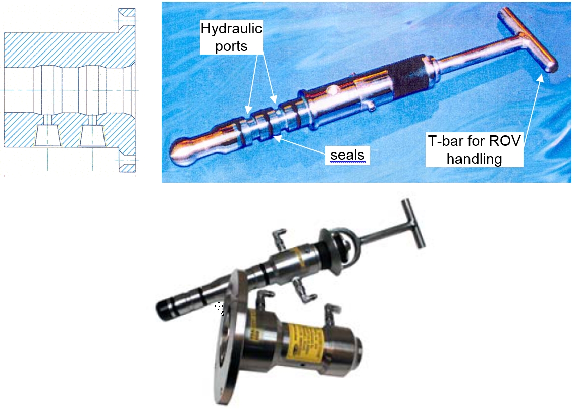
Hydraulic control intervention tools, or hot stabs, are designed to provide remotely actuated subsea functions via the ROV. Hot stabs mainly consist in an insert style male probe, fitted with internal hydraulic gallery and ports, used in combination with a female receptacle mounted on the subsea structure. Single or multi-port versions are available; in the last case each separated section is isolated from the others by seals.
They are typically used for:
Hydraulic activation of valves
Testing of connection sealing
Overriding of existing systems
Hot stabs can be operated by manipulator or TDU.
7.4 Rotary torque tools
Rotary torque tools output a rotary motion generally using a hydraulic motor; all working drive components are positioned within oil compensated housing to avoid water ingress.
Rotary torque tools are used in various ROV applications such as:
Actuating manual gate valves
Tightening screw (e.g. clamp connector)
Overriding or operating subsea tree valves
Completing lockout operations of SCSSV circuits
Operating running tools
Releasing shackles
etc
The rotary interface is standardised by the API RP 17H for low torque and high torque tools:
Low torque (i.e. up to 75Nm) interface on SPS consists of a "T" bar or paddle enclosed in a tubular housing
High torque interface consists in a square drive stem enclosed in a tubular housing
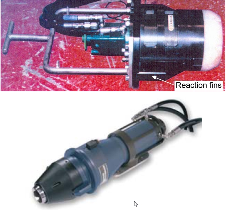
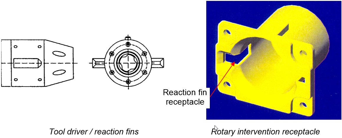
The design principle of the high torque tools involves no transmission of loads to / from the ROV: reaction against the torque produced is provided by a pair of reaction fins mounted on the tool and mating the female receptacle.
Rotary (high) torque tool typical characteristics are as follows:
Length: 650mm
Diameter: 310mm
Weight in air: 50kg
Maximum torque: 2700Nm (typical)
Output speed: 0.7 – 1.9 rpm
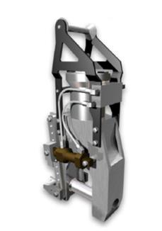
7.5 Linear valve override tools
The functions of this type of tool are to actuate, override and lock open various gate valves requiring a push action.
The reaction against the pushing force produced is internally reacted by tool. The interface consists in a flange surrounding a central stem. The ROV mounted tool is engaged upon the interface and locked onto the flange. Once installed and locked into place, the tool provides a linear ram that is counteracted by the flange interface.
Typical linear valve overriding tool characteristics are
Weight in air: 60kg
Maximum output force: 50 – 70ton
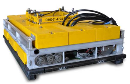
7.6 High Flow Pump skid
High Flow Pump Skids are designed to enable the ROV to quickly close the Blow Out Preventer (BOP) rams and safety valves on SPS equipment. This functionality is compulsory as per TOTAL Rules (CR EP 411) This Fluid Transfer Skid system components are mounted in an aluminum alloy skid, which can be adapted to be compatible with multiple types of ROVs. The output of the fluid skid is accurately measured using electronic flow meters and pressure transducers, allowing the output of the skid to be graphed vs time. In addition to these functions, the skid can also pump through a dual port hot stab to 10,000psi (689bar), with the ability to remotely select which port the high pressure fluid is directed to.
Dimensions | 2830L x1860W x630Hmm |
Weight in Air | 1265kg |
Weight in Seawater | 55kg |
Max. Weight of the ROV | 6000kg |
Useable Volume of Control Fluid | 180-200L |
Max. Output Pressure | 10,000psi (689bar) |
Max. Output Flow | 260L/min |
Nominal High Flow Output | 200L/min @ 3000psi |
Supply Flow | 220L/min & 80L/min |
Fluid Filters | 5 microns |
Depth Rating | 3000msw |
Supply Input Pressure | 3000psi |
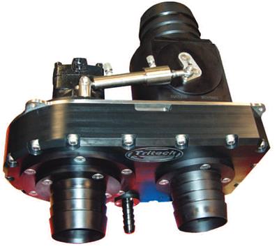
7.7 Dredge / jet pump system
This tool is a ROV mounted hydraulic pump unit for removal of mud located on landing areas for intervention tools, receptacles, etc.
7.8 Hydraulic cable cutter
Hydraulic cable cutter is an hydraulic operated ROV tool for cutting either soft line or hard line wire rope (up to 100mm for the tool below). The cable is trapped by an anvil rod and then cut by a blade. It is generally handled and positioned by means of manipulator.
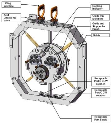
7.9 Flowline hub cleaning tool
The flowline hub cleaning tool is a hydraulic operated ROV tool for cleaning of the flowline hubs. It exists in mono- and multibore hub versions. It is composed of rotating brushes and can include cameras in order to inspect the hub.
This type of tool is used to clean a flowline hub prior to either a connection or a seal replacement operation.
Typical characteristics of 9" flowline hub cleaning tool are:
Dimensions: 0.1m x 0.5m x 0.9m (LxWxH)
Weight in air: 30kg
Weight in water: 20kg
Hub Cleaning Tool: Two of the stabs provide hydraulic power for CCW and CW rotation and one stab provide citric acid. Hydraulic supply is provided through a stab jumper from the ROV.
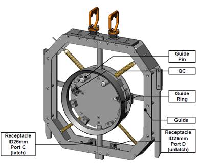
7.10 Seal replacement tools
This is a ROV back-up tool used to replace the sealplate and/or the gasket inside the flowline connectors with a new sealplate if this should be required.
Seal replacement tools are generally designed to be used in combination with a flowline cleaning tool.
A seal replacement operation basically consists in:
Deploying the ROV fitted with the seal replacement tool (SRT). The deficient connector has been previously opened and stroked back.
Once ROV is docked, the SRT is lowered, by means of a tool elevator, in front of the sealplate.
The SRT grips the sealplate and pulls it.
The ROV, the SRT and the sealplate are recovered. The sealplate is inspected.
In parallel with the inspection of the sealplate, the flowline hub cleaning tool is deployed by ROV and performs the cleaning of the inboard hub, which was containing the sealplate.
The sealplate fitted with new seals is lowered, positioned and re-installed by the SRT.
The connection is then performed and tested.
Seal replacement tool: Typical characteristics of 12" flowline seal replacement tool are as follows:
Dimensions: 0.2m x 0.9m x 1m (LxWxH)
Weight in air: 42kg
Weight in water: 26kg
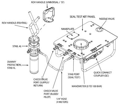
The purpose of the External Seal Test Kit is:
•To verify the integrity of the seal by carrying out a low-pressure test after installation of (for example) an Insert Choke Module or a Multiphase Flow Meter
• To test the seal when a flowline, umbilical, well jumper, or intervention point is connected to hub.
7.11 Hydro-acoustic measurement tool
Accurate measurements are required for some subsea operations such as well rigid (steel) jumper tie-ins (refer to the document "Tie-in methods").
A hydro-acoustic measurement tool consists in four transponders arranged by pairs, which are installed by the ROV on fixed points of the two subsea structures (e.g. W-tree, PLEM) to be connected. Each of the pairs of transponders is mounted on a frame, which fixes them in a known relative position. The ROV handles this framework carrying a pair of transponders and installs it on a predetermined and fixed location on the subsea structure.
Depth sensors are housed in each transponder. Once both pairs are installed (two other transponders can be positioned on the seabed for cross-referencing and increased accuracy), the relative position and orientation of the two subsea structure can be determined by measuring the distances between each transponders and fixing their relative depth.
The accuracy of this technique is typically +/- 5cm (over a 50m length) and 1° on relative headings. The typical characteristics of a hydro-acoustic measurement frame are:
Dimensions: 2.7m x 0.7m x 1.2m (LxWxH) (one pair of transponders)
Weight in air: 90kg (one pair of transponders assembly)
Nominal measurement: 0 – 75m
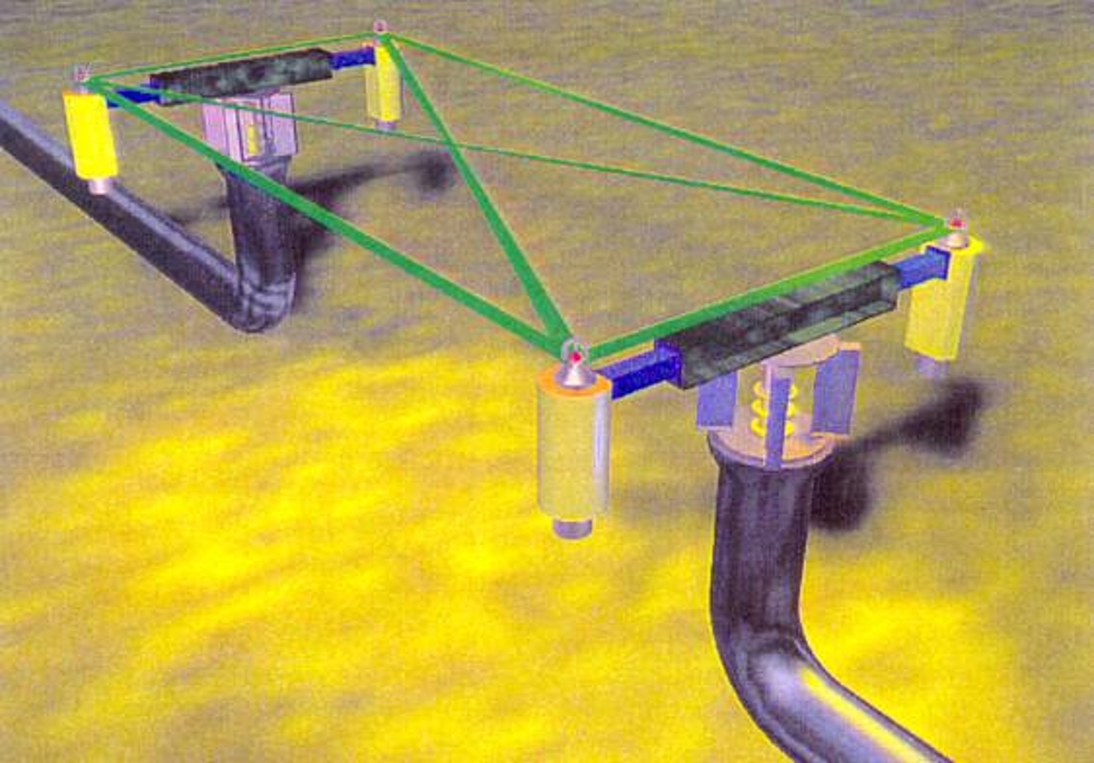
7.12 Taut wire metrology
The taut wire metrology and its applications are fully described in the document "Tie-in methods".

A taut wire measurement tool consists in two assemblies installed by the ROV on the two subsea structures, of which the relative position must be determined.
Each of the two assemblies is fitted with guiding pins to accurately position it on a known location on the subsea structure. Once installed, the ROV deploys a cable between them, which is tensed by a winch part of the main assembly (i.e. containing the cable, the winch, the measuring wheel, etc.).
The measurements are performed using the ROV video to read the various gauges on the tool:
The vertical elevation difference and angular misalignment between the two tie-in points is determined by means of the protractors and dual axis inclinometers. A resolution of 1° can be achieved.
The distance between the two points is determined from the length of the taut line. This length is measured from a calibrated measuring wheel mounted near the winch. This counter can achieve an accuracy of +/-5cm (over a 50m length).
The typical characteristics of a taut wire measurement tool are as follows:
Main assembly dimensions: 0.7m x 0.7m x 1.1m (LxWxH)
Main assembly weight in air: 130kg
Normal measurement: 0 – 50m
7.13 ROV-mounted pull-in and connection tool
Pull-in and connection tools are described in referenced document "Tie-in methods".
ROV-mounted pull-in and connection tools represent the latest generation of tie-in tool. These systems are typically composed of an interface skid which is mounted under the ROV, a pull-in and connection tool which can be deployed independently from the ROV and a tie-in porch which interfaces with the subsea structure. All these tools can be operated by means of a working class ROV deployed from a dedicated ROV support vessel.
The ROV mounted tools have the following general characteristics:
Maximum pull-in force: 30ton
Pull-in distance: from 3m to 40m
Angular alignment: +/-15°
Tool weight: 8-10ton
![]()


