
3 Interface requirement
3.1 General
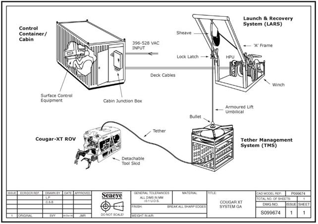
A deepwater ROV system is basically composed of the following sub-systems:
Two sorts of ROV interfaces must be considered:
The surface support vessel can be either:
Dedicated support vessel (e.g. ROV survey activities, subsea interventions)
Drilling rig, DP construction vessel, semi-submersible, etc.
Floating Production System (e.g. FPSO)
The ROV operated systems and the interface impacts on the SPS design and support vessel deck layout have to be defined. This requires to precisely evaluate the subsea tasks to be performed (i.e. the intervention philosophy and the functional requirements must be defined) and the external environmental conditions and limitations.
Industry standard interfaces have been established for ROV intervention, to maximise the potential use of standard equipment and design principles. In general such ROV interface requirements and implementation lay mainly with the ROV Contractors. The purpose of standard ROV interfaces is to re-use intervention tooling in the interests of minimizing life cycle costs and to increase the use of proven interface tooling.
3.2 Subsea structure interfaces
The definition of the interfaces between the ROV and subsea production systems (Document Ref. API Recommended Practice 17H , for more details ??? ) mainly addresses the following topics:
The ROV interfaces are generally located on the SPS equipment in a manner that allows accessibility to the ROV, tools (e.g. manipulator, tool skid) and ROT. This means that the overall dimensions of the ROV and its tooling package (or the ROT) must be taken into account in addition to the required space to manoeuvre, in the design of the SPS. Attention must be paid to the environmental conditions as significant current tremendously complicates the pilot task. This includes visibility close to seabed due to ROV thruster wash.
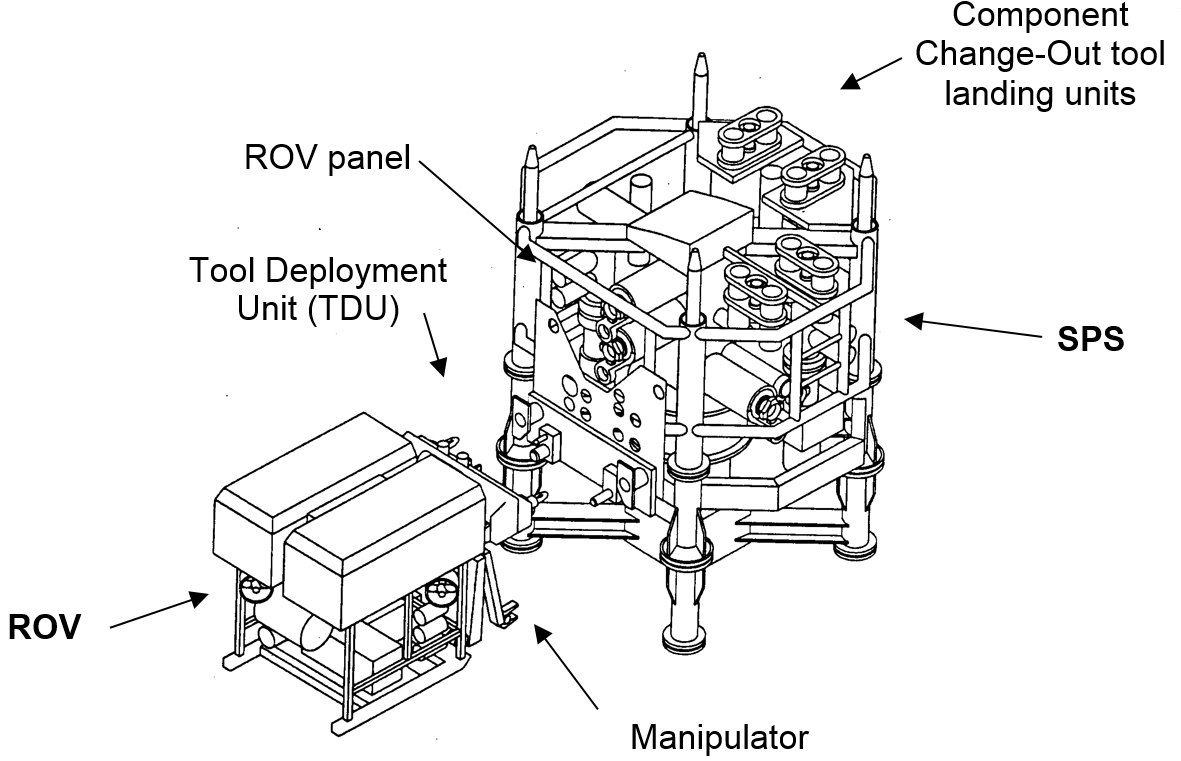
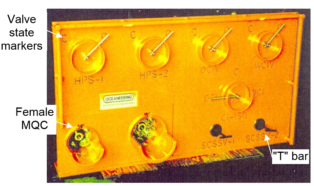
Interface between SPS and ROV are generally performed at the ROV panel. It includes the various interfaces for rotary toque tools and linear pushing tools for valve actuation, provides inboard hubs of MQC or female receptacle for hydraulic intervention tool, etc. (see enclosed Section Chapter 7, ROV tools: "ROV tools"). It also provides docking points (if TDU method is used) or grasping bars for ROV stabilisation (see Section Section 2.2.3, “ROV stabilisation methods” for further details on the stabilisation methods).
SPS may be also equipped with landing units for landing and locking of ROT, e.g. component change-out tool. The functions of these units are to perform the final alignment, to provide soft landing, to lock it during the operation if required and to support tool weight and additional loads.
The SPS and the interface items must be able to support various loads induced by:
An adequate colour and marking system of SPS equipment must be implemented to allow easy identification of:
Structures (for global navigation)
Key subsea equipment (e.g. control pods, latching items)
Inspection area
Intervention interfaces (e.g. ROV panel)
Status of each equipment (e.g. open or close position for valves)
The colours generally used are yellow (most visible colour through a subsea camera), white and orange in combination with black and grey.
Character sizing depends on the distance they should be read, depending on their role (i.e. primary identifier for system location or secondary markers, such as those on ROV panels). They can be from 5cm to 50cm height. Prevention of marine growth and cleaning shall be provided for markers having operational functions for the field life duration.
3.3 With launching and recovery conditions
The interfaces between the surface support vessel (or host facility) and the ROV/AUV system mainly concern (1) the deck layout (i.e. space required by the deck equipment of the ROV/AUV) and (2) the required facilities (e.g. power, communication, etc.) for further mobilisation activities onboard the surface support vessel.
As a minimum, the ROV deck equipment includes:
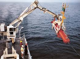
Launching and recovery system (LARS), handling frame or crane, electro-hydraulic umbilical winch complete with drum, cables and umbilical length, capable of operations at the required water depths
ROV control cabin fully equipped (i.e. monitor recorder with hard copy print out off the screen), air conditioned and pressurised as Zone 2, A.60 fire rated
Video display to be located in the support vessel main control room (e.g. DP control, drill cabin)
Direct communication and telephone links between the ROV control cabin and the 'DP' control room
Workshop / maintenance cabin
All required spare parts for above ROV system
As a minimum, the AUV deck equipment includes:

ROV's Subsea Contractor must provide a general arrangement on deck of its equipment/system and the required facilities / connections interfacing with the support vessel.
The surface support vessel must provide a safe working platform for the subsea activities to be performed by ROVs and ROTs. This implies that both support vessel and LARS shall be related for effective operations at the specified environmental conditions or sea state (see Section Section 2.5, “Launching and recovery conditions” Launching and recovery conditions).


