3 Interface Requirement
3.1 Introduction
Typical deepwater subsea field development requires several subsea wells to be drilled at different water depths and locations. These wells will be connected by means of flowline and riser systems to floating production platform positioned near the field.
The main engineering interface for the pipeline design is related to:
For the interface requirement related to SPS and subsea connection, and lay vessel, please refer to the documents:
[3] “Subsea Production Systems” Offshore Reference Book.
[7] “Subsea Connections & Tie-in Methods” Offshore Reference Book.
[6] “Deepwater Installation Vessels” Offshore Reference Book.
3.2 Pipeline End Terminations
A typical subsea pipeline is terminated at both ends with a structure, which has two main purposes: (1) initiation or lay-down head for the actual pipelay operation and (2) for future connection to subsea wells and riser system.
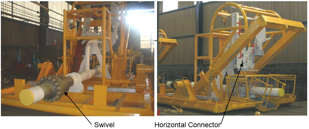
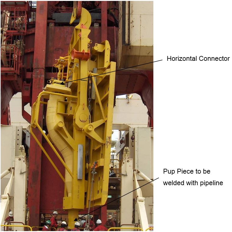
Such end termination structure (Figure 3.1, “In-Line Assembly (Total Dalia Project)” and Figure 3.2, “Pipeline end manifold (PLEM) during installation (Deep Blue vessel, Dalia Project)”) is to be equipped with different pipe fittings such as:
Pipe pig launcher or receiver (to be removed after pipeline pre-commissioning)
Emergency shut down valve, as required after safety case analysis
Horizontal or vertical connection hub, depending on the selected tie-in methods [83].
Pipe swivel (as required) to assure that the PLET will landed within the desired inclination tolerances in order to allow for the direct horizontal or vertical connection.
![[Tip]](tip.png) | Tip Click these links below for access to 3D resources: |
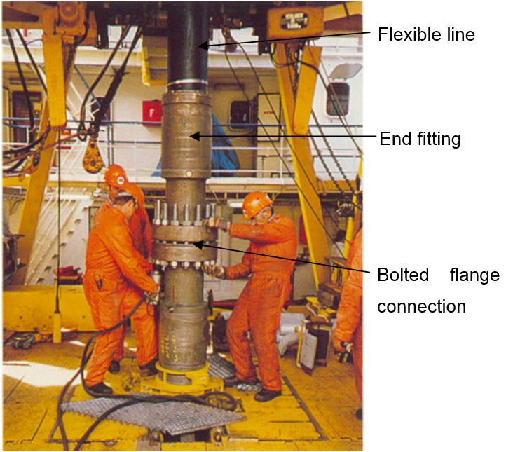
The above section was presenting a connection considering a rigid pipeline section. However, connections can be performed with unbonded flexible lines.
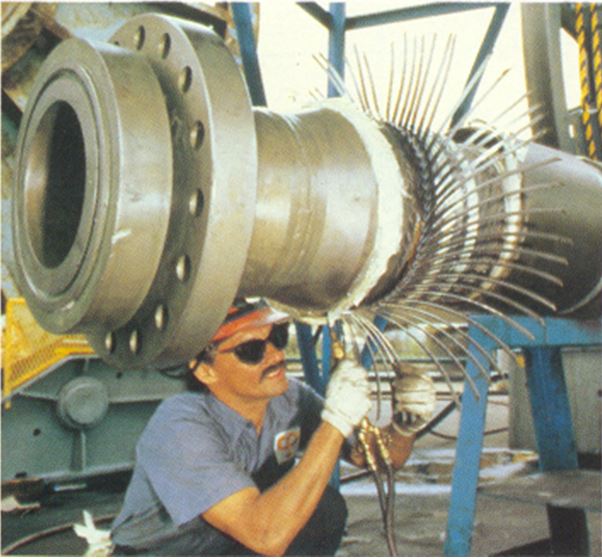
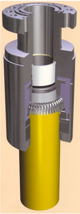
In this case, the flexible pipe structure is terminated with end-fittings at both ends (see Figure 3.3, “Flexible pipe end fitting mounting” , Figure 3.4, “End fitting locking” and Figure 3.5, “Flexible intermediate connection at working platform”). This end-fitting provides a link between the unbonded layers of the flexible pipe structures and the connection at the production platform (as a riser), or SPS or rigid pipe PLET. The end-fitting allows the sealed connection of each layer in one flange assembly .
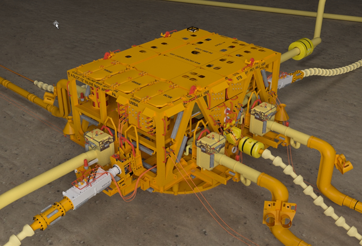
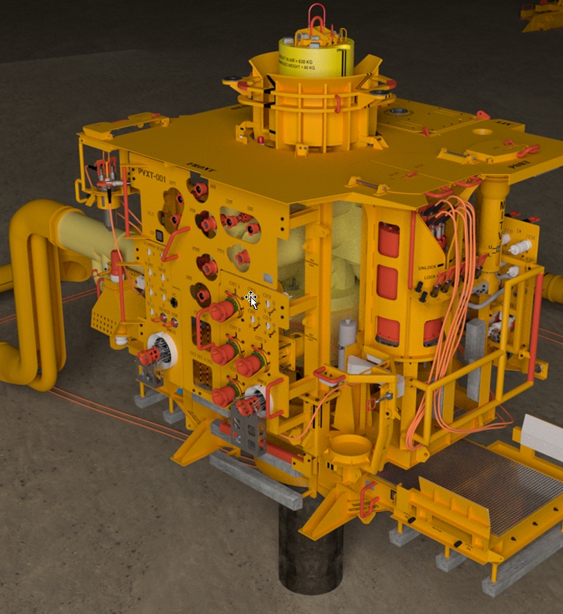
3.3 Subsea Production System
The subsea manifold system or the riser base, where the flowline will be connected to, must be designed and equipped with due consideration of the following additional mechanical aspects (see Figure 3.6, “Deepwater Subsea Manifold” and Figure 3.7, “Subsea Well”):
Space/dimension provision for the selected connector, the tie-in tools and ROV operation envelopes
Permanent and temporary subsea hardware related to the tie-in method
Connection/reaction loads which vary with the tie-in method
Resist to the in-service load conditions such as temperature, pressure, slugging, etc.
Subsea hardwares used for the diverless connection of pipelines and permanently mounted on subsea structure or landed on seabed are typically:
Pull-in sheave and rigging
Landing base for running tools
ROV platform
Alignment modules
Pipeline end termination
Subsea winch
The following are examples of subsea hardware temporarily mounted on subsea structures in order to perform the desired tie-in:
Buoyancy modules
Winch and cables
Protection caps
Blind and test caps
Pull-in/connection tool and pull-in head
Positioning and measuring equipment (subsea metrology for future tie-in spool/er)
Pig launcher / pig receiver
| Tip Click these links below for access to 3D resources: |
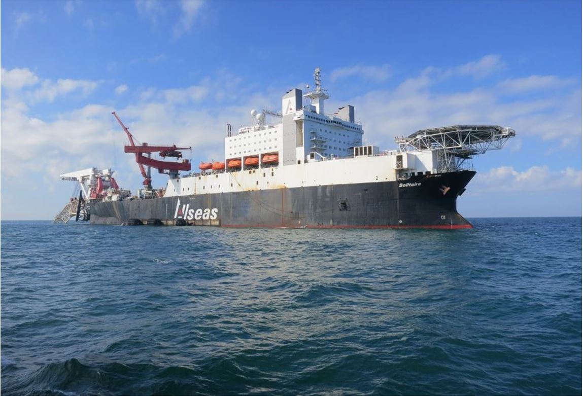
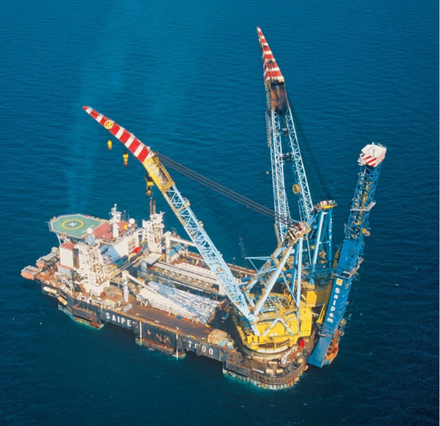
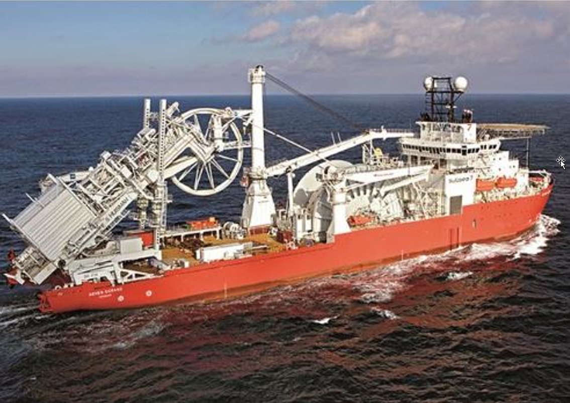
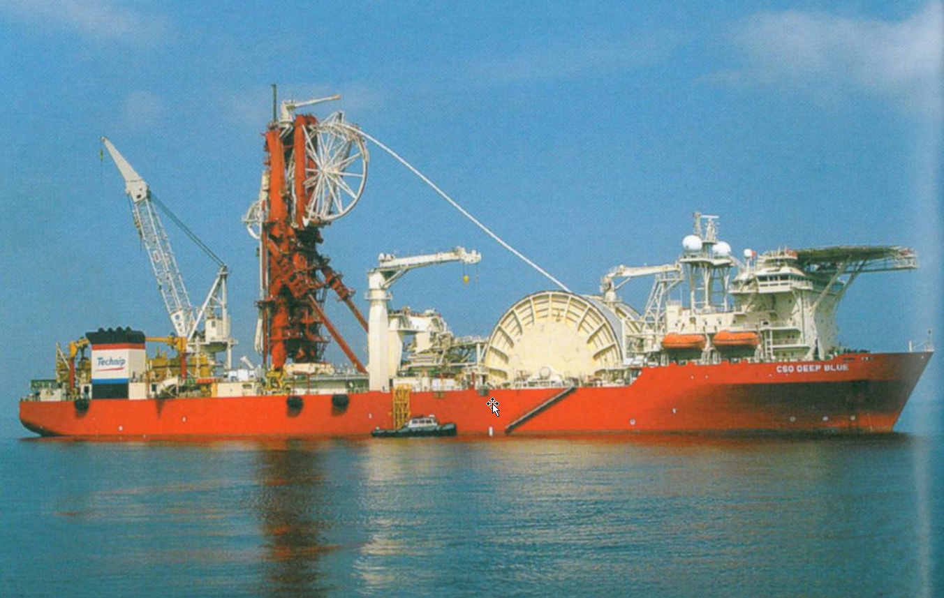
3.4 Installation Vessels
There are three main laying techniques that could be used for installation of rigid pipelines in deep water:
Steep S-Lay
J-Lay
Reel-Lay
Each laying method is further reviewed in document [82] with detailed descriptions of related and latest installation vessels. The deepwater pipelay operations will induce high installation loads onto the pipeline with different cumulative and residual strains which need to be addressed in the pipeline design.
Flexible pipelines and umbilicals are mainly installed using the Flex-Lay methods, which is similar to the Reel-lay method, with tensioners integrated in a laying ramp or a dedicated vertical flexible laying system
The typical dynamically positioned lay vessels are hereafter illustrated: