7 Trenching Techniques
7.1 Introduction
Many submarine pipelines have to be trenched. A trench protects the pipe against damage from fishing gear, reduces hydrodynamic forces from waves and currents, gives a degree of protection from small anchors and from construction vessels’ mooring lines, and may be desirable for safety or environmental reasons. The relative importance of these factors naturally varies from project to project. If the trench is backfilled, protection against fishing gear and wave is fully fulfilled, risk due to others damages is reduced, and heat transfer between pipe and the sea is reduced.
However in deepwater there is no fishing activity no anchor dragging and low hydrodynamic. This explains the fact that most sealines are laid untrenched in current deepwater field development. The requirement for better thermal insulation of the sealines could dictated the sealines to be trenched and backfilled; in transient conditions a trenched sealines could provide a longer shut down time by a factor of 4 when compared to the same untrenched sealine. For the purpose of sealine flow assurance at low seafloor temperature, there is a need to review existing burial or trenching techniques which could be used in deepwater applications.
Jetting was the technique almost always used to trench submarine pipelines. Since jetting techniques were first developed in the 1950s, they have been substantially modified, but their efficiency is much affected by geotechnical conditions of the sea bed. In medium clay, for instance, jetting cuts a neat rectangular trench, but in loose sand it leaves a wide and shallow trench, with side slopes less than 10°, which does little to protect the pipeline. In the wrong conditions, jetting is slow and expensive.
A creative dissatisfaction with the high cost and limited efficiency of jetting led to a search for better trenching methods. There have been two principal axis of development, ploughs and mechanical cutting systems. Each of these systems is appropriate in the right conditions. At first, mechanical cutting systems (bucket wheels, cutter-heads, ripper wheels) were plagued by mechanical and electrical faults, and by sensitivity to bottom soils and topography. These problems have now been largely overcome and good results have been achieved with cutting systems in a number of projects particularly the trenching of power cables in the English Channel.
At the same time, there has been a major development of pipeline trenching ploughs which met a hostile and often derisive response in the past. Ploughing is now an accepted and widely used technique, and in many conditions is the method of choice.
7.2 Plough Technique
Ploughs were used to trench pipelines in the UK and the Middle East in the 1960s. With hindsight, it appears that the difficulty of designing a good plough had been underestimated. A plough designed incorrectly either digs too far and becomes anchored, or fails to penetrate and scrapes along the surface without making a proper trench. Moreover, it is sensitive to soil strength, and cuts at different depths in different soils.
In all subsequent pipeline trenching operations, the long beam configuration has been adopted based on the following considerations:
The plough was to be pulled by a tug with a bollard pull corresponding to plough weight and soil conditions
Accurate depth control was essential, since otherwise the specified trench depth would not be achieved everywhere, and the plough might require more force than the tug could apply.
The outstanding advantage of this configuration is precise and consistent depth control. Skids or wheels hold the front end of the beam at a fixed height above the sea bed. The rear end of the beam carries a share, which cuts the soil and lifts it upwards and sideways (see Figure 7.1, “Figure 7.2.1: Single pass plough (long beam configuration)”).
Mouldboards push the spoil outwards, so that it does not fall back into the trench. Under the share, and fixed to it, there is a rigid heel. In normal operation, the plough runs so that the heel is horizontal, and the plough is in balance under the combined action of the soil force on the front of the share, the reaction under the heel, the pull force at the front end of the beam, and its own weight (usually small by comparison with the other three forces. If the plough attitude alters, so that it cuts less deeply, the heel loses contact with the trench bottom, the heel reaction falls to zero, and the share reaction pushes the share downward so that it cuts more deeply. If, on the other hand, the plough cuts too deeply, the heel itself has to cut the soil, and the heel reaction increase and lifts the share to reduce the cutting depth. In consequence of the long beam configuration, the plough cuts at a uniform depth, and the trench does not change if the soil strength changes (unless it becomes so weak that it cannot support the heel or the skids).
Pipeline can be trenched in different modes:
Pre-trenching mode consists in cutting a trench into which a pipeline would afterwards be pulled/laid
Post-trenching mode involves the pipeline to be laid first, by a lay barge, a reel or a tow, and then the trench is cut beneath the pipe
In both cases it is required that the trench will not collapse, although this is more critical in a pre-trenching mode, where it may take several days before pipeline installation will take place. In a post-trenching it will only be the few minutes the pipeline requires to settle down.
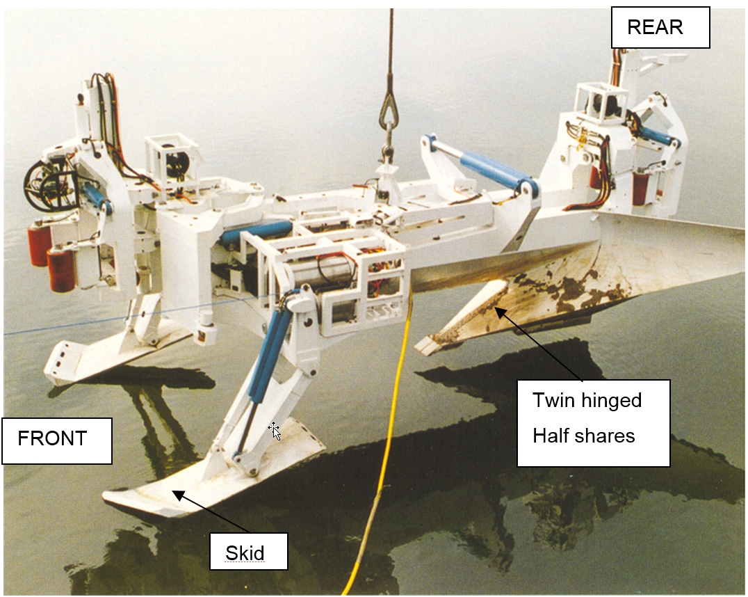
In the post-trenching mode, the principal design problem is to configure the shares so that they can be placed over the pipeline without risk of damage, so that they can close beneath the pipe to excavate a trench under it, and so that the plough can be recovered easily at the end of the operation. The solution to this problem is the ‘’butterfly’’ configuration : twin half-shares are hinged to the rear end of the beam, are placed over the pipe in an open position, and rotate and close under the pipe as the plough is pulled forward (see Figure 7.1, “Figure 7.2.1: Single pass plough (long beam configuration)”).
The dimensions of a plough are primarily determined by the depth and cross-section of the trench it has to cut. The structural weight is determined both by the size of the plough and the draft, the pull force required to advance the plough through the bottom soil. The draft increases rapidly with the depth of trench. In clay, for geometrically similar trenches, the draft increases roughly as the square of the trench depth, while for trenches of constant width the draft increase more than linearly with the depth. In sand, the draft increases still more rapidly with trench depth.
Consequently any plough that cuts a deep trench in a single pass will necessarily be both large and heavy, and will require a large pull force. Once the pull force exceeds 500 tonnes, the difficulties multiply. Not only does the structural weight of the plough begin to become excessive, but friction generated by the weight itself begins to make a significant contribution to the draft. Because the plough is so heavy, it becomes difficult to handle. A large barge is required to transport it, and a large crane to lower it safely onto the pipeline. There has to be a strong link between the plough and whatever is pulling it: even allowing a rather small factor of safety of 2 on minimum breaking load, a wire rope of some 125 mm in diameter is needed to pull 500 tonnes. Finally the pulling system must be anchored, finding good holding ground, and balancing and controlling mooring line tensions become relatively important if the pull force exceeds 500 tonnes, whereas the requirement to anchor against 100 or 200 tonnes is common and easily satisfied, in deepwater lay barge pipelaying for instance.
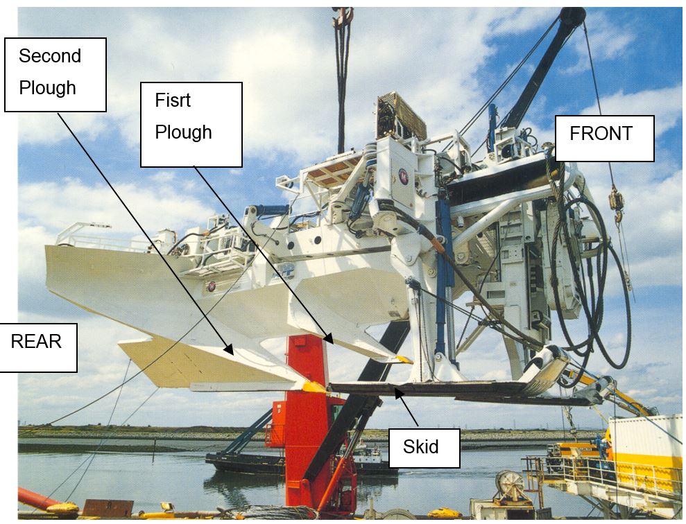
All these factors indicate that a deep trench should not be cut in a single pass, but that it will be better to adopt a multi-pass technique, in which the required depth is reached in two or more cuts. In this concept, the trench is cut by the front plough to a trapezoidal cross-section, with a level bottom and sides at 30° to the horizontal. In the second pass, a deeper triangle is cut from the bottom of the first-pass trench by the rear plough (see Figure 7.2, “Figure 7.2.2: Multi-pass plough”).
The burial performance of the multi-pass plough technique is as follows:
Pipe capacity : 500 mm OD maximum size
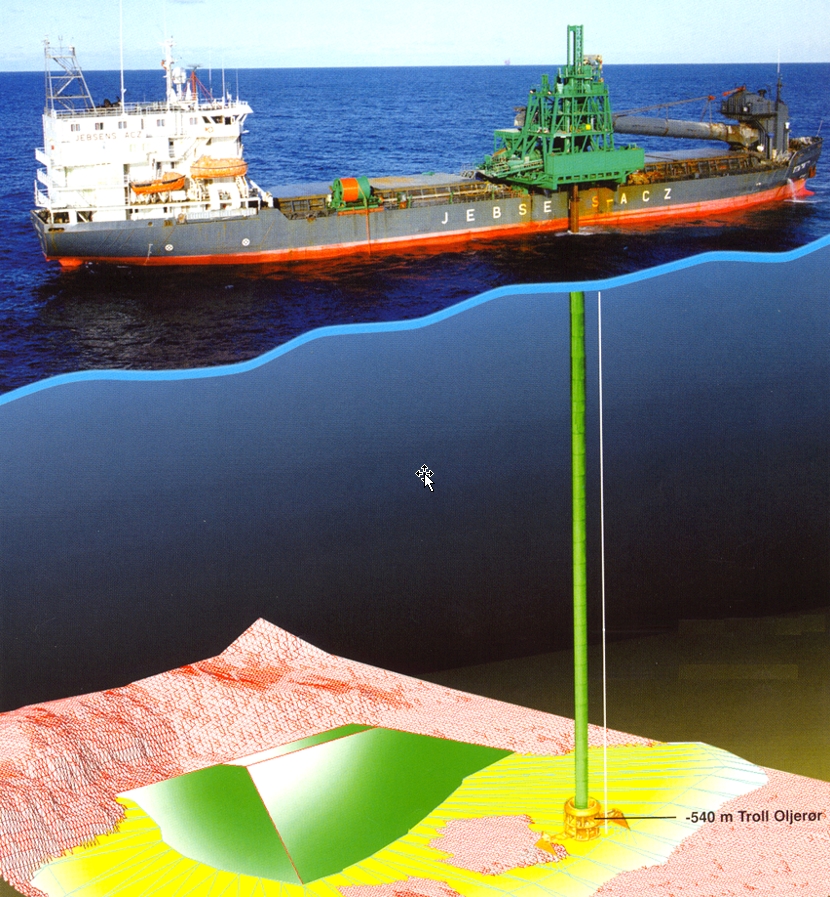
Trench depth : 0 – 1.8 metres maximum
Operational depth : 500 metres maximum
When pipeline engineers speak of ‘’burial’’, they generally mean ‘’trenching’’. Trenching techniques usually leave the pipeline in an open trench. Ploughing leaves the spoil neatly piled along the trench sides, rather than dispersed into the water. As well as eliminating water pollution, this has the advantage that once trenching is complete a backfilling device can move along the trench, to push the spoil back to cover the pipeline. A back filler can be constructed on the long beam principle.
7.3 Jetting Technique
All submarine pipeline burying methods require the preparation of a ditch or trench in which the pipe is lowered during the operation or afterwards. Most methods can be applied successfully in sea beds consisting of cohesive soil such as clays. In cases where the sea bed is noncohesive (e.g. sand) the trench will fill up rapidly, resulting in a too small burial depth of the pipeline.
For those areas where the sea bottom consists mainly of sand and soft clay, the adequate method involves fluidisation of the bottom adjacent to the pipeline over such a length that the pipeline, having lost its support, sags to the desired depth, aided by its flexibility and the load exerted by the fluidisation device resting on the pipeline.
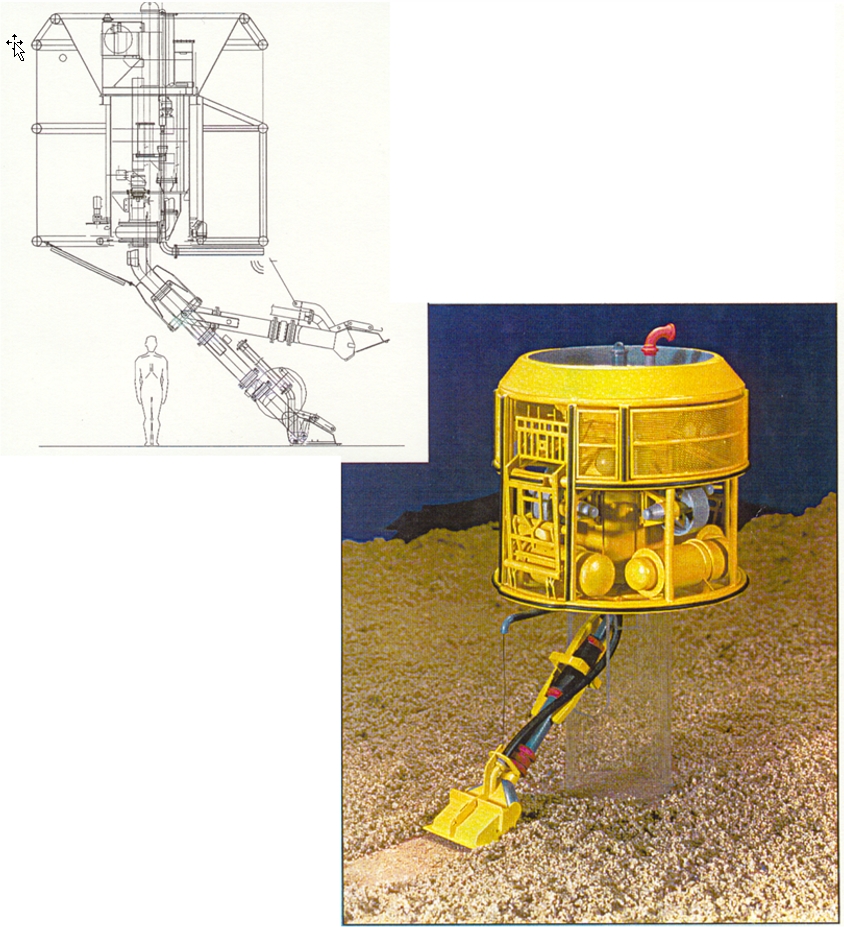
Some pipeline burial vehicles using the jetting technique up to a water depth of 1000m.
The jetting machine is a lightweight pipeline burial vehicle was designed based on the above principle. It consists of a 400 to 1000 HP water jetting system .
The principle of trenching is to create a trench beneath an existing pipeline so that the pipeline will be lowered down into the seabed. The basic steps of trenching are:
Trenching machine will move forward and leaves a trench behind and the weight of the pipeline will cause the pipeline to sag down to the bottom of the trench. Stresses on the pipeline are controlled by adjusting the trench depth created on each pass made by the trenching machine. The allowable trench depth is the function of the pipe properties and also the allowable trenching stresses.
A dedicated pump usually be equipped on each jets and eductors to provide the necessary presurrized water for the trenching operation. The trenching machine will be controlled by an operator for its forward speed, cutter speed, side loads on the pipeline and also the machine direction. The water pressure and flow rates of the jets and the eductors will be adjusted at pump control panel.
The jetting machine can be either slided over the pipeline and pulled by a barge/vessel, or lifted over the pipeline from the barge/vessel
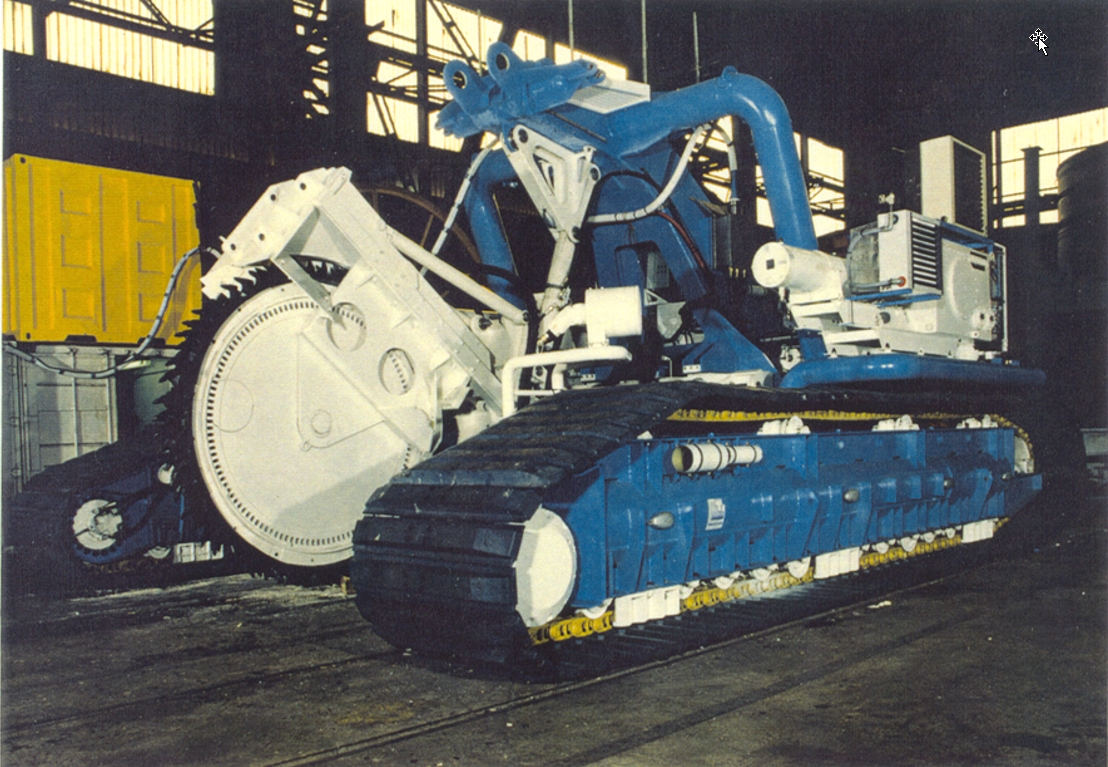
7.4 Mechanical Cutter Technique
For large size pipelines an alternative to a protection technique can consists in an overdesign of the pipe and coating mechanical characteristics in order to make it capable of taking up possible accidental impact loads.
For small size lines, that are power and telecommunication cables, rigid of flexible flowlines or pipelines, flowline bundles, the more convenient protection is to bury them in a properly sized trench; different methods such as sand bagging or backfilling are often more expensive or may prove hazardous for line safety or may not satisfy required protection standards.
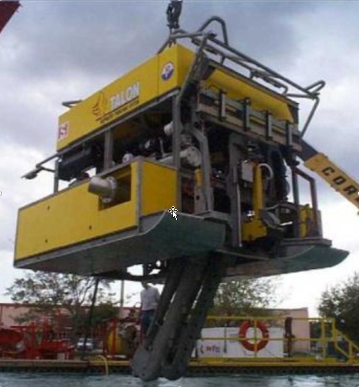
A specific surface controlled trenching system conceived for the task of burial small size lines consists of a steel frame which connects the two motorised tracks and supports the main subsystems.
The vehicle can move on sea bottom by means of large supporting surface hydraulically motorised tracks or flying over the pipeline.
The trenching system consists of a cutting chain which runs on steel rollers supported by a proper frame. The chain is driven through a reduction gear by a hydraulic high speed motor. The chain-frame system is placed at the centre of the vehicle and can rotate in a longitudinal plane in order to reach the selected digging depth; it can moreover rotate laterally to ease the operations of line installation on the supporting rollers.
During operations the line to be buried is held above the trench by means of a roller supporting device which is connected to the digging chain frame. The supporting device geometry and roller design guarantee the acceptable line bending and local loads. In case of flexible line burial a conveying device, consisting of a rigid arm hinged at the vehicle stern, guides, by means of rollers, the line itself onto the trench bottom.
The monitoring of the line supporting device geometry and loading allows a real-time knowledge of the mechanical stresses in the line itself and of the burial depth during trenching.
In general, a trench depth of 2-3m can be achieved with existing mechanical cutter trenching technique.
|
|
7.5 Cutter Suction Dredger
A Cutter Suction Dredger (CSD) is equipped with a rotating cutter head, for cutting and fragmenting hard soils. The soil is sucked up by means of dredge pumps, and discharged through a floating pipeline and pipes on shore, to a deposit area. In some cases, the material is discharged into split hopper barges that are moored alongside the Cutter Suction Dredger. These split hopper barges unload the soil at the deposit area.
A CSD is a stationary dredger, i.e. it does not ‘sail’ when dredging. During dredging the vessel remains on the same location, secured by a spud lowered in the seabed ; by means of winches and anchors, the dredger swings sideways and the cutter head cuts and removes the soil.
The vessel is stabilised with a pile and moves sideways pulling on its sideways anchor lines.
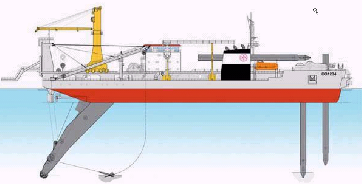
The loose soil is pumped up to the vessel and discharged later or further.
A Cutter Dredger is able to performed its own channel and is able to make a continuous trench up to the onshore cofferdam location where soil has been excavated using a backhoe.
A Cutter Suction Dredgers have been used to perform its own channel, in areas with low tide level. Once the 5.5 m- 6.0 deep channel is made and Cutter sailed away, it is possible to position a shallow water barge inside the channel and reduce the pulling distance. In that case, if the draft of the laying barge allows it, it is possible to position it at close (150 to 300 m) to the cofferdam exit. The pulling distance can, therefore, be reduced.
Moreover, the Cutter Suction Dredger is able to work in hard soil.
The Cutter dredger is mainly used to dig channels and its accuracy is limited : a minimum 20-25 m distance with the adjacent pipeline is required. The trench will be wide, (around 60 m), to allow the access of the Cutter Suction Dredger and the pipelaying vessel. The required pulling force to bring the pipeline string to shore or to the pipelay barge is largely reduced.
7.6 Backfilling / Rock Dumping
7.6.1 Introduction
The requirements of the authorities for a minimum distance (typically 0.9m) between top of pipe and mean seabed level or fully covered pipe have created the need to develop different backfilling methods in addition to the sandbagging:
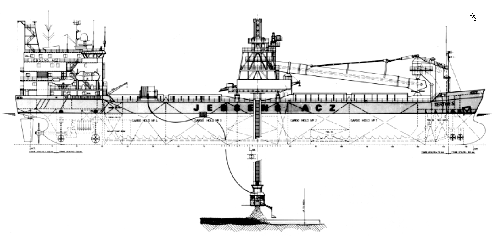
To take the material from the seafloor by suction hopper ship dredgers and pumping it through a floating hose to a DP vessel positioned above the pipeline. The material will then be transferred through a vertical fallpipe down to the gas pipeline.
To use a converted bulk carrier with a DP system. This vessel utilises material taken from shore and placed above the pipeline through a vertical fallpipe equipped with a guiding thruster at the lower end.
7.6.2 System Description
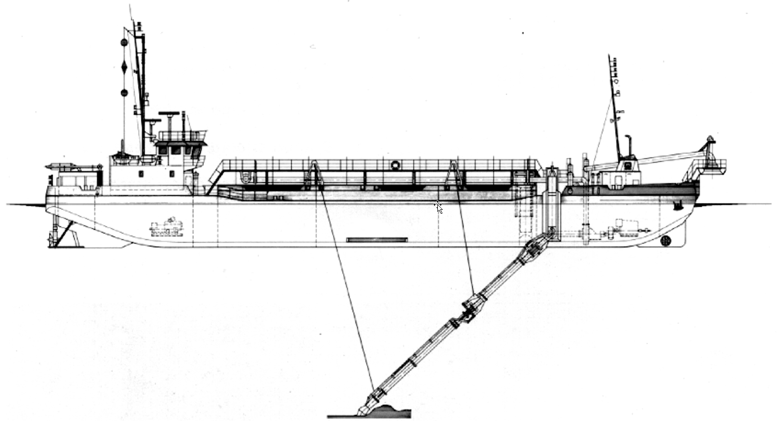
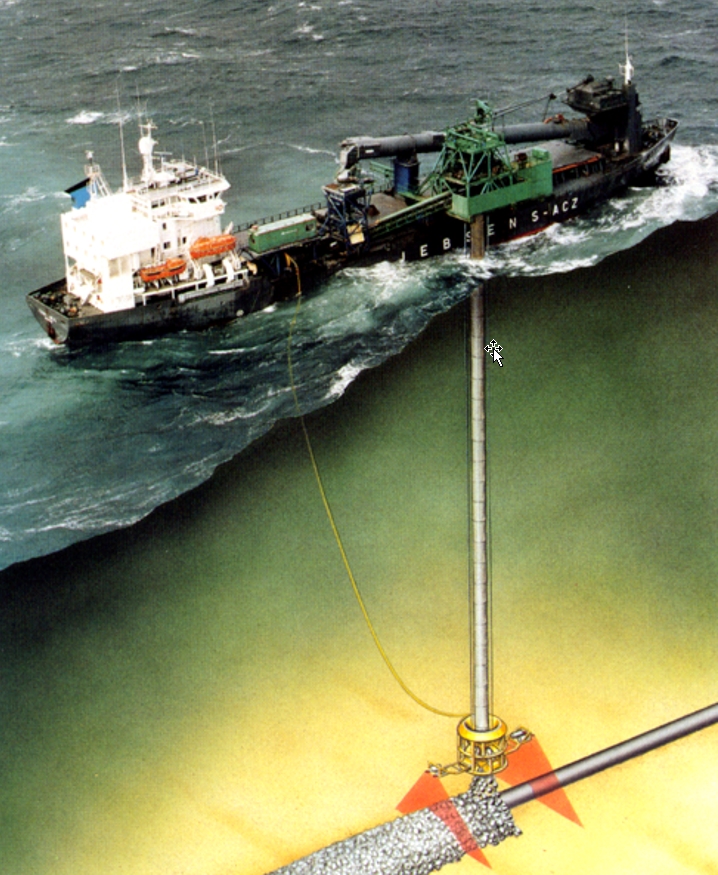
The system based on the use of dredged seafloor material in two layers with fine sand as the first layer and a coarser gravel layer at the top is applicable if these materials are available nearby the pipeline. The spread consists of two trailing suction hopper ship dredgers to dredge the sand and the gravel respectively. A dynamically positioned ship stationed above the pipeline to act as a feeding vessel (see Figure 7.3, “Feeding vessel” and Figure 7.4, “Trailing suction hopper dredger”). The dredgers are linked to the drill ship by a floating hose and pumped the backfill material to the moonpool of the ship where the material was directed to the trench via a fallpipe assembly. The fallpipe string is made up of steel sections and suspended from the derrick hook. It provided guidance to the backfill material from the feeding vessel to the subsea pipeline. A telescopic-joint is incorporated in the fallpipe string to provide flexibility with respect to depth variations along the pipeline.
Navigation of the dump vessel is performed by its DP system. Position references are provided from a combination of bottom acoustic system and surface positioning system. Angle indicators are mounted on the fallpipe giving the distance of the discharge head to the feeding vessel reference point. During unloading of the hopper dredgers, the material is sucked out of the holds using dredging pumps. The water and gravel/sand mixture is pumped through a connection pipe, quick release-coupling and floating hose to the feeding vessel. The dredger takes position towards the feeding vessel in such a way that the 400 m long floating hose is protected as well as possible against the influence of wind, waves and current. For keeping their position, the dredgers used the bow thrusters and twin screw propulsion. For surveying, a sub-bottom profiler is mounted on the lower end of the fallpipe. This made it possible to locate the pipeline during conditions of poor visibility and it was also used as a back-up for the navigation system.
The deepsea dredger as illustrated in Figure 7.5, “Deep sea dredger (R & D)” has been developed for the mechanical backfilling of deepwater pipeline up to 1000m water depth. In this concept, the backfill material (if available) is dredged directly on location nearby the pipeline then directed to the pipeline. Thus, the pumping of backfill material to surface and the discharge through fallpipe are avoided in this efficient and cost effective solution.
The other system is based on a converted bulkcarrier doing the backfilling operation as well as transporting the backfilling material stored in several holds from shore to the location (see Figure 7.6, “Flexible fall pipe vessel in rock dumping operation”). The vessel is equipped with retractable azimuth thrusters for the DP system. The primary navigation equipment for position keeping is interfaced to the DP system and consisted of three different positioning systems. These systems have fixed radio beacons on the platforms in the area or use satellite navigation system DGPS. In addition the equipment could utilise an acoustic underwater navigation system based on transponder located on the seabed. The vessel uses any of these positions keeping systems or a suitable combination. The accuracy of the primary navigation systems enabled the DP equipment to hold the vessel stationary within 2 to 3 meters of a desired position. The system also enabled the vessel to automatically follow a predetermined track at a constant speed varied according to the need. Once the vessel is on location, a fallpipe made of polyethylene is lowered through a moonpool. At the lower end of the fallpipe is an electro-hydraulically driven thruster unit. The thruster unit consisted of three propellers located tangentially to the fallpipe at 120° to each other. This enables the operator to move the thruster and the fallpipe in any direction. The thruster unit is equipped with an underwater navigation system based on acoustic instruments which enables the operator on the vessel to ‘’see’’ the exposed or buried pipeline and the sea bottom profile. This system consists of two sub-bottom profile arrays containing transducers, a scanning profiler with transducers and miscellaneous auxiliary equipment such as TV cameras, lights, etc.
By means of the acoustic reference system the position of the thruster unit could be accurately determined in relation to the vessel or in relation to marker transponders on the bottom. The thruster operator on the vessel could then, by means of the underwater navigation system, position the end of the fallpipe directly above the pipeline and move it in a pattern which ensured correct placement of the backfilled material. In each of the cargo holds there is an excavator mounted on a pedestal. From each hold, there is a belt conveyor which transported the backfill material to a collecting conveyor, taking the backfill material to the hopper above the moonpool from where it is conducted through the fallpipe to the seafloor. In the moonpool hopper, water is added to the backfill material in order to compensate for the displaced water when the backfill material fell through the fallpipe.
7.6.3 Pre-lay Pipeline Support
The installation of pipelines over highly irregular seabed requires a pre-lay gravel support to prevent excessive free-spans and overstressing of the pipelines (see Figure 7.7, “Pre- lay pipeline support”). These gravel supports with heights up to 12 m and sides’ slopes of 1:2 to 1:3 were accurately placed in water depths down to 1000 m. Installation tolerances were +/- 1 m horizontally and +/- 0.15 m in height.